| Author | Message | ||
shane alward New User Username: the_gambler Post Number: 5 Registered: 5-2015 |
has anyone had any experience with brake pumps. I have taken outfeed pipe off brake pump on my SRH8556 shadow and no hydraulic oil flowing. I have ordered a removal tool and will pull pump off next week. not sure if piston is snapped or pump is seized. does anyone know if I will have to remove manifold or not. thanks shane | ||
Robert Noel Reddington Prolific User Username: bob_uk Post Number: 194 Registered: 5-2015 |
The brake pump is screwed into the camshaft cover under the manifold. To inspect the camshaft and pump push rod this cover will need to come off. The carbs are held on with a long centre bolt. The inlet manifold proper is easy to remove not forgetting the water pump by pass. It is possible to remove and refit pumps without taking the manifold proper off. Be careful with distributor cap its next to the rear pump and a slipped spanner could break it. The cover for the cam can be removed complete with pumps. On the underside is 2 bolts for each pump mounting. The pumps can be removed by undoing these bolts. The adjustment shims go between the cover and the pump mounting. Before removing pump. Unscrew the adaptor at top of pump and clean the non return valve inside. Remove lid of reservoir and check the feed filter for obstruction. Check rubber feed hose for obstruction. Refer to workshop manual hydraulic chapter. The pump and reservoir shown in detail. The pumps are simple machines and reliable. There are no seals. The sealing is by very small running clearances that are smaller than a brake fluid molecule. It is ok to LIGHTLY polish bits with BLUNTED 800 grit wet or dry using a bit of spit for lubrication. Polishing should take less than say 2 minutes any longer and its too much. To blunt wet or dry rub it on a bit of steel first. Clean the pump bits with any DOT Brake fluid or methylated spirits. Because Brake fluid strips paint, have a bucket of soapy water and sponge handy. Soapy water instantly neutralises DOT brake fluid. | ||
Randy Roberson Grand Master Username: wascator Post Number: 466 Registered: 5-2009 |
If just the brake pushrod (waisted rod) is snapped, you can get it out using a magnet after you unscrew the pump, if it is not too grunged up: remember you have to get the short broken end as well and be sure to get all the pieces out. If you are not certain remove the intake manifold and take it all apart and be certain. The pump itself can be removed after removing the inlet and output pipes: the outside of the pump is just a sleeve held by two O-rings so pull straight up and it will slip off the pump, it might be tough because the O-rings are hardened due to age; then you unscrew the pump with the special tool. To remove the inlet manifold is not as terrible a job as you might imagine just from looking at it. I did one last year. One of my waisted pushrods was snapped: they often corrode in the thin spot (the waisting) and so fail even though nothing is wrong with anything else. Don't lose bolts and don't drop any into the engine. | ||
Geoff Wootton Grand Master Username: dounraey Post Number: 794 Registered: 5-2012 |
Shane In addition to the above advice, check out Tee-one topics 34 page 490. It can be found here and contains some very useful photos: http://rrtechnical.info/TeeOne/TO34.pdf The parts beneath the valley cover look like this: 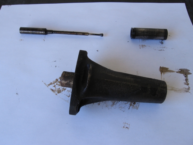 As Randy says, removing the intake manifold is not half as involved as it first appears. Just a case of disconnecting the throttle linkage, stove pipes, engine breather pipe and fuel lines and the whole carburetor assembly lifts off as one, having of course first removed the long bolt. All you then need to do is unbolt the compressor and move it to one side (no need to disconnect the hoses) and remove the intake manifold. About an hours work once you are familiar with the procedure. If you have not already done so, download a copy of Tee-one topics. It is a really valuable source of information. Geoff | ||
shane alward New User Username: the_gambler Post Number: 6 Registered: 5-2015 |
thanks for the info fellas. great stuff | ||
shane alward New User Username: the_gambler Post Number: 8 Registered: 5-2015 |
https://www.youtube.com/watch?v=-Y_7a4tUh_U found this good clip | ||
shane alward New User Username: the_gambler Post Number: 9 Registered: 5-2015 |
hi everyone. I purchased a brake removal tool from flying spares. it appears to be to short some 15mm. it just spins on the union on the top of pump. has anyone else had this problem thanks shane | ||
shane alward New User Username: the_gambler Post Number: 10 Registered: 5-2015 |
update... just got a reply from flying spares and they have had a problem with these and are trying to trace them all. allegedly.....be careful if anyone buys one ask the to measure before they post out. bit of a pain really but I will get over it. | ||
shane alward Experienced User Username: the_gambler Post Number: 11 Registered: 5-2015 |
hi all. can anyone tell me the best gasket sealant to use on the valley cover. thanks shane | ||
Geoff Wootton Grand Master Username: dounraey Post Number: 854 Registered: 5-2012 |
Hi Shane I don't know the range in Australia, so can't answer. The reason I am posting is to check you have read http://rrtechnical.info/TeeOne/to77.pdf. There is much great information here, including the caution about the shorter length bolt on the inlet manifold and how to rotate the engine. A must read for the work you are doing. Geoff | ||
Robert Noel Reddington Grand Master Username: bob_uk Post Number: 313 Registered: 5-2015 |
Silicone gasket gloo use black so it doesn't show. Red hermitite. Chassis grease. Nothing Water (damp) This joint doesn't suffer oil leaks. Observe correct torque for bolts. Also the check that the bolt holes in the crankcase haven't got a high spot around them Ditto the cover. Any high spots file flat using a flat file held flat over the effected area. Also remember that the thickness of this gasket ultimately effects the brake pump push rod setting. ( 0.525 " I believe) My valley cover is unfinished and plain aluminium alloy. Wire brushing makes it look good. Not that much of it is visible when the engine is fully assembled. | ||
shane alward Experienced User Username: the_gambler Post Number: 12 Registered: 5-2015 |
thanks robert and jeff. shorter bolt noted. shane | ||
shane alward Experienced User Username: the_gambler Post Number: 13 Registered: 5-2015 |
Hi guys. in the process of shimming pushrods and waiting for all the gaskets to put it all back together. does anyone know if I should have the accumulators re-done. from what ive read a car that has been sitting around for a period should have them refurbished. thanks shane | ||
Geoff Wootton Grand Master Username: dounraey Post Number: 870 Registered: 5-2012 |
Hi Shane That's a difficult question as it really depends on your vision for your car. If you want to get it back on the road as quickly as possible and do a rolling restoration, then I would wait the few days for the parts to arrive, connect up the system and then evaluate the accumulators. If your intention is to completely renovate your hydraulic system regardless, then why not start straightaway. Your decision also depends on how long it has been since the last recharge. The accumulators should be good for at least 5 years, although in a lot of cases it is much longer than this. Roberts accumulators, I believe, are still ok after nearly 20 years. Geoff | ||
Chris Miller Grand Master Username: cjm51213 Post Number: 364 Registered: 5-2013 |
Hi Shane, If your accumulator is at specified pressure, you don't need to do anything with it. If it ain't broke, don't fix it. There is a way to measure the pressure in the accumulator, but it is not straight forward, and relies on a few assumptions, most notably that your ACV is calibrated at 2,500 PSI, and most are more like 2,300. However the following calculations can be adjusted for the ACV threshold. Unfortunately, knowing the ACV cut-out pressure is just about as difficult as knowing your accumulator pressure. Regardless... Empty the accumulator with the brake pedal cycle procedure. Mark the level of brake fluid on the sight glass. Run the engine and watch the level slowly drop until it stops and continue watching until you're really sure it has reached it's minimum level. Measure the drop in level. For System 1 (forward of the two) it should be about an inch. Multiply the level drop by the area of the reservoir, which for System 1 is about 20 sq.in. to get the volume of brake fluid used. Call it "B". The pressure in your accumulator is: 2,500 ( 32-B ) ----------------- = Nitrogen PSI 32 Obviously, you'll want to confirm my rough approximation for the area of the brake fluid reservoir for System 1 (20 sq.in.) and you'll want to actually measure the area of the brake fluid reservoir for System 2. You'll need to make careful measurement of the level drop and this is tricky, because it can fool you. This is approximate, but you can do it on your driveway, in your suit, with a beer in your hand, in about five minutes. I have filled my reservoir precisely so that the fully charged accumulators will drop fluid level to the "Min" mark on the sight glass, so I can tell quite easily if my accumulator are properly charging. When I notice that I am not hitting that "Min" mark, then I need to investigate because something is wrong. Chris. | ||
Brian Vogel Grand Master Username: guyslp Post Number: 1548 Registered: 6-2009 |
I am going to speak what some people will declare as heresy with regard to accumulators. In Shane's case I will almost guarantee that they are, at best, partially to almost fully depleted of charge just based on his prior descriptions of the car's state. Based on the accumulators I've opened so far, particularly if they've been overhauled with the diaphragms that have the really heavy "rubber bubble" at the center, it is highly unlikely that they will have ruptured (though not impossible). On SY1 cars it is absolutely possible to recharge the accumulators in situ and I believe this is discussed in at least one issue of Tee-One Topics. Take a look through the Tee-One Topics Master Index and then the appropriate issues in the RROC-Australia Tee-One Topics Archive. It is very easy to put together a "home charging station" for accumulators for those who don't want a lifetime supply and massive bottle of nitrogen and regulators, etc. Take a look at this article on building a home recharge kit for SY accumulators. Brian | ||
Jim Walters Experienced User Username: jim_walters Post Number: 36 Registered: 1-2014 |
Shane, need some history to be able to advise on rebuilding the accumulators and valves. Had the car been sitting unused for a couple of years or more? Have you removed the top of the fluid reservoir and cleaned it out recently? Has the brake fluid been changed in the last two years and the system flushed with new fluid? When was the last time you did a brake pedal pump down test and what were the results? The answers to these questions will determine whether you should have them rebuilt or not. SRE22493 NAC-05370 www.bristolmotors.com | ||
David Gore Moderator Username: david_gore Post Number: 1702 Registered: 4-2003 |
As far as I am concerned, the answer is simple and based on the importance of preventative maintenance in minimising unexpected and embarrassing failure to proceed; overhaul the accumulators. | ||
shane alward Experienced User Username: the_gambler Post Number: 15 Registered: 5-2015 |
I have decided to get them overhauled. ive replaced the pushrods, updated pushrod housing to the newer style. also have new thermostat,radiator hoses and brake pumps on order...thanks for the advice .shane | ||
Robert Noel Reddington Grand Master Username: bob_uk Post Number: 335 Registered: 5-2015 |
The purchase of properly overhauled spheres maybe pricey. But mine have lasted so far 19 years. 90 pumps both systems. plus I have the option of a quick recharge when they do start to get low. I think the spheres will out last me. Recharge at 30 pumps. Overhaul of the pumps and ACVs is all within the scope of diy. Master cylinder if fitted is best replaced with new if faulty. Spheres are best sorted out with replacements rather than diy overhaul because of the amount of tooling to be made or acquired. The cost of which will probably exceed the cost of the replacement spheres. If the replacements last 20 years as mine have (still good) then the tooling will be redundant. Then as others have experienced on this forum the process of diying spheres is not as easy as it seems. It's not the sort of job that one does not want to do multiple times. Cross threading something is always a danger. The spheres also buffer the pulses from the pump. Without or low nitrogen means the pulses are not buffered or soaked up by the gas springiness. My spheres cost 140 quid for two. In 5 years time todays price will seem cheap. | ||
Vladimir Ivanovich Kirillov Prolific User Username: soviet Post Number: 288 Registered: 2-2013 |
The Camargue's brake pumps are lying in a sealed tin of clean petrol. Its an experiment to see if they can be taken apart as they are certainly seized. This is an effort to resurrect the dead. I don't give it much hope. Will let you know around Xmas when I return to my batcave if this was successful. I am expecting corrosion, loss of metal and other indications to declare they are indeed the dead, deceased parrot | ||
shane alward Experienced User Username: the_gambler Post Number: 26 Registered: 5-2015 |
hi fellas. im having trouble removing nitrogen sphere from the valve body... I took the whole unit out valve body with spheres connected. just wondering how much pressure should be applied. I am using an oil filter removing belt. they seem to be ultra tight anyone have any tips | ||
Geoff Wootton Grand Master Username: dounraey Post Number: 912 Registered: 5-2012 |
Hi Shane Hold the sphere in your one hand and use a hammer to tap off the acv. A few sharp taps in the correct direction should free it. Geoff. | ||
shane alward Experienced User Username: the_gambler Post Number: 27 Registered: 5-2015 |
thanks Geoff | ||
Brian Vogel Grand Master Username: guyslp Post Number: 1599 Registered: 6-2009 |
Shane, Geoff has given you the best advice. Typically a firm (not outrageously hard, but not delicate) rap or two on the ACV body will knock it loose from the sphere. These things are not supposed to be tightened such that they'll stay attached forever, but some have been overtorqued and others have simply "semi-fused" since they've been together for years and anti-seize wasn't used when putting them together. When mating or removing the accumulator from the ACV when the two are off the car I've always used a hammer. When you're putting the ACV back on simply hand tighten then give a single firm tap with a hammer to snug it up. If you want to be precise you can clamp the ACV upside down in a vice and use a torque wrench on the hex fitting on the bottom of the sphere to tighten it to the ACV. The sphere to ACV torque tightening figure is 55-60 ft-lbs, which is not all that much more than the 45-50 ft-lbs you're supposed to use for the road wheel nuts (AKA lug nuts). Brian | ||
Robert Noel Reddington Grand Master Username: bob_uk Post Number: 429 Registered: 5-2015 |
Where the sphere joins the ACV using a BLUNT rounded end cold chisel hit the sphere not the ACV at the join. Hit it square on, not trying to turn the sphere just a shock to the threads. Recommend by Citro�n guys. Chain wrench on the clamping ring that holds the sphere together. Pencil mark the clamp ring and sphere any movement STOP. This ring is fecking tight and they don't move. Its in the workshop manual. Once the sphere has moved it should spin off like a oil filter. When refitting the ACV to the car leave the pipe fittings and the mounting bolts loose until every thread is started. Don't forget the wire clips for the wires to the pressure switches. | ||
shane alward Experienced User Username: the_gambler Post Number: 28 Registered: 5-2015 |
hi fellas. I've tried all methods above and they wont budge. I will have another try tomorrow... | ||
Chris Miller Grand Master Username: cjm51213 Post Number: 380 Registered: 5-2013 |
Hi Shane, The first time I did this, I bolted the ACV to a 2x4 using the mounting holes. I held the sphere with a vise. It felt like it took a lot of torque, and I was fearful that I was about to break something, but it did come off. On later projects, I held the sphere with the wrench that I use to disassemble it. You're gonna need one of them, too. Brian and Geoff will probably show you their designs. Here's mine: http://au.rrforums.net/forum/messages/17001/15472.html?1400031277 and here is the version I built for a particularly difficult sphere... http://au.rrforums.net/forum/messages/17001/16236.html?1409428464 | ||
Brian Vogel Grand Master Username: guyslp Post Number: 1600 Registered: 6-2009 |
Shane, My guess is that you're going to have to be "more persuasive." Get a heavier hammer and whack the flat on the ACV harder. I have never known of one that didn't suddenly break free and behave in just the way Bob describes: screws right off. When you put this back together use a tiny bit of anti-seize on the threads so you (or the next custodian) won't have to go through this the next time. If you think this part is tough I hope you don't have recalcitrant spheres. Mine required the addition of another long piece of pipe to slide over the end of the 32" handle on the pin wrench and several strong whacks with a 3-lb hammer to finally break the ring free. I also used anti-seize when I put the accumulator itself back together. Here's the accumulator pin wrench I had made: 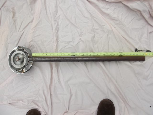 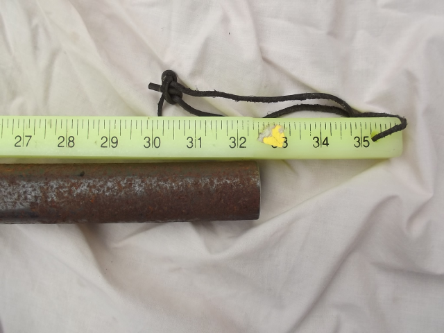  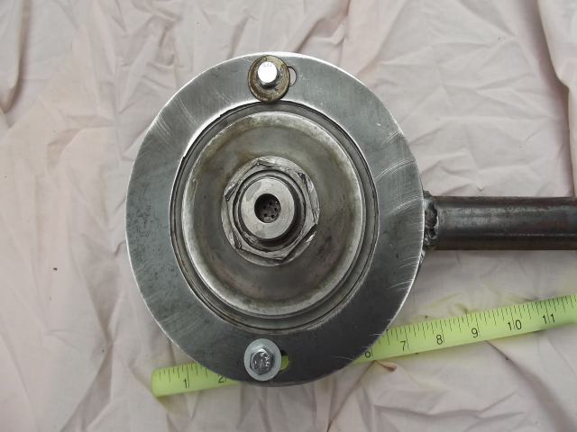 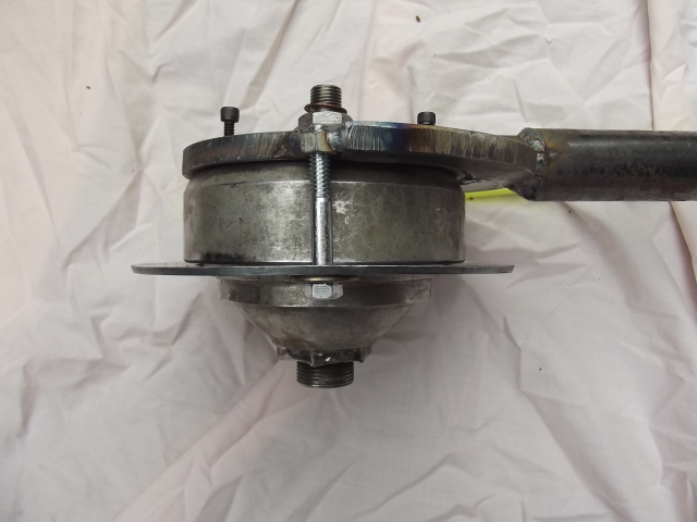 And here's the setup I used to hold he accumulator ends in a vice: 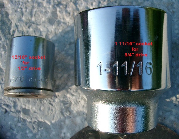 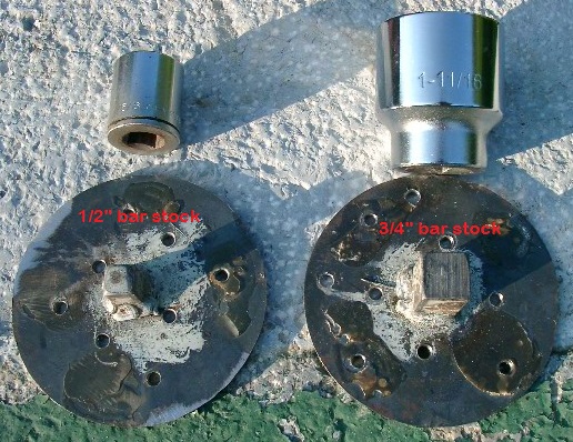 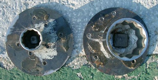 And, finally, the two in action together: 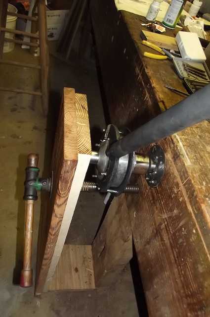 The only thing I'd do differently is that I'd drill far fewer holes in the plates for the holder and use significantly sturdier screws to hold them in place. I hadn't realized just how much force I was ultimately going to have to apply and used screws that just couldn't hold up under the strain except in quantity. Brian | ||
Kelly Opfar Experienced User Username: kelly_opfar Post Number: 41 Registered: 7-2004 |
Here is a pic of the wrench I made just for removing the sphere from the ACV: 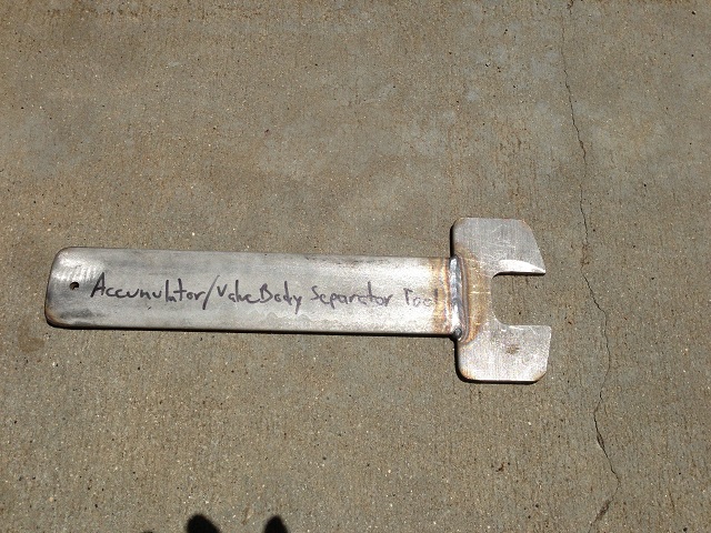 I held the ACV with a vise and the wrench fits on the hex on the sphere. | ||
shane alward Experienced User Username: the_gambler Post Number: 29 Registered: 5-2015 |
thanks for all the help gents. all done now just needed to use a larger hammer and give it a good whack. I had trouble finding a large allen key or large hex for undoing ACV to replace the o rings. I welded a nut onto a bolt that fits into ACV saved me spending $40 for an allen key that i may only use once. s | ||
Brian Vogel Grand Master Username: guyslp Post Number: 1605 Registered: 6-2009 |
Just for the historical record, a scrap piece of 1" hex bar stock (ask at your local machine shop or metal shop) is the perfect thing for undoing the end plug on the ACV. I just used that along with the 1" socket and breaker bar with the ACV in a vise. The breaker bar was probably overkill but it freed up immediately. Brian | ||
Brian Vogel Grand Master Username: guyslp Post Number: 1606 Registered: 6-2009 |
I should have included this photo with that last post since I did include the hex bar stock in the photo: 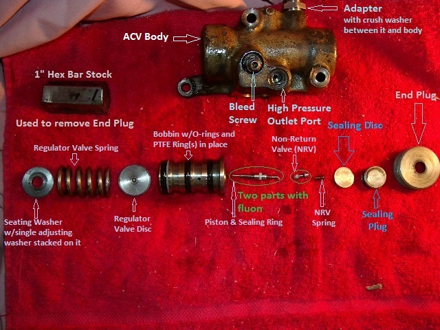 Brian | ||
Geoff Wootton Grand Master Username: dounraey Post Number: 917 Registered: 5-2012 |
Another alternative is a coupling nut from your local hardware store. http://www.homedepot.com/p/Everbilt-3-8-in-16-tpi-Zinc-Rod-Coupling-Nuts-822281/204337391 Note this is just a quick example - they do sell the correct size - I bought and used one. Geoff | ||
Brian Vogel Grand Master Username: guyslp Post Number: 1608 Registered: 6-2009 |
Geoff, Interesting. I wouldn't have thought that 1" coupling nuts would have been an "on the shelf" item at Home Depot/Lowes/etc. One in that size would certainly be more than substantial enough to work just fine for the intended purpose. It doesn't require Herculean effort to get that end plug undone (and should not have Herculean effort applied when putting it back in - Check Chapter P for the specified torque tightening figure). Brian | ||
Geoff Wootton Grand Master Username: dounraey Post Number: 918 Registered: 5-2012 |
Brian You are absolutely right. I typed before putting my brain into gear, or should I say, memory. In fact I bought the coupling nut from a local fastener company with a trade counter. It cost $5, which was their minimum charge. I do recall seeing the nuts at home-depot, but from their website, they only go up to 3/4". This is probably where my false memory came from. I guess ultimately it is a case of finding whichever supplier is nearest to you - machine shop for hex rod or fastener supplier for coupling nut. Shane's solution is a good one, but I'll guess most of us don't own welding equipment. Geoff | ||
Chris Miller Grand Master Username: cjm51213 Post Number: 381 Registered: 5-2013 |
I used Shane's solution, without the welding; I used just the nut and a socket. It was a little low profile, but it worked pretty well. | ||
shane alward Experienced User Username: the_gambler Post Number: 30 Registered: 5-2015 |
some of the work done so far .new fuel pump. points. plugs rotor button. dizzy cap. leads. thermostat. radiator hoses. fan belts. brake pumps. brake push rods and housing. acv kit. accumulators replaced. flexible brakes lines. steel brake lines. fuel filler hose. spin on oil filter.. would it be wise take brake master cylinder out to overhaul and change diff and transmission oil? not quite broke yet but spent some serous $$$ cant wait till I actually drive her | ||
Jeff Young Prolific User Username: jeyjey Post Number: 223 Registered: 10-2010 |
I�d at least check the levels in the diff (and the two trunnions, one on each side of it). Replacing the oil wouldn�t hurt, but old oil isn�t nearly as bad as no oil. Also, did you grease all the u-joints (back axle, drive shaft, steering)? And a few drops of light oil on the dizzy shaft? I�ve a T2, so I know nothing of the master cylinder. Cheers, Jeff. | ||
Brian Vogel Grand Master Username: guyslp Post Number: 1609 Registered: 6-2009 |
Shane, Jeff is correct. Just be be certain that you are able to remove the fill plug on the back of the final drive/differential case before you try to remove the drain plug on the bottom. There are horror stories of a sad few who drained it first then found that it was sheer hell to get the fill plug off. Also get yourself a bunch of aluminum crush washers. They were available at a very good price several years ago from autohausaz.com. I ordered fifty 007603-027101 27mm Aluminum Seal Washer; 27x32x2mm, for less than two cost through Crewe Original sources and these work perfectly well. If you know anyone who colors their hair have them keep the applicator bottles for you. These things are the best tool I've ever found for refilling the EP oil in the trunnion/Detroit joints. Brian | ||
Geoff Wootton Grand Master Username: dounraey Post Number: 920 Registered: 5-2012 |
Hi Shane I would change the diff oil. It's a quick win - easy and cheap to do. Also oil inside the rubber boots. I'd check out the master cylinder before replacing it. I found the best way to bleed it is with a hand operated vacuum pump. Transmission oil - If in any doubt, I'd change it. I know it's a hassle, but given all the good work you've done so far it would be a shame to risk the autobox if the fluid has never been changed. I'm told you can get a good indication from the color and smell of the fluid on the dipstick. May be worth looking this up. One thing I would advise you to do is keep a log of all the work you have done so far. It's really useful a year or two down the line. Geoff | ||
Brian Vogel Grand Master Username: guyslp Post Number: 1610 Registered: 6-2009 |
Shane, Geoff also gives excellent advice regarding the maintenance log. If I did not keep a log I know I'd forget "what I did when." I use an MS-Access database that's available as a free template. See the thread MS-Access Electronic Maintenance Log. I'm an "agnostic" as far as belief in changing transmission fluid. As long as it's reddish, clear, and does not smell burnt you're good to go. I'm currently driving a truck with a hair under 270K miles and a car with 196K miles on them that have never had their transmission fluid changed. I've never changed transmission fluid as a routine maintenance item on any car I've owned, including the RRs because my personal experience suggests it's not necessary unless something has already gone wrong. My father, who was a safety supervisor and fleet manager for the USPS regional office never did, either, and most of his automotive maintenance practices were strongly influenced by what had been found necessary, or unnecessary, in fleet maintenance. Brian | ||
shane alward Experienced User Username: the_gambler Post Number: 31 Registered: 5-2015 |
thanks for the advice fellas | ||
Robert Noel Reddington Grand Master Username: bob_uk Post Number: 444 Registered: 5-2015 |
How to check master cylinders before fitting to car. Put master in a vice don't crush it. Fit a 3/8 unf bleed screw to the out let port. Fill the inlet port with brake fluid which must run out of the output port. Close bleed nipple. The master should hydraulically lock up and the push rod barely move. Leave bleed screw closed fit to car. Fit inlet pipe. Open bleed nipple in master and allow the fluid to run. Shut nipple and the master should again hydraulically lock. Remove bleed nipple and then fit output pipe. Then bleed from rear calipers. When fitting the output pipe if the brake pedal is held down then the fluid from the reservoir cannot flow because the piston is blocking the inlet port inside the master. This stops fluid running while the output pipe is screwed in. Push rod adjustment. Adjust the push rod until the brakes won't release. Back off until the rear brakes release plus half a turn. Road test car. If the rear brakes start to drag as the car warms up which this system is prone to do. Stop immediately and back off another half turn. Pick a dry day so you can drive the car with rat trap cover off. Note that if the master won't bleed then the adjustment may be to tight and obstructing the inlet port inside the master because the piston can't fully return to open the port. A good sign is that when the caliper nipple is opened fluid dribbles out on its own accord due to gravity. Its worth letting this run for a few minutes because often gravity does the bleeding for you. Recently I put a wheel cylinder on a Ford Escort and gravity bleed it and the pedal was up the top and solid. So I gave it a quick pump squirt and the jobs a good un. Also note that when the pedal is off the calipers are connected to the reservoir by the return line from the brake valves in the rat trap. So if a caliper nipple is opened on the power brakes then fluid will flow due to gravity. This will bleed the power brakes down stream of the brake valves. Also if the caliper pistons are fully retracted then moved out and fully retracted any air will be pushed back up the line and into the reservoir. Doing this a few times will bleed both the power brakes and the master cylinder brakes. On some all makes cars the front calipers tend to drag. A solution is to allow a SMALL about of end float in the wheel brg. This causes the disc to move side ways by a TINY amount which clears the pad away from the disc a WEE bit. Easy peasy lemon squeasy. I have not worked out a way of bleeding from the comfort of the drivers seat but I am working on it.  | ||
Geoff Wootton Grand Master Username: dounraey Post Number: 924 Registered: 5-2012 |
Shane Regards your master cylinder, these are notoriously difficult to bleed, which may give the impression they are faulty. The problem is the master cylinder comes (reputedly) from a Morris Minor. As such, it is a poor match for the large caliper. It only shifts a small amount of fluid, so you tend to end up chasing air pockets around the cylinder in the caliper when trying to bleed the system. The answer is to jack the rear of the car up as high as possible so the air "floats to the top" during the bleeding process. A much better solution is to use a vacuum pump to suck the fluid through. I use a hand operated one that cost around 40 bucks. There is an excellent article on this subject in Tee-one topics, volume 47, page 697. Geoff | ||
Robert Noel Reddington Grand Master Username: bob_uk Post Number: 448 Registered: 5-2015 |
The master cylinder on a Morris Minor is fitted inside the chassis rail and is made from cast iron and is filled directly by a cap under the carpet. The Shadow master is not a Minor one. The problem with bleeding is well known the feed pipe from the reservior to the master is quite long and only slightly bigger than the 3/16 brake lines. This doesn't help with flow. Vacuum bleeding is fine, If after 3 mins there are still bubbles then the master seals are maybe allowing air in due to too higher vacuum pulling pulling the seals away from the bore. So lower vacuum. The difference in height between the reservior and the master gives head or hydrostatic pressure which keeps the master seals against the master cylinder bore wall. | ||
shane alward Experienced User Username: the_gambler Post Number: 33 Registered: 5-2015 |
Hi guys. just an update. I have installed the brake pumps put manifold and carbs back on. done the accumulators new radiator hoses fan belts and such. I have now found the water pump housing has a leak were it is corroded so next job is to take that off hopefully don't find to many surprises. taking a long time to get things done as I work 6 days a week but I will get there | ||
Jeff Young Prolific User Username: jeyjey Post Number: 229 Registered: 10-2010 |
Hi Shane, I would recommend a new aftermarket water pump. It's barely more than the rebuild kit, and they seem good quality. I'm normally fairly allergic to aftermarket parts (having been burned countless times with Land Rover parts), but my genuine rebuild kit seals failed after less than 2 years, and the aftermarket pump I then installed is still going strong. Cheers, Jeff. | ||
Jim Walters Experienced User Username: jim_walters Post Number: 43 Registered: 1-2014 |
Shane, if you buy a new aftermarket water pump I am interested in obtaining your old one. I'm looking for cores for these as well as accumulator valves so I can rebuild them and have them ready to go on the shelf on exchange. Will gladly pay shipping. Thanks, Jim. SRE22493 NAC-05370 www.bristolmotors.com | ||
Robert Noel Reddington Grand Master Username: bob_uk Post Number: 518 Registered: 5-2015 |
Unusual water pump leak caused by corrosion. I saw a pump from a Rover P4 90. 2635cc engine. The aluminium casting had a hole in it and when poked around got much bigger and the coolant drained out fast. Photos please of the corrosion. Don't worry how long it takes just plod through everything making good as you go. The jobs finished when the jobs finished | ||
shane alward Experienced User Username: the_gambler Post Number: 34 Registered: 5-2015 |
no worries jim I will let you know. Robert its not the water pump that is leaking its the housing that appears to be corroded . I will certainly post some photos wont be taking it out till next Friday.. | ||
shane alward Experienced User Username: the_gambler Post Number: 35 Registered: 5-2015 |
update. finally got to drive my car today. finished bleeding brakes and drove out of my steep driveway without ending up in neighbours lounge room. really happy thanks for all the help on this site. now just need to buy new tyres and try and obtain a blueslip for registration. any of you fine gentlemen know were I can purchase some white wall tyres in the Newcastle area | ||
David Gore Moderator Username: david_gore Post Number: 1936 Registered: 4-2003 |
Shane, see if the following supplier in Newcastle is still in business, they claim to have outlets in the USA and in Newcastle NSW: http://www.classic-usa-cars.com/ Otherwise try the local Hunter region car clubs catering to American classic cars as their members would be fitting white wall tyres to their vehicles. | ||
Robert Noel Reddington Grand Master Username: bob_uk Post Number: 882 Registered: 5-2015 |
Two types of white wall the wide band and narrow band. The Shadow ones are narrow band. In the UK theses are widely available for a little extra money. To keep mine looking good I wipe with white spirit and sometimes carefully paint with white enamel undercoat thinned down with white spirit. Other colours are available. Red looks good. Esp with dark coloured cars. Not all cars had white walls some had just plain black. My boss bought a new T2 and it had plain tyres because he thought the white walls were vulgar. |