| Author | Message | ||
John Rowney Experienced User Username: johnrowney Post Number: 69 Registered: 02-2015 |
I am after any help and advice that Forum members can give regarding the driving mechanism for my Wraith WXA68�s blind in the division. WXA68 is a 1938 model by HJ Mulliner with division and high vision. I had reconnected the cord system a couple of times over the years, but it usually came off the system after a few uses, probably due to misalignment of the cord. I have still got the engine out (being rebuilt by Garth Selig in Sydney), but I have been trying to fix a few miscellaneous things in the interim. Hence my trials today to really get a handle on the blind and fix it properly. I have the electrics on the car completely disconnected while the engine is out, so that I rigged up a battery to drive the mechanism. The chain drive is in the photo below. I went through everything and found out how all the cord really works. I reconnected the cord, and drove the chain around getting the blind to work reasonably well. I then busted the ageing cord. I got a new one, and rigged it up, but after a couple of cycles I broke the new cord! I then looked more carefully at the driving mechanism. In the photo, on the left upper part of the chain is the wheel where the cord is looped. There is a switch relay mechanism on the Left hand of the drive chain mechanism, but this does not electrically switch when activated. Obviously it is broken internally. Normally it should activate when the trigger on the chain ( on the right lower section of the chain) hits it. I was able to drive the motor and the chain using my external supply, but I sense that the switch serves some real purpose. There is an electrical connecting block with several interconnections which I don�t understand (rather hidden where four wires come out from under the timber in the top left of the photo). Does anyone know anything about this rather simple mechanism? Unfortunately my even simpler mind can�t really fathom out why I have broken two cords, but I suspect that it is because the electrical system should really give better control. The switch obviously must serve a purpose, but it does not function as it should. Any clues you might have would be most welcome. I imagine that division blinds on HJ Mulliner Wraiths and PIIIs may be quite rare and that there may be very few records of how this system works. 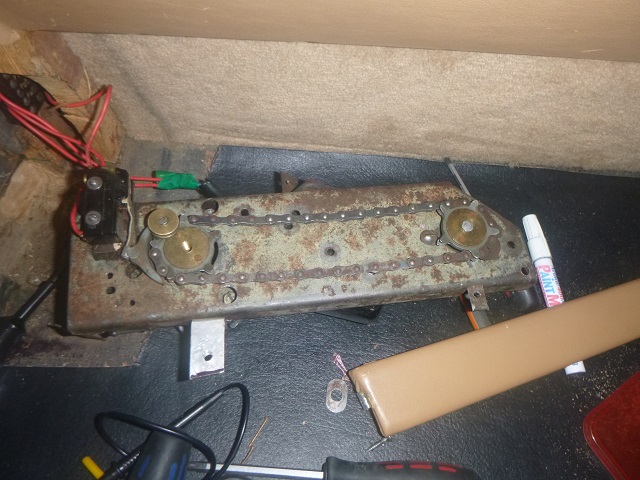 Cheers John Rowney | ||
Dr. Robert N. Moore Yet to post message Username: lewisandmoore Post Number: 1 Registered: 01-2013 |
Hello. I am very much not qualified to comment, but the picture reminded me of the rear blind mechanism of my 1948 Silver Wraith WDC6 Hooper Teviot. The original mechanism was not available to be rebuilt, but I had mine rebuilt with new components by Bentley Zionsville in Indiana, USA. | ||
Jim Walters Frequent User Username: jim_walters Post Number: 306 Registered: 01-2014 |
I think you are missing a switch at the right end. They are limit switches, once the chain block gets around to it the power to the motor shuts off. They are normally power on, but off when depressed by the chain block. There should be one at both extremes of movement, one to shut off power when the blind is fully raised and one to shut it off when it lowers to the bottom. Of the 4 wires going out of the picture, two are for up and two are for down. They swap the + and - volts to the motor armature and field so it runs one direction for up and the other for down. Look at a wiring diagram for a Silver Cloud electric window, it will show how yours should be wired. I'm assuming the wires wrapped in green tape go to the motor? SRH8505 SRC18015 SRE22493 NAC-05370 www.bristolmotors.com | ||
Mark Herbstreit Frequent User Username: mark_herbstreit Post Number: 208 Registered: 05-2005 |
Is it possible the motor runs in one direction? The cord gets pulled to the end of the loop. Spring tension on the blind then takes over to retract as the loop comes back around? It is then up to the chauffeur to decide how much blind you get. No limit switch no reversing motor? I am happy to be corrected. I have the same job to do on WRB60 which is missing all the mechanism under the parcel shelf. I was thinking of us using an electric aerial motor and raiding the mechano set. I watch with interest. | ||
John Rowney Experienced User Username: johnrowney Post Number: 70 Registered: 02-2015 |
Thanks Robert, Jim and Mark. I have yet to fully digest all your comments - I am a bit slow these days. I was fortunate enough to get some interesting articles from Tom Clarke overnight, who is always an absolute wealth of knowledge particularly on the Wraith (after all he did write the Wraith Bible). The most relevant item was the Patent for Piper window blind which is given below. The quality of the images is a little poor, but I don't know how to upload a PDF - I just had to photograph the scanned pages and reduce the pixels of the photos as normal. If anyone is interested in a decent copy I can email you the document scan. Please contact me at johnrowney@bigpond.com 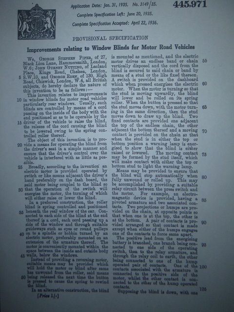 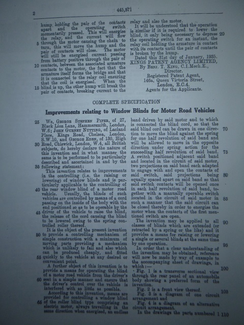 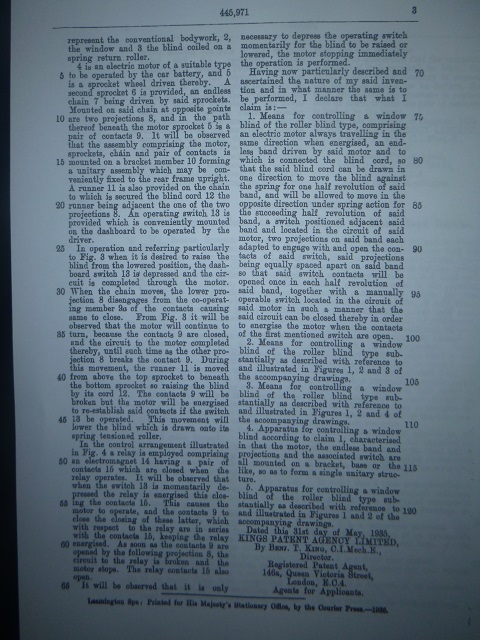 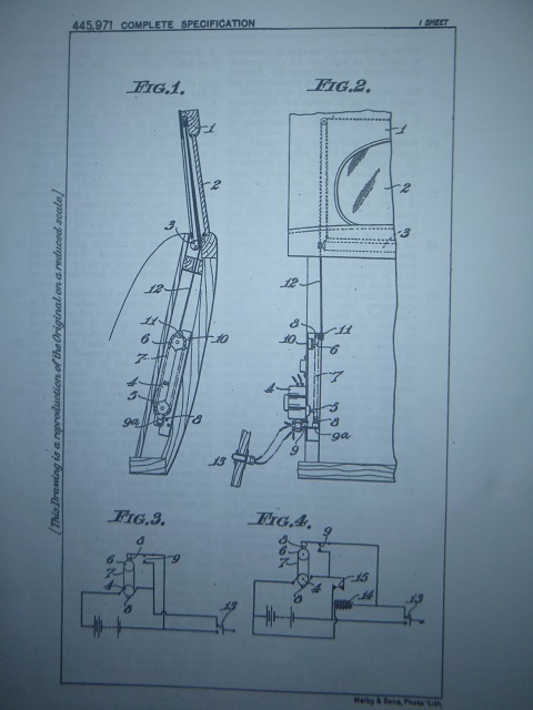 The patent exactly describes the main mechanism I have in WXA68. I am still trying to fully understand the patent, but it appears that I have a system described by figures 1, 2 and 3. My electrical testing this afternoon confirmed that the contactor (number 9 in the patent) was not functioning as it should - ie it was broken and not switching on and off. These particular contacts are still available - a microswitch by Honeywell - number BZ-2RW82-A2. I have ordered a new microswitch from RS Components Ltd in NSW and expect this in a couple of days. I will have to replace a roller fitting at the end of the switch lever of the microswitch with the nylon curved fitting shown in my earlier photo. Jim: I don't think I am missing a switch at the right end. The patent has only one switch. I am assuming there is not the electromagnetic switch as shown in the patent figure 4 ( Ie items 14 and 15). My early look at the wiring does not have any evidence of an electromagnetic switch. Mark: I think that your thoughts of the motor running in one direction are correct. My biggest problem is now trying to sort the wiring on WXA68 out. Lots of it is hidden and it will take me a few days to sort out. I will have to rip out the front seats etc to see what is really installed. John | ||
Dr. Robert N. Moore New User Username: lewisandmoore Post Number: 2 Registered: 01-2013 |
Picture of rear window blind on WDC6 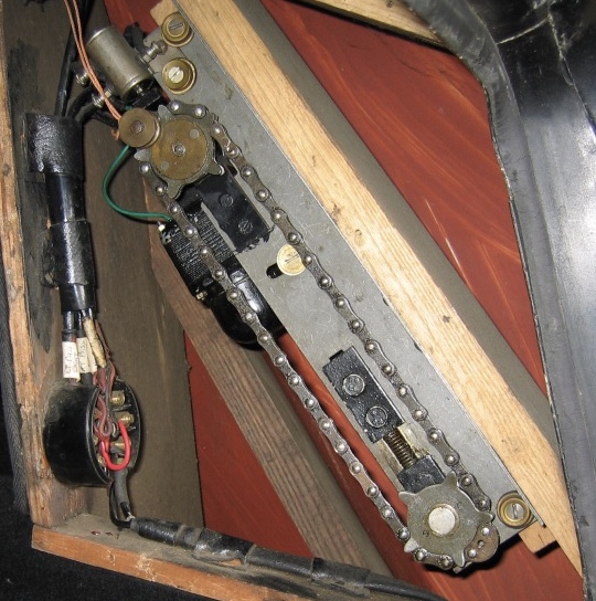 | ||
Mark Herbstreit Frequent User Username: mark_herbstreit Post Number: 209 Registered: 05-2005 |
Its amazing that such detailed info still exists! I haven't had time to digest it all yet but it seems the motor runs in one direction. It may have one limit switch with maybe a contact point at the far end as Jim suggests. You push the button once for up then once again for down. I was thinking you may need to hold the button for a continual loop but a single push is much more Rolls-Royce. Also Dr Moores photo suggests two cords. They would obviously need to come though a common pivot point for an even pull. John, you refer the cord on WXA68 as singular. Is it trying to pull from one side of the blind only? | ||
Jim Walters Frequent User Username: jim_walters Post Number: 307 Registered: 01-2014 |
OK so my guess that it operated the same as electric window lifts was wrong. Makes sense to me now that the motor only runs in one direction with two bump stops on the chain. It stops at up and stops at down. Thanks John for the documentation and Robert for the image, very informative. Mark, you could easily build a similar system to the Piper using a Shadow window motor, gearbox, and chain. SRH8505 SRC18015 SRE22493 NAC-05370 www.bristolmotors.com | ||
John Rowney Experienced User Username: johnrowney Post Number: 71 Registered: 02-2015 |
Robert: Your system looks a bit more sophisticated than mine, and simpler. I am still a little confused about how my electrical system works - hopefully I will sort it out soon, particularly when I install the new mircroswitch. Mark: See the sketch below. 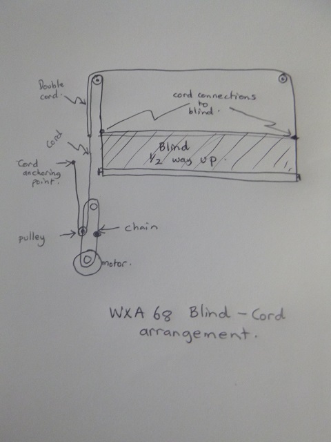 The sketch is for the blind in the half way up/down position. From the sketch the following can be noted. The cord on WXA68 is not attached to a stud on the chain, but is anchored above the chain mechanism and passes around a pulley. This means that the blind travels twice the distance as that travelled by the chain. The cord is joined by a second cord. Each of these cords goes to its particular side of the blind, ensuring smooth travel of the blind. John | ||
John Rowney Experienced User Username: johnrowney Post Number: 72 Registered: 02-2015 |
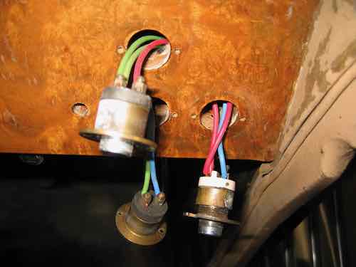
I started trying to find what I actually had as far as wiring goes for the blind today. I started at the front seat. After demolishing a substantial part of the seat and supports, I realised I would have to start on the other side of the division. The radio was taken out, carpet ripped off a timber piece and the timber piece removed. Here is what I saw in the area where the chain etc was located. 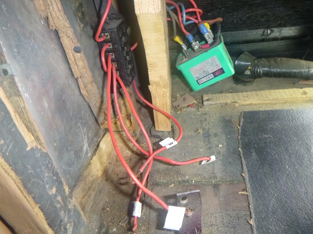 There was the wiring I have shown in a previous photo, but there was a green thingo, which seemed to be a relay, with myriad wires. The diagram on the relay is shown below. 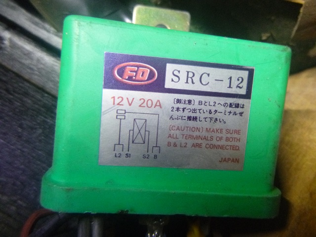 I checked the website for FD, which turned out to be a Japanese company which makes an immense range of electrical devices. The closest I came to my relay was SLR-12B, whereas mine must have been the earlier SRC-12. A photo taken from the FD catalogue showing SLR-12B is given below. 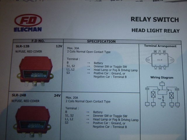 Obviously the relay I have in WXA68 is much simpler than this one, but it suggests that my circuit must be something like figure 4 of the patent. Unless of course the relay is more involved (as the multitude of wires suggests) and it could even reverse the motor current (?). Any advice offered will be greatly accepted. I must admit that, at this stage, I am inclined to replace the microswitch when I get it and put the whole jolly lot back together again. Getting the terminal section and the relay out would require a massive demolition of the remainder of the back of the division, which is not appealing. It will take a while to put the seats, timber, radio and carpet back together again as there are the normal amount of screw holes to be filled and redrilled and new screws sourced, as well as trying to locate all the bits I have mislaid in the incorrect containers. Strewth! Never a dull moment during these Covid-19 times when we are all supposed to be bored out of our wits. I suggest to mates that they blow some of their superannuation and buy an old Rolls-Royce and they will never be bored again! Cheers John | ||
Dr. Robert N. Moore New User Username: lewisandmoore Post Number: 3 Registered: 01-2013 |
 . . Division pushbutton switches on left. One up, one down. Single blind pushbutton switch on right. Push once, blind closes. Push again, blind opens. | ||
John Rowney Experienced User Username: johnrowney Post Number: 73 Registered: 02-2015 |
Hi Robert I looked at my blind switch the other day, and it has only two wires. Since it has been over 12 months since the car has been driven, my memories of how it operated are vague. However, I recall that I had to continually push the switch to keep it going. There are also parallel switches for the rear passengers. The glass division switches act the same as yours. These are also duplicated for the rear passengers. John | ||
Jim Walters Frequent User Username: jim_walters Post Number: 308 Registered: 01-2014 |
John, yes it should work with just two wires at the button if the relay and microswitch are wired correctly. The microswitch will be wired with contacts normally closed putting power to the relay to energize it and therefore the motor when it is not activated by the chain bump. With the blind either up or down the chain bump will open the switch contacts cutting off power to the relay stopping the motor. When the button is pushed, it puts 12V directly to the relay overriding the switch, closes the relay contacts and the relay then gets power to start the motor. Once the first chain bump has moved off the switch, the switch is on and the motor will continue to run until the second chain bump hits the switch and turns off power to the relay and the motor stops with the blind in the up position. Push the button again and the same operation happens until the second chain bump opens the switch contacts again shutting off the motor with the blind now in the down position. You do not need the motor to reverse direction. Wired this way the blind can only be up or down, not half way. If you bypassed the microswitch and wired the button directly to the relay, you would have to keep the button pushed to keep the blind moving, and be able to stop it at any position. With the microswitch wired in as described, you only have to push the button momentarily until the chain bump moves off the switch and the motor will then run until the second chain bump shuts it off. Goes without saying that you can't trust any of the wiring there nor the relay, none of that is original. A simple common Bosch relay as used in the modern cars will work just fine. If you need a clear wiring schematic, give me a day and I'll sketch one up for you including the second rear seat button. Pretty simple really. SRH8505 SRC18015 SRE22493 NAC-05370 www.bristolmotors.com | ||
John Rowney Experienced User Username: johnrowney Post Number: 74 Registered: 02-2015 |
Jim: Many thanks for this. I have just picked up the microswitch and will test the existing circuit today and see what happens. If I get the system to work correctly, I think I will avoid doing anything else. However, I will await your circuit with keenness. I am still a little hesitant redoing all the circuit since it will be such a dismantling job for rest of the division wall. | ||
Jim Walters Frequent User Username: jim_walters Post Number: 309 Registered: 01-2014 |
Here it is, wired this way with one quick push it goes all the way up or down. Very simple to wire up and you can probably use some of the wires already there. If you want to be able to control where it stops just bypass the microswitch. Then you have to hold the button down steadily to operate the motor. 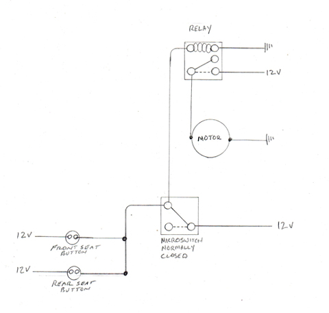 SRH8505 SRC18015 SRE22493 NAC-05370 www.bristolmotors.com | ||
John Rowney Experienced User Username: johnrowney Post Number: 75 Registered: 02-2015 |
Jim: Many thanks for the drawing. It looks very straightforward. The other day, I thought I would try to pull out the rear timberwork of the division to get access to the wiring of my rather complex system. In the end I had to give up - I would have to take the whole division out to remove the single piece of timber in the way. This sits between the wiring terminal block and the relay. In addition the myriad wires disappear into a wrapped wiring loom which then disappears into the bowels of the car. I am not willing to tamper any further, particularly since lots of wiring to the motor, horns, lights, starter etc is disconnected and could give shorting problems if I reconnected the battery. I have ordered a new cord and will put everything back, including the new microswitch and test it once the engine is fully installed and the car back running again. I hope that in about 6 months time I will get back to the blind mechanism, and put Jim's straightforward system in place, by running new wiring. Many thanks for everyone's contributions - much appreciated. Sorry to disappoint at this stage by not continuing on with completely sorting the division blind mechanism. WXA68's engine is sitting on my palette mounting system in Sydney, just waiting for the cylinder head to be returned from a sole sub-contractor who has significant family health issues. He has had to delay finishing the head off as a result of these issues. Hopefully I will get the engine back very soon, and serious work can then start. John | ||
John Rowney Experienced User Username: johnrowney Post Number: 76 Registered: 02-2015 |
I have now got the blind system back working, but with only temporary power to drive it. I will wait until I have WXA68 back on the road with all the electrical system restored and test the operation of the switches for controlling the blind. If it isn't the "Rolls-Royce" quality of Jim Walters' scheme, I will then put in Jim's straightforward scheme. To get the system working well, I had to overcome the following problems since my last post. The cords in the double pulley between the roof and the headliner were jammed. This meant removing more timber work and opening up the headliner. I then had to remove the double pulley to un-jam the cord. After this repair, I found that the blind itself didn't have enough tension to smoothly rewind fully, so I gave the tensioning axle an additional turn. Once this was done, the blind moved up and down easily under manual action. However, when I put the chain drive back on, the cord jumped off the pulley on the chain. After lots of thought, I finally found the original anchoring point for the end of the cord. This was very close to the top of chain drive, but the position was very difficult to access. This lack of easy access is probably the reason the cord was located at the more remote, but accessible location. Anchoring the end of the cord at this original spot eliminated about 600mm of cord and eliminated its tortuous path which was often hidden behind framing and other obstructions. With the original anchoring point being used and after the chain and motor were re-installed, the system worked extremely well using my temporary battery power. It was great to see the blind smoothly rise up and then retract under power - at last! The timber and carpeting have now been fully replaced, and I will wait with anticipation the ultimate test after the engine is installed and the electrical system is fully operational. This has been quite a learning experience. Many thanks to everyone for your suggestions and comments. I still don't know when the car's motor will have its rebuild finished, so the definitive test of the blind may be a few months away. | ||
John Rowney Experienced User Username: johnrowney Post Number: 94 Registered: 02-2015 |
I have almost got WXA68 completely running again, but I have had quite a few long periods where I had time to completely rewire the blind mechanism using Jim Walters' suggested wiring. What a mission! All the original wiring looked original and would crack or break at first touch. Only the wiring for the blind looked like it was original and the the rest of the wiring - eg the division glass up and down wiring and the interior light wiring, were obviously renewed with plastic wrapped wiring in the 1980s. Unfortunately all the wiring was in a wrapped bundle of wiring from every switch and joined myriad other wires as it snaked through the chassis and the body of the car. A kosher rewiring would require a body-off restoration - this is not a job for this aged custodian. Perhaps the next custodian will completely rewire the car. The only thing I could do was chop off each end of the wires and completely re-wire the blind system. This was a major task. Problems included trying to thread new wiring through almost impossible paths through armrests, side panels and the dashboard. The worst was trying to access the original relay which was located behind a board which had carpet glued to it which made access somewhat difficult. By various means, I managed to cut a hole in the timber after painfully ripping off the carpet. I then extracted the old relay and then started the rewiring. A week later, and after much cursing and swearing the wiring was done. So far so good. The new relay (occupying about one eighth the volume of the old relay) was relocated in a handy position under the floor along with the wiring terminal block. No more demolishing parts of the car to access any of the system! I assembled the mechanism and tested things out. After a couple of cycles everything came to a grinding halt. A very thin nut which holds to top gear wheel in place had somehow disappeared and could not be found even after an 8 hour search. There was only about 1 and a half threads available for a nut, so I made up a makeshift metal epoxy substitute. The next day, upon testing after a long curing period this fell off. However, Araldite was to the rescue and I Araldited the epoxy substitute in place. Once back together, everything worked well. Looking at Robert Moore's photo, it would appear that a similar epoxy substitute nut may have been used in a similar installation on WDC6. Many thanks to Jim for his simple, but very effective solution. For the first time since I have owned WXA68, the division blind now goes either up or down with one push on any one of the 3 buttons in the car. I must admit a sense of achievement to get this working well and actually can't resist pushing the buttons a few times every day to convince myself that it actually works like it was intended. Many thanks for everyone's suggestions and comments. | ||
Larry Kavanagh Frequent User Username: shadow_11 Post Number: 695 Registered: 05-2016 |
Well done John, I can empathize with your sense of achievement especially after the painstaking and time consuming effort that went into it. Regular button pressing should help to keep the mechanism working freely. I would probably get up in the middle of the night just to satisfy my insatiable desire to confirm that the blind division is still functioning as designed but perhaps I'm slightly mad. | ||
Theo Whitmont New User Username: old_mate Post Number: 27 Registered: 04-2020 |
Gents, I have enjoyed watching the evolution of this post - it is the embodiment of everything good in this forum. The technicalities of some of the posts were well beyond me but with persistent google searches to close the gaps I have increased my knowledge and gained a little confidence to push further in the work on my old girl. So thanks to all. I suppose the reason for my post is to highlight the value of the forum not just for the active participants, but also for the sometimes silent onlookers. Best wishes to you all! | ||
Jack Higginbotham New User Username: jhinmd Post Number: 41 Registered: 11-2017 |
Theo, I could not agree with you more. I have enjoyed this thread, learned from it and I am certain I will also benefit from this in the future. This is a fantastic community, and even though I don't post often, I love the conversations and being part of this group. I am caretaker of WXA99, and I have wondered exactly how the beautiful division window operates...this is fantastic stuff! Thank you all for sharing your knowledge. | ||
David Gore Moderator Username: david_gore Post Number: 3842 Registered: 04-2003 |
For everyone who has contributed and those who have followed this project out of interest. This is what keeps our forum alive and our members contributing when they can help out. Thank you one and all. |