| Author | Message | ||
Richard Treacy Grand Master Username: richard_treacy Post Number: 1982 Registered: 4-2003 |
Let me share an Industry Secret. On all cars, there is always a possibility that a fuse, wiring or switchbox defect in the ignition circuit will stop you in your tracks. This happened some weeks ago on our T-Series, although it fixed itself immediately upon restarting. However, the consequences of the temporary, probably one-off, failure were so alarming that I had to do something definitive before it could happen again. I put a temporary fix in place when the switchbox malfunctioned due to a dirty contact. However, I now consider it an essential modification for all our cars. I dismatled and ensured that the switchbox is not a risk anymore, but have now installed the mod in two Turbo R's including my everyday-driver, my R-Type and T-Series alike. If the ignition circuit fails, you will lose engine RPM at low speed and stall when the torque converter or fluid flywheel has insufficient drive to keep the motor turning. The steering loses its power assistantance on SC cars onwards, and distaster may occur. Those with shot SY or SZ accumulators will also lose braking completely. Earlier cars may be safer, but will also break down in the middle of Woop-Woop. Simple. Fit a relay as shown below. There is no change in functionality whatsoever. If a benign ignition system failure occurs, you will certainly noitice it upon starting as the ignition lamp will not illuminate immediately. The car will function properly, and you will safely have time to make a full repair in the coming weeks. However, once running, the system will not stop despite the failure. You may drive home safely without crashing unexpectedly. The relay bootstraps the ignition in a very safe manner, and may avert a disaster. It drops out every time you turn off the ignition. It will fit very neatly in the fusebox on all cars. It is such a simple and low-cost safety improvement that we cannot afford not to implement. RHT. 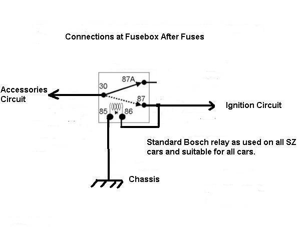 | ||
Paul Yorke Grand Master Username: paul_yorke Post Number: 447 Registered: 6-2006 |
Richard, Fine modification . . . but what would happen if the - rotor arm, coil, ballast resistor, fuel pump, King lead, fuel line, wiring or connection in either the ignition circuits or fuel pump circuit - fails? or indeed, if you just plain and *simple* run out of fuel!?!? Those with shot SY or SZ accumulators will also lose braking completely. Better to fit new accumulators and sort out your real emergency backup! | ||
Richard Treacy Grand Master Username: richard_treacy Post Number: 1983 Registered: 4-2003 |
A very strange response indeed. Perhaps it is an answer to another topic. | ||
Richard Treacy Grand Master Username: richard_treacy Post Number: 1984 Registered: 4-2003 |
An improvement just done is to include a diode as shown below. The diode preserves discrimination between the fuses. It also prevents any sort of system failure in the accessories circuity from affecting the ignition. That is very useful, as the ignition system is safety-related whilst the accessories system is virtually not. This slight change increases the MTBWSF of the ignition circuit to a level way above original. Note that, in the same pursuit, SY cars and SZ cars until Chassis 20,000 have a safety relay in the headlamp system to preserve lighting in the case of an electrical failure in the main circuit. There is nothing new about safety relays intended to save lives in case of an unexpected system failure. RHT. 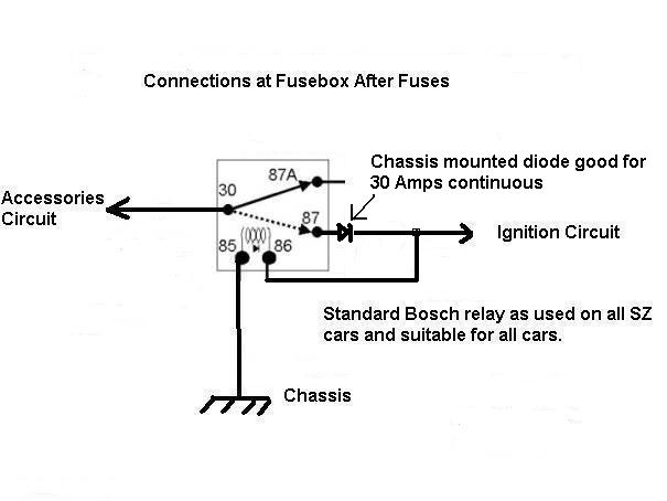 | ||
Colin Silver Frequent User Username: colsilver Post Number: 98 Registered: 8-2008 |
Richard, can you simplify this for me. My late Father In Law tried to teach me things like this but only a fraction got through. Is the relay used to automatically switch to another power circuit on failure of the original? If so, from what to what. Thanks. | ||
Richard Treacy Grand Master Username: richard_treacy Post Number: 1987 Registered: 4-2003 |
Colin, When you switch to Accessories, the relay does not pick up immediately. Thus all is as it was unmodified. Once you switch to Ignition On, the relay picks up and latches until the key is switched back to Off. In other words. the relay will only energise once the ignition is turned on, and will then stay energised until both the accessories system voltage and the ignition system voltage are removed. Once the motor is running, the ignition system will function properly whenever either the ignition system or the accessories system is functional. Under normal conditions, the relay carries no current by virtue of the 0.7V drop across the diode. The fuses carry their normal currents, and safety protection is not affected at all. If the fuse or circuit breaker in the Ignition circuit fails while the motor is running, the relay takes over the current load through the diode. Thus a wrong side failure is averted in case of a benign failure in the system, such as a bad contact in the main switchbox, a faulty breaker, a dirty fuse or whatever. Thus, the relay improves the system integrity enormously. Once the motor is stopped on the key, the relay drops out. The relay will not latch unless the ignition circuit is energised. Hence, the motor will not start until any fault stopping ignition voltage is corrected. However, the vehicle does not stop dead while driving, hence avoiding a wrong side failure (in other words, a potential accident). The ignition system MTBWSF (mean time between wrong side failures) due to loss of system voltage through the types of faults noted above is safely increased by a factor of at least ten. The relay can avoid danger in case of an intermittent ignition system fault. Intermittent faults are so common and so dangerous in trains, planes and automobiles that some insurance is surely a good thing. Of course, the fault itself would need attention as soon as possible. Should a failure occur in the accessories system, then the diode ensures that the ignition system does not feed the accessories. Hence, the integrity and safety of the ignition system is unaffected if your cigar lighter is jammed on or your DVD, or whatever, blows up for example. With just two wires and a chassis connection to be made, this modification could not be simpler to implement. RHT. | ||
Richard Treacy Grand Master Username: richard_treacy Post Number: 1988 Registered: 4-2003 |
More simply: � The relay picks up and stays energized whenever you turn the ignition on if the ignition system is functional. � The diode carries no current when is all is well. � If the feed to the ignition circuit fails while running, the accessories circuit takes over through the diode. The diode voltage drop is 0.5V to 0.7V. � The accessories circuit fuse has ample capacity to feed the ignition system � The relay de-energises whenever you switch to Off. | ||
Paul Yorke Grand Master Username: paul_yorke Post Number: 448 Registered: 6-2006 |
If I'm understanding it correctly, This diagram might make the circuit more obvious. 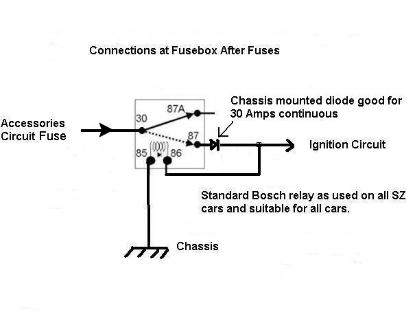 And if I am understanding it correctly . . . I'm not convinced about the protection the ignition circuit will receive in the case of a NON benign fault. If an ECU or Ignition module starts to become faulty and draw extra current, will it now draw from both the Ignition feed and the accessories fuses, thus loosing their protection for anything but an almost dead short? Perhaps it would be better for Pin 87 to go to the input side of the ignition fuse instead? or at least fused separately. Also make sure that you pause when going from engine running to accessories. | ||
Patrick Lockyer. Grand Master Username: pat_lockyer Post Number: 816 Registered: 9-2004 |
Trade secret. Keep things simple! it is an old T series after all. Find the route cause of the fault,ie connections and maybe the start of ballest resister fault. common to fail when hot if showing a high resistance. Do not be clever with sticking electrical mods on. This causes much probs in later years when the younger generation come to take on the cars,useing the offical manuals will not relate. Add on relays and the like can fail why add on in the first place,if a electrical problem exists fix it. Trade secret for the clever but not practical type! Get it on the oscilloscope,will show the many other failings that Paul has mentioned. Hope this will help RT get his feet back firmly in OZ with the old girl. | ||
Richard Treacy Grand Master Username: richard_treacy Post Number: 1991 Registered: 4-2003 |
Paul: Cripes. This is for benign faults as noted above. An avoidable dire consequence of a benign failure is better than an accident surely. An ignition system short or total failure below 60 km/h will kill you anyhow when the heavy steering drives you off the road. As for a delay, that would be enough to stop the motor and to kill you through extremely heavy steering anyhow. Heavens: another fuse ? The diode is there for a reason afterall. The diode stops an accessory meltdown from blowing the ignition fuse. Patrick: As stated, this is a safety relay to allow you to live long enough to stop and have a repair done properly. Also, the T-Series has a few more wires than three. An oscilloscope for diagnosis of a continuity issue after you die is not much consolation when a multimeter does a better job. This is such a simple safety measure that I am surprised at the hostility being vented from the Island near the Atlantic. RHT. | ||
John Kilkenny Frequent User Username: john_kilkenny Post Number: 90 Registered: 6-2005 |
Before there is a rush to fit Bosch relays to all our cars it would be useful to determine the level of protection being achieved by the suggested modification and whether the likelihood of the fault occuring justifies the corrective action, which resulted from one particular electrical fault on one car. The only device that is really being backed up is the ignition section of the key switch, and failure of wiring and all equipment after the new relay is not covered. With regard to the fuse protecting the ignition, because it is constantly passing current it is unlikely to fail due to poor contact. If it fails due to a frame short circuit or overcurrent situation it will most likely blow the accessories fuse as well, when this modification is fitted. Also of course the new added wiring and relay might also cause future failure if not properly done. While failure of the key switch (like any other switch) can occur it is generally when the switch is being operated rather than after the contacts have been made. It would be interesting to hear about other users' experience re failure of the key switch. | ||
Paul Yorke Grand Master Username: paul_yorke Post Number: 450 Registered: 6-2006 |
Richard . . . you seem to be in a complete panic about one fault that could lead to you loosing power steering and brakes. And seem shocked as though it is the worst thing in the world that could happen. In my life of driving I've lost engine power countless times 50+ easily. (remember I am in the repair industry and drive sick and dying R-R & B's more than most) "An ignition system short or total failure below 60 km/h will kill you anyhow when the heavy steering drives you off the road. As for a delay, that would be enough to stop the motor and to kill you through extremely heavy steering anyhow." Well either I'm dead and risen - or you really should not be driving in your fragile condition!! Yes it gives you the willies but plenty of things will do that. Get your accumulators sorted and keep your brakes in good condition! If your engine cuts out - restart it or stop the car. I felt that you're trying to fix a rare and minor fault which occurred much less frequently than opthers, SO I asked you "what would happen if the - rotor arm, coil, ballast resistor, fuel pump, King lead, fuel line, wiring or connection in either the ignition circuits or fuel pump circuit - fails? or indeed, if you just plain and *simple* run out of fuel!?!? You say - "A very strange response indeed. Perhaps it is an answer to another topic." Simple answer - the engine will stop and you will lose your power steering. Add to that fan belts breaking, PAS hose bursting, and a bag full of others faults with nothing to do with an ignition fault - which according to your scenario, would make any car unsafe to ever drive! you say " Heavens: another fuse ? The diode is there for a reason afterall. The diode stops an accessory meltdown from blowing the ignition fuse." Yes – the diode will stop accessory faults blowing the ignition fuse . . . but that is not my worry. I'm more concerned about the reduced (halved at least) protection to the ECU's etc . They will now be able to draw current from both the accessory fuse AND the ignition fuse at the same time. What may have been a small and repairable fault now means a burnt out and unrepairable circuit board instead. I'm all for improvements and modifications - but all things considered, I feel this is backwards step as the cons far outweigh the pros. PS - Relax Richard, I don't think anybody is 'venting' anything, just exploring the advisability of the MOD. I think you are mistaking our incredulousness for hostility. | ||
Richard Treacy Grand Master Username: richard_treacy Post Number: 1992 Registered: 4-2003 |
No panic. Afterall, many decades have passed since we all read about switchbox failures and how to repair them. As an analogy, I have never needed to wear seatbelts, but I do. I have never needed a crash helmet on a bicycle, but they are the law too. Not that the law is wrong in these cases in my opinion. No interpretation or crystal ball analysis is required either, nor do we all need to be told what we are really thinking, let alone transform this particular topic into an unrelated leacture about ECUs and accumulators. | ||
Richard Treacy Grand Master Username: richard_treacy Post Number: 1995 Registered: 4-2003 |
and if you look at the fuse discrimination dictated by the diode, the protection, primitive as it is in all automobiles, for everything in both the accessories and ignition circuits is not altered in the slightest. If anyone is worried about fuse protection, maybe semiconductor-rated fuses and HRCs as we use in industry may be substituted. | ||
Paul Yorke Grand Master Username: paul_yorke Post Number: 452 Registered: 6-2006 |
Richard, I'm sorry if you feel like you've been bombarded on this post, but I think the main problem was the over descriptive perception to the dangers of this one (and IMHO, rare ) fault. Maybe I'm interpreting your circuit wrongly. My concern was based on the assumption that you meant the extra feed is coming from the *switched* accessories fuse which is most often different to the ignition circuit fuse. | ||
Richard Treacy Grand Master Username: richard_treacy Post Number: 1996 Registered: 4-2003 |
Cripes, a little simple suggestion has become tedious. Basic electrical design principles apply in the form of fuse discrimnation analysis. Let's look at an SY for example. http://rrtechnical.info/sy/tsd2476/13.pdf page 7. The main switch accessories and ignition circuits are each protected by individual 22 Ampere Master Fuses. Those are the open ones with replaceable fuse wires (1 strand only). They are known to corrode or be a little dodgy when owners are hamfisted. They are slow to blow, and only offer crowbar-style protection in case of a massive short circuit. The relay/diode pair joins these electrically ONLY if the ignition system voltage is about 0.7 Volts lower than the accessories one while the motor is running. Downstream, the master ignition system branches out into separate subsystems, each protected by fuses of a lower Ampere rating. The main ignition subsystem is itself protected by its own 10 Amp small glass fuse. The ignition circuit is fully protected alone by its 10 Amp fuse, and that has not changed. The 22 Amp Ignition Master Fuse is the protection for the entire system switched by the ignition switch when activated by turning the key to the Ignition On position. If a short occurs between the ignition subsystem fuses and the Ignition Master Fuse, then the Ignition Master Fuse will blow, followed by the Accessories Master Fuse microseconds. That will not be the case if an ignition subsystem has a fault. If there is a fault in the ignition subsystem itself, then only the faster, and lower Ampere rated, glass 10A fuse will blow. Again, no change. I assure you that there is no degradation in fuse protection, and only a vastly improved system MTBWSF. Sure, other nasty wrong-side failures may occur, but they addressed by rigidly scheduled maintenance. MTBWSF is achieved usually either through relaibility or through maintenance. All your fan belts and other critical bits are scheduled replacement items, other vital bits are tested during scheduled maintenance and so on, but I have never seen a service schedule to replace the fuses or wiring, or to overhaul the switchbox. They can fail anytime, and a backup like even the headlamps already have must be a positive step. | ||
Paul Yorke Grand Master Username: paul_yorke Post Number: 453 Registered: 6-2006 |
Richard thanks for running through that more fully. Don't take this the wrong way I'm only trying to sort this out in my mind. I'm not an electrical engineer by any means, but over my lifetime on R-R's I've tried to pick up some knowledge and get by pretty well. I'm also very happy to ask peoples advice when I don't know something - 'A day without learning something new' is a wasted day in my opinion. Anyhow . . . Now I'm confused and I'm just asking for my peace of mind. I always thought of a diode as a one way valve. To keep it simple I'm ignoring the continuous and blow rating of fuses and the very slight extra load a diode puts on a circuit. I have always assumed that when a car circuit is protected by a 10 amp fuse the most it could draw (ignoring surges) would be a little over 10amps. Now if you get another 10 amp fused feed and connect it in parallel to the same circuit - the maximum the circuit can draw is now twice as much ie 20 amps And if you do the same again . . . 30amps. Now If we keep the 3 fused circuit with a possible draw of 30 amps and introduced a diode into the first fuse circuit, I always assumed that the maximum possible draw would still be 30amps . Ditto if you add diodes to the second and third fused feeds. Obviously a dead short to ground will blow all three fuses - but would say a 25 amp draw any of the fuses? maybe my analogy of a diode as a one way valve is too simple and I'm missing something here? Thanks in advance. | ||
Richard Treacy Grand Master Username: richard_treacy Post Number: 1997 Registered: 4-2003 |
Paul, A diode is indeed a one-way valve, but with a small series resistive and fixed voltage drop when ON among other characteristics. For example, typically a conventional silicon power diode will start to conduct at about 0.5V, conduct well in the operating range at maybe 0.8V, and burn up at 1V. It is very useful in this application, because a voltage drop elsewhere in these local circuits of greater than 0.3V is uncommon unless there is a problem. The 0.8V drop across the diode is key to the safety of the protection in this case. In more spread-out circuits, for good measure two diodes may be used in series to give a voltage discrimination of about 1.6V. Back to the SY case. Concerning the 22Amp Master Fuses. The relay does not place the fuses in parallel. Sure it looks quasi-parallel, but never do the fuses share current between eachother. Only if the ignition circuit loses voltage for any reason, the aim being to look after benign errors such as a loose wire or switchbox contact, is the Ignition Master Circuit fed by the fused Accessories Master Circuit. In that case the ignition system load is not shared by, but rather completely diverted to, the Accessories Master System and protected by its own (ie 22A) Accessories Master Fuse. In that case, whether blown or not, the Ignition Master fuse is not electrically part of any circuit. On the SY example, both fuses have a 22Ampere nominal value. With the diode-relay applied, neither system has the possibility to draw more than the nominal 22A without a fuse isolating it. Once the relay closes, the output ends of the two 22 Ampere Master Fuses are both at battery voltage and therefore isolated by the diode. Should the Accessories Master Fuse blow, the diode remains blocked and keeps the ignition master circuit isolated and functioning. If the current in the Ignition Master Circuit exceeds the nominal 22 Amperes, it will blow the Ignition Master Fuse. Only then does the accessory circuit take over, as only then is the diode forward-biased enough to feed the ignition circuit. Should the Ignition Master Circuit still exceed 22A nominal after its fuse blows and the diode conducts, then the accessories master fuse will blow. That is a minor nuisance compared to losing motive power. Note that, at all times, the fuse protection remains at 22A, and never 44A +/- as it would be were the fuses simply electrically paralleled. Downstream, no fusing is changed. For example, the SY still has its 10A quickish glass fuse for the ignition subsystem (coil etc), and nothing has changed. This 10A fuse is the sacred cow, as is every fuse closest to the final device it powers. The same applies to other devices connected from the Ignition Master Circuit. Most devices in these cars have their own even smaller fuses either in-line or internal: DVD player, fuse inside the clock and so on. ECUs generally have special protection including inbuilt surge suppression, but also a high speed thyristor grade fuse and thryistor crowbar setup. However, if an ECU fails there�s not much help from any external fuse, so protection of an ECU by a fuse in a fusebox is almost a contradiction in terms. Fortunately, I recall that only the ignition ECU can stop the motor instantly on cars from early Lumenition SYs until Zytek SZs. Earlier SZ cars and SYs are fine in the fuel department until the fuel pump runs flat if its fuse blows, as they have mechanical fuel injection or carburettors and electrics only to tweak them. It's the same in a home. If your bedside clock blew up, you would be annoyed if the main breaker to the house tripped out, let alone the whole street at the substation. The clock itself may be fused, and at worst the room. If the clock is fused, then that and only that fuse should blow. | ||
Paul Yorke Grand Master Username: paul_yorke Post Number: 454 Registered: 6-2006 |
Thank you for that explanation Richard, that all works pretty much as I thought. My next question, if you have the time, is about running a circuit at a load level where it is about to blow the fuse but not quite there yet. Using your 22A examples. In the workshop, I find that if there was a problem with, something on the ignition circuit where, say, an ECU was failing, a good way of checking for problems is to either connect an ammeter in series with the fuse and measuring the current or, and more easily, Use a volt meter on the suspect circuit and compare that to an unloaded circuit (battery voltage) . You can then tell instantly by the voltage difference, that the circuit is overloaded and start searching for the fault. That voltage drop can be as much as two or three volts. In this scenario, from your explanation, it seems that the voltage difference between the Ignition circuit and the accessory circuit would be high enough for the Ignition circuit to start drawing from both circuits/fuses at the same time and therefore be able to draw up to 44A. In my impetuous youth I've tried to locate faults by uping a fuse rating to give you more time to find a fault. I soon learnt that it was not a good idea when my brand new amp went up in flames and almost took the car with it! I got out of that habit pretty damn quick but We occasionally get various ECU's in for repair that have fried out circuit and useless circuit boards - when quizzing the client, the common (and sheepish) answer is either upping fuses or home made 'power probes'  Although many units have some sort of protection built in, often over loading is caused by 'unplanned' mechanical failure, perhaps due to condensation or steam cleaning, or maybe even just a piece if solder or swarf that is kicking about and shorting a circuit. Doubling up of fuses in these cases can be disastrous. Just as another side thought. (but kind of returning to the original topic fault) If there was something overloading the circuit but not blowing the fuse yet, then the first thing to suffer would be make / brake connections such as relays contacts and more significantly, ignition switch contacts. Possibly showing up as an intermittent connection? Like I said, just a thought. | ||
Richard Treacy Grand Master Username: richard_treacy Post Number: 1998 Registered: 4-2003 |
Hallo Paul, I agree wih all that you write in principle, but I must make a qualification. The switchbox is fed by a single power trunk. Through the switch ACC and IGN are separated, and a heavy cable from each branch feeds the fuse panel very nearby. The voltage drop in those leads would be about 0.1V each on full 22A load as they are so short and of a very low impedance per metre. The voltage drop after that part of the fuse panel is through small gauge long leads, sometimes three or four metres of fine wire, and can be quite some volts even without any overload as such. In other words, the loss of 3V at an ECU etc not unusual and is produced almost entirely after the 22A fuses. For example, see my bits on window relay modifications to include window relays. Without, although the fuse panel may be at battery voltage minus just 0.05V on full load, properly functioning windows may have only 3V left due to those subsequent voltage drops along those long, thin wires. Your method of current limiting with a multimeter is not uncommon. I prefer to use a simple home-made current limiter costing about two quid: a power transistor and a potentiometer in a small box is perfect. You may dial up the current limit value on the pot. The voltage holds up to battery voltage minus one volt until the dialed current is reached, then collapses safely to zero. You may then remove a subfuse at one end, for example the 4A aircon control fuse, attach the box in series with the fuse and the circuit, and test with say a 1A limit. I'll elaborate later if you wish, and draw a diagramme once I am back in Canberra again using for example a 2N3055 transistor and a potentiometer. By the way, fuses have a great problem in sharing loads, hence doubled-up wires of an SY open fuse, each wire rated at 10A, need to be twisted together tightly otherwise they will probably blow at 15A rather than 20A. Bulgin fuses cannot be successfully paralleled to increase a fuse rating, likewise glass or Littel fuses. Paralleled fuses of different ratings or types are a lottery, usually blowing at the rating of the larger fuse and not more. The slightly higher resistance of the smaller capacity fuse diverts almost all the current through the larger. For now, RHT. | ||
Colin Silver Frequent User Username: colsilver Post Number: 99 Registered: 8-2008 |
I've the problem solved, and in two sentences. Catch a bus. Ok, 4 sentences. This is interesting reading. | ||
Paul Yorke Grand Master Username: paul_yorke Post Number: 456 Registered: 6-2006 |
Richard, thanks for taking the time. I think I'll give it a miss because of my concerns - but enjoy the peace of mind it's given you. Colin - catch a bus?? Do R-R & B make buses? - we'll be waiting a while I think! | ||
John Kilkenny Frequent User Username: john_kilkenny Post Number: 91 Registered: 6-2005 |
If anyone can remember how this thread started, I have a question. Is it desirable to add an additional relay, power diode and associated wiring to prevent what is basically the failure of a single very reliable component (ignition key switch) from stopping the engine, when there are many other more likely situations to cause engine failure ? Probably not. | ||
Richard Treacy Grand Master Username: richard_treacy Post Number: 1999 Registered: 4-2003 |
All points taken in good faith and humour. Would you fly an aircraft with no backup systems though ? Maybe I need a Phantom III with its three ignition backup systems. | ||
David Gore Moderator Username: david_gore Post Number: 912 Registered: 4-2003 |
I think it is appropriate to close this thread with RT's comment. As always, it is the responsibility of readers to make their own decisions and accept the consequences of their decisions in relation to the information posted by the various contributors. Thank you to everyone that has contributed - I think this has been a worthwhile discussion notwithstanding some comments which may suggest otherwise. |