| Author | Message | ||||
Geoff Wootton Grand Master Username: dounraey Post Number: 942 Registered: 5-2012 |
Hi Folks I am currently overhauling the coolant level system on my car (SRX18501) and was hoping to get around having to remove the coolant probes in the header tank. This is because, from past experience, I expect them to be difficult to remove and I do not wish to risk damaging them. So, I took a resistance reading between the two probes and to my surprise found it to be quite low. The reading was also variable, moving from 47k ohms to 60k ohms. When I dip the measuring probes on my meter into a container of old coolant (awaiting disposal) I get a variable reading from 10 to 16M Ohms. This reading is what I expected, but not the variability. Does anyone know what resistance should be expected between the coolant probes on the header tank, or why I am not getting a constant, stable reading for either test. Regards Geoff | ||||
Robert Noel Reddington Grand Master Username: bob_uk Post Number: 473 Registered: 5-2015 |
Water doesn't conduct electricity unless it has some minerals and other things. This is maybe causing the eratic readings. Also dirty probes will not conduct as well as clean ones If the system works by disconnecting a probe or via the test button then the system will be fine. | ||||
Geoff Wootton Grand Master Username: dounraey Post Number: 943 Registered: 5-2012 |
Hi Bob_uk Thanks for your reply. Both of my tests were carried out in coolant, not pure water. I just don't understand why the resistance is so low (50K ohms) between the two probes on the header tank. I would expect the probes to give a reading of several M ohms, more so if the probes were dirty. If the probes were shorted, then I would expect 0 ohms. Strange that I am getting around 50k ohms. It looks like I will have have to remove the probes and see whats happening. The other issue I am having with my coolant level system, is the SY1 coolant amplifier is different to the one for the SY2. I was hoping to be able to replace the existing components with new ones, as specified in Brian's document, but since they appear to be wired differently, I need to understand the changes first. My assumption was the amplifier would be straightforward in it's operation. I assumed there would be a 12v line to one of the probes and a wire direct into the input on the amp. I figured the small current flowing would be amplified by two of the transistors with the third being a transistor switch to switch the warning light on or off depending on the resistance between the probes. This however cannot be the case. Although the one probe is wired directly to the input sensor, the other is wired to ground, which torpedo's my assumptions. I will have to draw up a schematic from the SY1 amp and compare it with the schematic for the SY2. Geoff | ||||
Brian Vogel Grand Master Username: guyslp Post Number: 1639 Registered: 6-2009 |
Geoff, What's the part number on the SY1 coolant amplifier? I've only ever seen the UD14927 and the advice I got regarding that I thought had been from someone who'd done this work on an SY1 in the first place. I can try to dig through my records, but I know that I've expanded upon prior material just because I didn't think the photos and explanations were sufficient. If you find the thread where I was sorting this stuff out I was getting all kinds of advice on how to identify amplifier versus emitter legs on the transistors and cathode versus anode ends on the diodes and even stuff on the resistors. Brian | ||||
Geoff Wootton Grand Master Username: dounraey Post Number: 944 Registered: 5-2012 |
Hi Brian The part number in the catalogue is the same, but the only marking on the cream colored housing is the number 64UJE0001AAA. I will check out the threads and also Tee-one topics. I know there is a lot of info out there. John has a schematic in Tee-one which I will look at once I've drawn up the schematic my unit for comparison. I'm only going on component layout at the moment. It may be the tracks on the PCB compensate for this. Here are the two units: SY2 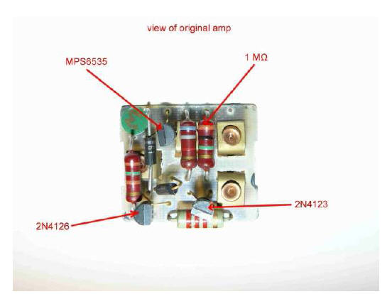 SY1 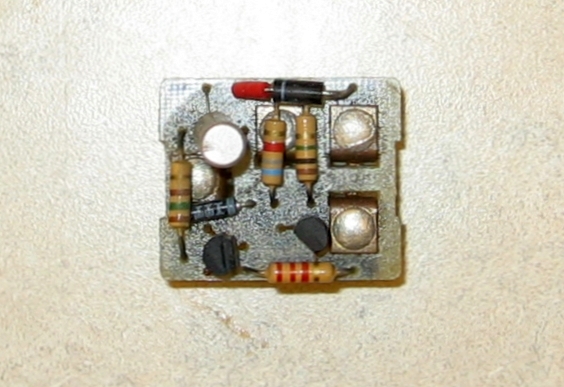 The interesting thing is the resister values are the same in both units however the transistors are different - OC204, 2N4123 and 2N4125. If the schematics turn out to be basically the same I will be able to use the new transistors specified in your document, with the 22M bias resister replacing the 1M resister. I just need to make sure first. Geoff | ||||
Jeff Young Prolific User Username: jeyjey Post Number: 225 Registered: 10-2010 |
The 2N4123 is the NPN sensor transistor; if you use a BC107 there then you won't have to change the resistor. The other two are the PNP amplifier transistors, and nearly anything will work there. I used a pair of BC327s. I also replaced the two diodes (as one of them had failed on mine). 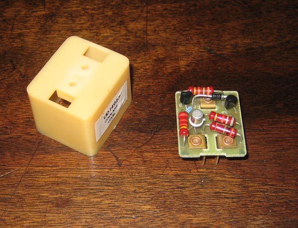 Cheers, Jeff. | ||||
Geoff Wootton Grand Master Username: dounraey Post Number: 945 Registered: 5-2012 |
Hi Jeff Many thanks for putting up the pic of your amplifier. I still can't figure out why my amp is so different. If you look at the resister nearest to us in your photo you can see the hole where it enters the pcb is occupied by a diode on my amp, pictured one up. In the pic from Brian's document, this hole is unused, however it looks like the resister on that pcb picks up the same track a little further along. I'm sure all will make sense when I have got time to look in more detail. Thanks for the advice on transistors. Geoff | ||||
John Kilkenny Prolific User Username: john_kilkenny Post Number: 223 Registered: 6-2005 |
Geoff, Tee One Topics Issue 36 P. 526 has the circuit for the SS1 Coolant Amplifier. It may be relevant. John | ||||
Geoff Wootton Grand Master Username: dounraey Post Number: 946 Registered: 5-2012 |
Thanks John. I had seen it, as mentioned in my third entry, above. I will be referring to it. Geoff | ||||
Jeff Young Prolific User Username: jeyjey Post Number: 226 Registered: 10-2010 |
> I still can't figure out why my amp is so different.... I expect, for instance, that all four holes on the top are connected to the same trace, and so they're interchangeable. Same with some of the other holes. Still, that would mean whoever soldered the board up actually knew what they were doing (ie: understood the circuit). That seems pretty far-fetched today, but perhaps it was more often true in the early days of electronics? Cheers, Jeff. | ||||
Brian Vogel Grand Master Username: guyslp Post Number: 1640 Registered: 6-2009 |
Geoff, The BD136/138/140 are all PNP transistors and the BD135/137/139 are all NPN transistors. I'm attaching the data sheets. I believe I still have extras of all of these, and I know I have additional rectifier diodes but am not sure about the Zener/breakdown diode. If you would be interested in having any of these for your rebuild let me know and I'll go through my "sewing box of electronic parts" to see what I have left and I can send them along. Brian
|