| Author | Message | ||
Brian Vogel Grand Master Username: guyslp Post Number: 1199 Registered: 6-2009 |
Since I had already taken the securing bolts off of the ballast resistor I decided it would be a good time to extract the thing to document it. There have apparently been a number of variants of the Lucas 9BR, and the best documentation I've found so far is on the Reopus Ignition webpage dedicated to the ballast resistor block, since the 9BR is really not "just a resistor." Here's what came off of SRH33576: 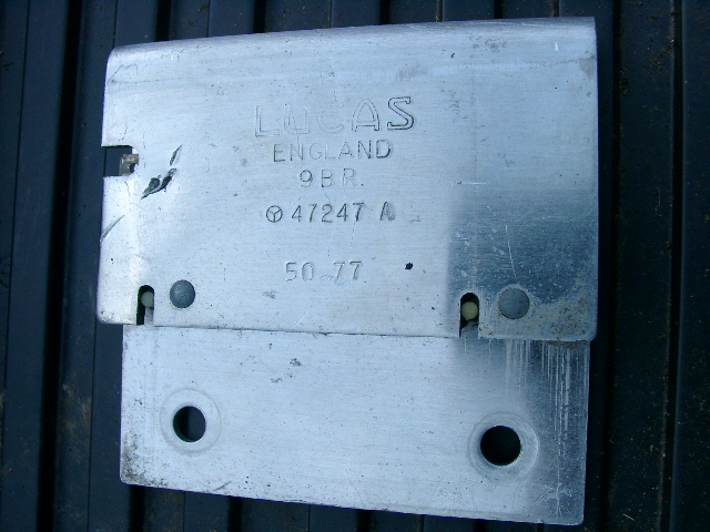 Of course, this variant is not documented on the Reopus webpage, so if anyone knows what its wiring diagram is, or where to find it, that would be helpful. This is a "quick and dirty" wiring diagram based on what I can actually see. The color of the wires on the input connector are impossible to see given its location (and I haven't consulted the real wiring diagrams): 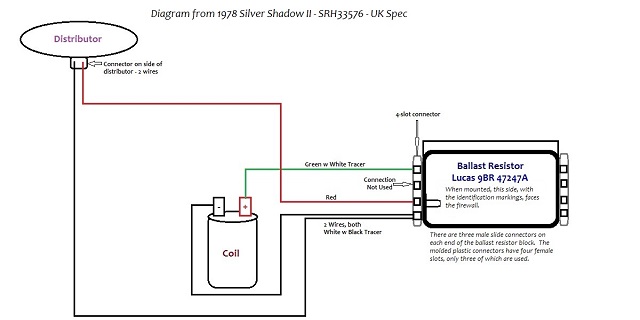 From what I've been able to gather the SY series cars started off with a conventional ballast resistor in a ceramic holder and eventually transitioned to the resistor blocks, but I have no idea when that transition took place. Perhaps this thread will turn into a tidy repository of all things ballast resistor related. Brian | ||
Bob Reynolds Prolific User Username: bobreynolds Post Number: 230 Registered: 8-2012 |
I would imagine the transition took place when the Opus electronic ignition was introduced. A conventional points system only needs a simple resistor with two leads. I don't know why your resistor has three leads. Evidently, it must be a bit more than a simple resistor, to work with the Opus ignition. Electronic ignition systems geerally do not use a ballast resistor at all. My 1975 Shadow is just a few weeks short of being fitted with the Opus ignition, and that is fitted with the conventional ceramic resistor block. | ||
David Lacey Experienced User Username: dlacey Post Number: 38 Registered: 11-2010 |
All, This OPUS/9BR ballast system was used on all the V12 jags where it has a reputation for cooking itself. More info here: http://www.jagweb.com/aj6eng/ignition.php It also was the ignition of the Ford DFV V8 F1 engine, so cannot be all bad. For a sort period the Ballast can be diagnosed/eliminated by running 12V direct to coil. On my Jag V12 I have fixed a failed resistor with an inline resister soldered into the relevant wire (tacho in my case). The three connections on the other side of the ballast are Tacho, Ignition+ and Start, top to bottom. Here's the jag schematic for reference: http://www.reopus.co.uk/Original%20Wiring%20XJ12.html I think we are approaching the time where we need to persuade Dave Curry at ReOpus NZ to create a version for the RR installation. | ||
Brian Vogel Grand Master Username: guyslp Post Number: 1200 Registered: 6-2009 |
David, I have been in contact with Dave Curry about precisely this. Initially he seemed to be very interested in doing so. After sending him some photos of the arrangement of the Opus ignition in the distributors from my cars he replied, "I had a brief look at some images of the V8 Rolls Royce and I decided that there the market would not justify the investment and time to manufacture a replacement." He also said, "123 make a replacement distributor for the Rolls Royce V8. Limora in Europe have them available the contact details are on my website." I knew about the 123ignition option, which is quite sophisticated. They also have an outlet in the USA. Brian | ||
John Kilkenny Prolific User Username: john_kilkenny Post Number: 181 Registered: 6-2005 |
Here is a circuit diagram for the Shadow 2 ballast arrangement. Under normal running the voltage to the coil and Opus Control Unit is reduced to the required voltage by the ballast resistor network. Because the input from the start relay is open circuit the connected resistor has no effect. However during cranking the Start Relay provides battery voltage via the resistor which boosts the voltage to the coil and control unit to make up for the drop in battery voltage caused by the high current requirement of the starter motor. 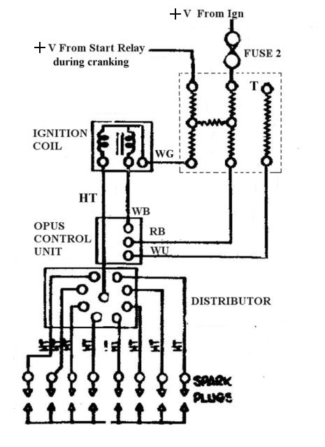 | ||
Brian Vogel Grand Master Username: guyslp Post Number: 1202 Registered: 6-2009 |
John, Where did that come from? I ask because it doesn't match what's in either of my cars as far as the number of wires going in to the distributor (which contains the Opus control unit). There are only two wires on both, the red w blue tracer (I'd missed that tracer under dirt) and a white with black tracer. There is nothing coming from the coil to the distributor other than the main HT lead. The ballast resistor network shown in that diagram (unless I'm misreading it)shows 6 resistors, and no other documented six-wire version of the 9BR has more than 4. Most peculiar. Brian, who's still curious as to what the values and connection arrangements are within the 47247A version of the 9BR | ||
John Kilkenny Prolific User Username: john_kilkenny Post Number: 182 Registered: 6-2005 |
Brian, My early Shadow 1 does not have anything as esoteric as ballast resistors or electronic ignition so I looked up the Shadow 2 Wiring Diagrams in rrtechnical.info/004/TSD4200/Chapter V Wiring Diagrams/Page 11. However looking further I notice that there is more than one version of the circuit. The circuit on Page 50 is simpler and doesn't boost the Control Unit voltage. This is likely the one on your car. The theory is the same. John | ||
John Kilkenny Prolific User Username: john_kilkenny Post Number: 183 Registered: 6-2005 |
Brian, Oops ! My last msg should have said Page 47 for the simpler version. John | ||
John Kilkenny Prolific User Username: john_kilkenny Post Number: 184 Registered: 6-2005 |
Brian, Refer to http://www.reopusignition.com/tests/the-ballast-resistor-block.html and also http://www.reopusignition.com/the-lucas-opus-wiring-diagram.html for a description of the Lucas ballast resistor function. The RR wiring diagrams are confusing. | ||
Brian Vogel Grand Master Username: guyslp Post Number: 1203 Registered: 6-2009 |
John, Thanks for the follow-ups. I will note, though, that I posted the link to the Reopus Ingnition Ballast Resistor Block page in the opening post of this thread. I've also been in direct contact with Dave Curry and he has no idea of what the arrangement of the 47247A variant of the 9BR is. Based on Chris Browne's photograph on the Christmas FTP thread there's also a B variant. Heaven only knows what the two numbers beneath represent. There is no way that those could be dates (or at least no way that makes conventional sense) since the "34 86" on Chris's would place it either before it existed or long after it was installed. I agree that the RR diagram you posted is confusing (but that's no criticism of you). It also bears only a passing resemblance to the actual arrangement in both my cars. Brian | ||
Chris Browne Prolific User Username: chrisb Post Number: 187 Registered: 2-2010 |
Brian, Having looked at several ballast resistors taken off various Shadows, I am fairly certain that the two numbers you refer to are, indeed, dates of manufacture - week 34 of 1986 as the numbers format on older units seem to bear this out. I can only assume that the one I posted a photo of is from a 1986 or later model car, clearly not fitted on a Shadow or Shadow 2 originally. Kind regards, Chris | ||
Brian Vogel Grand Master Username: guyslp Post Number: 1204 Registered: 6-2009 |
Chris, Thanks for the update. I had made the presumption that the one you posted the picture of had been removed from a Shadow II. Since these things seem to fail very rarely on our cars those numbers threw me if the thing was original and pulled from a Shadow II. Brian | ||
Brian Vogel Grand Master Username: guyslp Post Number: 1382 Registered: 6-2009 |
I'm reviving this thread in hopes that someday soon I will get back to getting everything back into shape on both SRH33576 and LRK37110 as far as ignition goes. The following is a diagram of the Lucas 9BR 47257A ballast resistor taken from a screenshot of the ReOpus page mentioned by John Kilkenny: 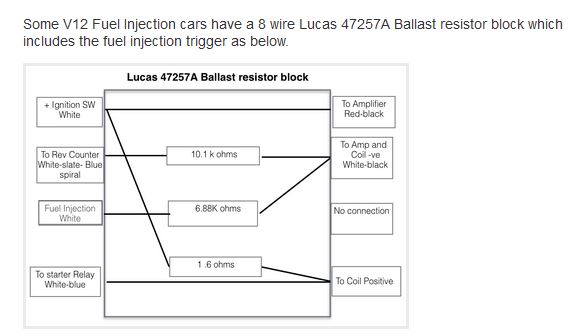 based upon what I'm seeing on the 47247A version of the 9BR that's on SRH33576, I suspect it's pretty much identical to the 47257A version except that the 6.88K Ohm resistor is omitted from the block and the C and G connector positions are unused because of this. The diagram I put together for this doesn't read well if reduced to 640x480, so I've put it on Google Drive instead and here's the link: SRH33576 Wiring and Inferences based on ReOpus Diagram If anyone happens to have the wire colors documented for the incoming side of the 9BR (as opposed to the "to distributor" outgoing side) I'd love to know what those are. It's very difficult to get a good look at these wires on either of my cars. Also, if anyone happens to know whether my SWAG regarding the difference between the 47247A and 47257A is correct, or how it's incorrect, please share. Brian, who's going to have to figure out how to wire the Mallory distributor for SRH33576 when work commences again | ||
Robert Noel Reddington Prolific User Username: bob_uk Post Number: 104 Registered: 5-2015 |
Ballast resistors through the years. Sounds like a school educational film. John Kilkennys wiring diagram if correct. Would make diy manufacture relatively easy. A guessimate for the coil resistor is 2 ohms. For the amplifer , amp consumption needs to measured and then the ohms can be calculated. The circuit shown is a voltage divider. There is an online calculator program that does the calculations for you. Resistors can be made from electric heater coils wire. This is similar to the heater blower motor resistors on my shadow 1 | ||
Brian Vogel Grand Master Username: guyslp Post Number: 1679 Registered: 6-2009 |
Now I'm giving this thread another bump secondary to additional research triggered by private correspondence with a regular on these forums. Before I continue, when I talk about the right versus left side of the ballast resistor block it assumes that you are looking at it oriented in the same way that it is in the photo-diagram hybrid, with the lettering facing you such that it is oriented correctly for reading. When this thing is mounted in the car the "fold" on the housing is facing the ground and the lettering is upside down facing the firewall. Here is a diagram I put together based upon the ballast resistor block that I found on SRH33576 and information at the ReOpus site: 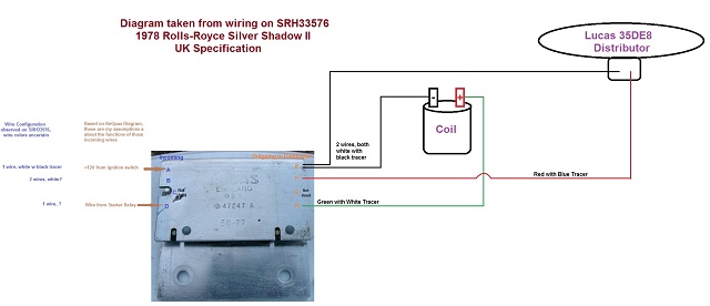 Note: A far more readable version of this diagram can be downloaded from my Google Drive here. I reduced it to fit the forums for inclusion in this post and it doesn't read well at all. What's interesting is that the ballast resistor block on SRH33576 has but one cut out for the plastic connector guide, on its unlettered side: 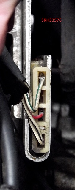 The photo used in the diagram I posted first clearly shows that the right side of the ballast resistor block has no cut-out on its lettered side on the right. This is in contrast to the same side of the ballast resistor block in LRK37110, which has two separate cut-out channels, one on the lettered side and one on the unlettered side on the right end of the case: 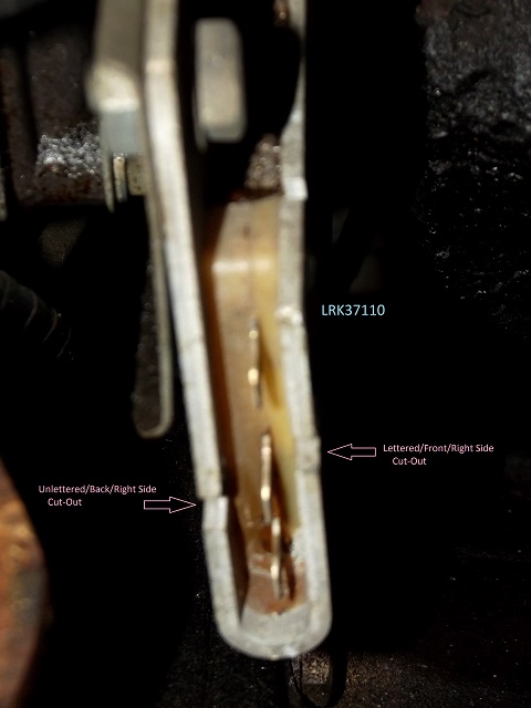 I have not removed the ballast resistor on LRK37110 and don't intend to do so, so I do not have the full Lucas part number for it. I can say that what I can see (and feel, the lettering can be felt) of it the configuration of the case is very similar except for this extra cut-out channel. I don't know what's on the left side as far as cut-out channels go on the unit on LRK37110. You can see that the one on SRH33576 has a single channel on the lettered side on the left side of the housing. When the distributor is plugged in on LRK37110 it would appear that the wiring would follow the same layout as it does on the outgoing side of the ballast resistor block on SRH33576. I wonder what the deal is with that second cut-out channel on the opposite side of the housing? Brian | ||
Brian Vogel Grand Master Username: guyslp Post Number: 2114 Registered: 6-2009 |
Gentlemen, I'm reviving this thread because I have at least some hope that I might resume work on LRK37110 either over the winter or come spring as far as getting a replacement distributor installed. I'd also like to know more about exactly what comes or goes where and does what wiring wise with the ballast resistor block connections in the SY2 series cars. Here is a reworked, annotated photograph of the ballast resistor block from SRH33576 with the annotations based upon a ballast resistor block diagram kindly supplied to me when this topic was last active: 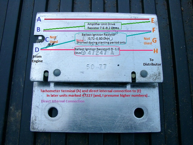 Each side of the sides has a 4-position plastic connector with male slide connectors contained in three of the four slots, with the slots for positions C and G vacant in their respective connectors. On the side going to the distributor: Position E: Two wires, white with black tracer, one going to the coil negative terminal and the other going to the distributor. Since these two wires meet there it is also a direct connection between coil negative and the distributor. Position F: One wire, red w blue tracer, to the distributor. Given the layout of the resistor block I am presuming when the key is in the start position a full +12V is being sent to the distributor [via Pos B] but once released to the run position the power comes through the resistor that connects Pos D to Pos F. Position H: One wire, green with white tracer. Feed through second ballast ignition resistor (0.9-1.0 ohm) to coil positive, routed via the starter relay while the key remains in the run position. On the side coming in to the ballast resistor block: This is the bit that's more of a mystery to me, in particular, where the wire from Position A goes. It is very hard to get a good fix on the wire colors when the block is mounted in situ and I can't find a decent diagram that I can fathom. I'm not making the connection between the diagram Mr. Kilkenny and am having more than a bit of difficulty trying to read the one on PDF page 47 of chapter V given its size and resolution. It also appears to have nothing shown for what is position A as far as any wire being joined to it. Position A: One wire, believe white with black tracer. Origin or Destination and purpose unknown. Position B: 2 wires, possibly white. One has to be the +12V from the ignition switch when it's in the start position, but what's the other? Position D: +12V source from the starter relay I could be completely, entirely off with regards to the wiring on this side. After I have this settled in my mind I will have a better idea of exactly where the three leads for the Mallory replacement unit need to be connected. One is ground/earth, so that's a simple matter of finding a convenient location on the chassis. Brian P.S. This is the source I used in making the annotations to the above photograph: 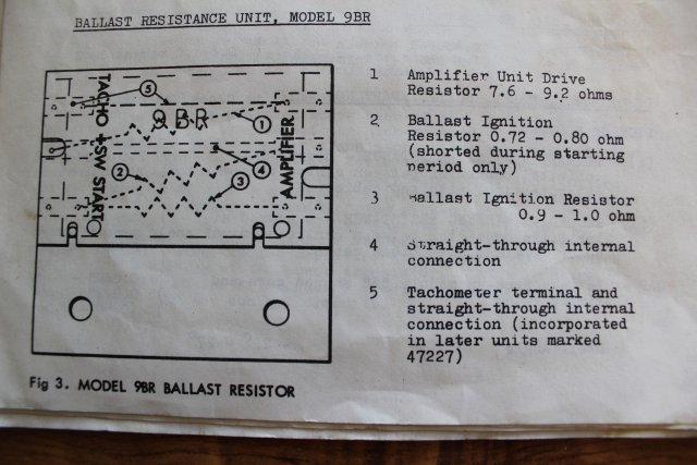 | ||
ross kowalski Prolific User Username: cdfpw Post Number: 283 Registered: 11-2015 |
I was idling the car for 30 minutes this afternoon, after moving it to clean leaves from under it. I got in to drive it back up the driveway and it stalled.??? That's a new trick.. I popped the hood and the checked the coil for spark, no spark. Hmmm. I touched the coil and ouch way hot. I hosed the coil down with r134 and checked the spark, good spark. Put the coil lead back in the dizzy and it started immediately. I backed up the driveway and checked the voltage at the coil, 13.45 which is the charging voltage. I turned the car off and checked the two wires at the coil one was cranking voltage and the other full battery voltage with key on. I then checked the coil and got 3.6 ohms on the primary and something reasonable (6k? I forget) on the secondary. I checked the manual and it lists a ballast resistance in the circuit. I did have some trouble finding the correct diagram as I didn't know what diagram covered srh 8844 So. 1. Is there supposed to be a ballast resistor on a 1970 Shadow? 2. If there is, where is it located? 3. How many ohms is a 1970 shadow coil supposed to have on the primaries?. | ||
Geoff Wootton Grand Master Username: dounraey Post Number: 1618 Registered: 5-2012 |
Hi Ross If your car is 6.75 liter with single points then yes, your car should have a ballast resister. It is bolted to the bracket that holds the coil. The first picture is a top view of the distributor and coil. The ballast resister is buried beneath that lot. 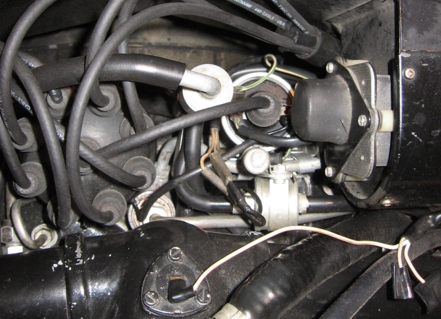 The second picture is a detail of the coil bracket with the red arrow pointing at the ballast resister. 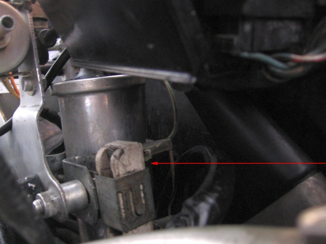 Geoff | ||
Geoff Wootton Grand Master Username: dounraey Post Number: 1619 Registered: 5-2012 |
if your coil is really hot, you may have the dwell angle too great. The best way to access the ballast resister is to pull the distributor out and work from the side. | ||
ross kowalski Prolific User Username: cdfpw Post Number: 284 Registered: 11-2015 |
Geoff, Thanks that's perfect and perfectly clear pictures. The dwell angle should be OK, as I set it with a dwell meter and the little screw on the dizzy, but maybe it vibrated out. Ill check the point gap tomorrow. Mine never came with a ballast resistor so I must have been cooking my coil to beat hell all this time! I just assumed it had one and it was working. I think I might swap the coil. I have a few around and I think mine must be tired. Thanks again. | ||
ross kowalski Prolific User Username: cdfpw Post Number: 285 Registered: 11-2015 |
Geoff, Looking at your picture, it looks like a wire comes into the too of the ballast resistor and slits off to power the coil, the bottom of the ballast resistor is connected to ground I assume? Thanks. | ||
Geoff Wootton Grand Master Username: dounraey Post Number: 1620 Registered: 5-2012 |
Hi Ross The connector on the bottom end of the ballast resister (out of shot) goes to the 12v supply. In normal running this supply goes through the ballast resister and delivers 9v to the coil through the green and white wire. The other wire on this connector (shown in the photo) goes to the starter relay. When you crank the engine the ballast resister is bypassed by this wire to deliver 12v directly to the coil to get the engine started. When the starter relay goes off, the coil voltage reverts back to 9v through the ballast resister. As a point of interest, I have been running my car for the past year without a ballast resister, through a 12v coil. I thought I'd destroy the points but everything has worked fine. A while ago John Kilkenny, who is an expert on these things confirmed my setup should be ok. Geoff | ||
richard george yeaman Grand Master Username: richyrich Post Number: 707 Registered: 4-2012 |
Several people on this forum myself included, fitted electronic systems inside the distributor fitted a 12 volt coil and threw the ballast resistor in the bin, made a big difference to SRH19529. Richard. | ||
ross kowalski Prolific User Username: cdfpw Post Number: 286 Registered: 11-2015 |
I think someone did that conversion on my car already. Here's a diagram of what is installed.  My coil measured out at 3.5 ohms so it should not overheat with 12v. The wire that the PO attached from the starter relay to supply crank 12v voltage no longer does anything so I pulled that and taped it. I think my coil is just bad. No spark hot, spark cold on a coil usually means new coil time. My battey is a pretty sad as well, I just put it on the load tester and it dropped to 10v on a 100A load, not good. I guess I have to add coil and battery to the list. | ||
ross kowalski Prolific User Username: cdfpw Post Number: 287 Registered: 11-2015 |
Richard, I might eventually go this route. I like the fact that pertroinx (and clones) don't use condensers which are notoriously poorly made these days. I'll probably add that to the list. | ||
ross kowalski Prolific User Username: cdfpw Post Number: 288 Registered: 11-2015 |
Geoff, It's possible I am running too much dwell. I just looked up the spec and it is 25 degrees. I might have set it to the "normal" 35 degrees for an eight. Wonder why it's 25 degrees? I'll pull out the dwell meter later and see. | ||
ross kowalski Prolific User Username: cdfpw Post Number: 289 Registered: 11-2015 |
It was the coil. Turns out the dwell was spot on. I must have looked up the reading. https://www.youtube.com/watch?v=BTQ3hvWmFOc I ran the car to operating temperature shut it off and checked the coil and it was reading 2.6 ohms and the coil was hot. I had two coils to chose from in the 3.5 ohm range, International Harvester and another Lucas so I went with Lucas. The new coil seemed to do the trick. https://www.youtube.com/watch?v=N5E3ezEVGzM I ran it up to temp and the coil stayed cool. I'll have to wait until spring and driving weather to find out if things are really OK. Being under the hood I noticed some PO had used a scotch connector. I'll find out what that was intended to fix tomorrow and fix it properly.  | ||
Geoff Wootton Grand Master Username: dounraey Post Number: 1627 Registered: 5-2012 |
Nice one Ross. Good to see it's sorted. The dwell angle was really steady as you rev'ed the engine - a good sign. | ||
John Kilkenny Prolific User Username: john_kilkenny Post Number: 260 Registered: 6-2005 |
The early Shadows did not use a ballast resistor. The starter motor was a Lucas M45G with an initial lock torque of 18.8 foot pound with 430 amps, and at 1000 rpm cranking speed a torque of 6.7 foot pound with 220 amps at a battery voltage of 9.75. This reduced voltage was applied to the coil when cranking but apparently was high enough to start the motor OK. On later cars the starter motor's power was increased to provide a lock torque of 28 foot pound with 825 amps and a 1000 rpm cranking torque of 14 foot pound with 525 amps. This would further reduce the coil voltage when cranking and presumably led to the introduction of the ballast resistor. Initially the ballast resistor was a single component but with the introduction of the Opus system resistors were added to control the Opus circuitry. The dwell angle is the number of degrees that the points are closed. For an eight cylinder car there are 45 degrees available for each cylinder and the dwell angle needs to be long enough to properly charge the coil. For a Shadow with a points distributor this is around 30 degrees and is not critical. For my Shadow 1 the spec is 31 to 37 degrees with a 0.015 inch gap. It is not likely that Ross's hot coil is due to a high dwell angle. It may be that the coil is faulty and needs to be replaced. On the other hand if the ballast resistor has been by-passed and the original low resistance coil is still in place this could cause it to overheat. It should be replaced with the 12 volt version. | ||
richard george yeaman Grand Master Username: richyrich Post Number: 708 Registered: 4-2012 |
Ross last year or the year before I relocated my coil to the inner guard/fender because it is a much cooler place rather than being cooked in the hottest place in the engine compartment, and also more easy to check or replace. Richard. | ||
ross kowalski Prolific User Username: cdfpw Post Number: 292 Registered: 11-2015 |
Richard, You are right about the coil location. I'll have to look for a good place to put mine. I don't really like the idea of a long primary wire, but I certainly do like the idea of putting the coil somewhere lower, accessible, and away from the engine heat. As you might have guessed, I am not a purist when it comes to such matters. | ||
ross kowalski Prolific User Username: cdfpw Post Number: 293 Registered: 11-2015 |
John, Thanks for the starter info. I have been looking at fitting a geared starter for some time now and that makes me even more inclined to do so. I was looking at the Technical manual wiring diagrams. It is difficult to find my car SRH 8844 but what I think covers my car shows one and the section called "cars built to 1973 electrical spec" seems to show one as well. I have a 3.5 coil in there now so I'm not going to be adding a resistor. Resistorless it is. 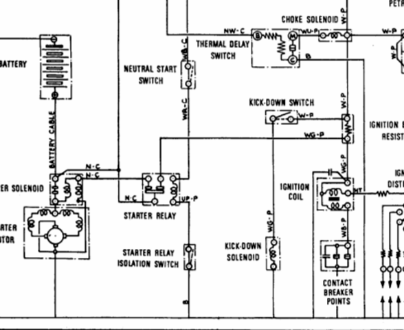 The dwell thing sort of makes sense as the engine is not a revver. Dwell is not just a degree, but an actual time amount, the time shortens as you spin the engine faster. This is a Royce engine so it won't be doing any undignified fast spinning. I guess I am just used to 35 for 8's. | ||
Patrick Lockyer. Grand Master Username: pat_lockyer Post Number: 1110 Registered: 9-2004 |
Hi Ross to fine tune your question. [1. Is there supposed to be a ballast resistor on a 1970 Shadow? 2. If there is, where is it located? 3. How many ohms is a 1970 shadow coil supposed to have on the primaries?.] 1. On the 1970 Shadow no ballast fitted. 3.The coil primary should be 4.25-4.65 ohms. The secondary should be 5500-7100. The Shadows from 65-69 were the same however the 70 Shadow had the dwell changed from 31-37 to 26-28 degrees. 1971 Shadows onwards all had a ballast of 1.3-1.5 ohms until later cars with the Opus ignition. Timing after dwell at 3 degrees btdc then fine tune to the type of octane fuel. Nice steady dwell on your car, hate those scotch connectors. | ||
Geoff Wootton Grand Master Username: dounraey Post Number: 1628 Registered: 5-2012 |
Hi Ross Re: I checked the manual and it lists a ballast resistance in the circuit. I did have some trouble finding the correct diagram as I didn't know what diagram covered srh 8844 The Technical Library has the wiring diagrams for your car. They are included in the Silver Shadow, Bentley T and derivatives workshop manual section. http://rrtechnical.info/sy/tsd2476/tsd2476.htm You will find the wiring diagrams for left hand drive cars from serial number 6000 to 9000 in the wiring diagrams Part 1 section. Geoff | ||
David Gore Moderator Username: david_gore Post Number: 2446 Registered: 4-2003 |
Geoff and Ross, The high resolution version of TSD2476 in the Technical Library is essential for viewing the fine detail in the wiring diagrams as the relevant sections can be enlarged sufficiently to reveal wire colours and connections. http://rrtechnical.info/sy/tsd2476/tsd2476hires.htm . | ||
ross kowalski Prolific User Username: cdfpw Post Number: 295 Registered: 11-2015 |
Geoff and David, I was using the technical library scans, but it seemed everything was for LHD cars or the wrong serial #. I might fit a ballast resistor to bring the 3.5ohms of the circuit to 4.xohms but 3.5 is a pretty standard resistance for unballasted circuits so maybe not. It would drop the current about 25% from 4 to 3 amps. Patrick, Hear hear on the scotch connectors. What a hack job those are. When people use them, what they really should be using is Wago 221's (prounonced Va go) Wago's cost like 25 cents.  And really, what they SHOULD be doing in fixing the problem with the harness and not piggybacking a lead across a defect in the first place. | ||
Patrick Lockyer. Grand Master Username: pat_lockyer Post Number: 1111 Registered: 9-2004 |
Hi Ross, If you go down the fitting of a later Shadow 1.4 ohm ballast then the coil primary will be 1.43-1.56 ohms The coil secondary will be 4500 ohms. Dwell 31-37. Have not seen the wago connectors thanks for that. | ||
John Beech Prolific User Username: jbeech Post Number: 209 Registered: 10-2016 |
John K, Tootsie (my 1969 Silver Shadow - SRX6816) does have a ballast resistor. Tootsie is a left hand drive car and the resistor is mounted on the driver's side of the engine (on the cylinder head). While it's a bit close to the firewall it's just a short hop from there to the coil. Anyway, thanks for the specs and background info regarding starters and other details - good one mate! Geoff, thanks for the link to the hi-rez version of the manuals. Brian V. had previously told me about these and I had forgotten. Anyway, I already downloaded the manuals and had them printed (and spiral bound into about 6 volumes for ease of use). Now I am going to print (in large scale) both the wiring and hydraulic diagrams. Then I'll have them laminated so I may pin them to a convenient wall for ready access/inspection. Good tip. | ||
Patrick Lockyer. Grand Master Username: pat_lockyer Post Number: 1112 Registered: 9-2004 |
Hi John, yes the data I gave was for rhd cars as is the car of Ross's in the USA. Out of interest at the end of the pages of UK RR specs they list a car 1971-72 as D81 mk 70A 8 cylinder 6156cc. A British car due to Lucas fittings maybe? but no name! |