| Author | Message | ||
Michael Moran Experienced User Username: mjcmoran Post Number: 25 Registered: 8-2005 |
Just a very simple, perhaps even simple-minded question that Tee One Topics does not actually mention in the detailed description of header tank refurbishment or the Shadow Workshop Manual. In replacing the steam valve in the header tank I assume the wider base section sits on the rubber seal at the bottom of the opening. When I removed the cover plate it seemed to me the valve had been installed upside down by someone as the narrower top was sitting not very comfortably on the rubber seal, the whole valve wobbling about. So which position is correct? Michael Silver Shadow SRH 18723  | ||
Chris Browne Prolific User Username: chrisb Post Number: 135 Registered: 2-2010 |
Hello Michael, You are correct. The widest end fits at the bottom against the seal. Also make sure that the outlet hole on the side of the steam valve faces the overflow hose. I know this because my car had been meddled with in exactly the same way i.e. the stem valve had been fitted upside down. Kind regards, Chris | ||
Michael Moran Experienced User Username: mjcmoran Post Number: 26 Registered: 8-2005 |
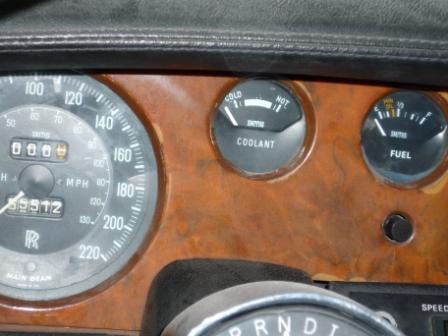
Thanks Chris - I actually observed both these instructions some time ago but was just double checking. Common sense I would have thought if you were a mechanic. On the Shadow I the fact there is no indication of engine temperature and possible overheating (as age creeps on and channels silt up) is real 'nerve wracker'. The cylinder head overheat warning buzzer only comes on (if it does) rather too late in the day. I have replaced mine recently when going through a preventative service checklist for any possible overheating in the future. The silent killer. Checking flow in the radiator core, new hoses, thermostat, steam valve and so on. Just in case. However you can never know exactly what temperature the engine is operating at unless you install with some great difficulty a gauge somewhere in the cabin (but where and how is a big question). I know about this option but have never gone down that road and continue to live in a state of mild tension on long motorway trips in summer. Mike | ||
Omar M. Shams Grand Master Username: omar Post Number: 407 Registered: 4-2009 |
Why endure all this pain and suffering Michael? How useful is your ammeter? Will its loss ever cause you any grief or expense? the answer is NO. Just ditch the ammeter and put a temperature gauge in its place. An engine replacement is the kiss of death for these cars - don't set yourself up for that. | ||
Michael Moran Experienced User Username: mjcmoran Post Number: 27 Registered: 8-2005 |
Thanks Omar The checks and replacements have all been done now and I have no problems of overheating I can notice visually at all. I think it is a good idea to check the cooling system carefully every now and then anyway. I try to do sensible preventative maintenance on the car despite the cost. The installation of an accurate temperature gauge (not the unfortunate unreliable type first installed in Shadows) and of a proper size and dial style in place of the ammeter is a big deal to source and install. I did go into this in detail a while ago. I would not dream of approaching such a project in PL for all the reasons in my other recent thread on flanges. When I go to Berlin later in the year I will ask the RR engineers there about this idea. Mike P.S. If you have done it easily and attractively to deal with the extreme heat of your location I would be pleased to know the details and have a picture of the result. Summer is very short in Poland after all! | ||
Omar M. Shams Grand Master Username: omar Post Number: 408 Registered: 4-2009 |
Dear Mike, go to http://au.rrforums.net/cgi-bin/forum/show.pl?17/15761 and you will see the photo of my installation. Thanks Omar | ||
Brian Vogel Grand Master Username: guyslp Post Number: 871 Registered: 6-2009 |
Omar, You somehow pasted the wrong link and it circles back to this thread. Is this post in the thread entitled, SRH18295 Overheating, the one you had in mind? You cannot "trust" the URL that shows in the address bar when you're reading to be the correct one, which I've learned the hard way. The easiest way to snag the URL you really want is to do a search then snagging the URL by right-clicking on a keyword that's underlined in whichever one of the "synopsis lines" under the returned thread title that takes you to the post you want. Brian | ||
Geoff Wootton Grand Master Username: dounraey Post Number: 434 Registered: 5-2012 |
Hello Omar I could not get your link to work. This a project I intend to carry out on my SY1 as soon as I am re-united with my car (currently stored in Las Vegas whilst I am in Cleveland). My initial thoughts were to use one of the small diameter gauges and fit it in the position currently occupied by the radio balance switch, which is redundant on my car. 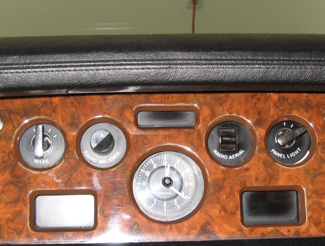 Can you remember where you fitted the temperature sender unit on your car? Regards Geoff. | ||
Geoff Wootton Grand Master Username: dounraey Post Number: 435 Registered: 5-2012 |
Hello Brian Thanks for that. This must be the thread Omar intended to point to. Geoff | ||
Omar M. Shams Grand Master Username: omar Post Number: 410 Registered: 4-2009 |
Sorry for the confusion. I can find the thread when I do a search but the address does not change after it finds the thread. That's why I copied the wrong link. Sorry about that. The thread is on this forum and it is called: SRH18295 Overheating. Thanks | ||
Omar M. Shams Grand Master Username: omar Post Number: 411 Registered: 4-2009 |
 | ||
Omar M. Shams Grand Master Username: omar Post Number: 412 Registered: 4-2009 |
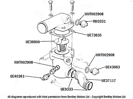
She sender unit is an easy modification. Just buy a thermostat housing form a scrap Shadow II and it will have the sensor already embedded in it. | ||
Geoff Wootton Grand Master Username: dounraey Post Number: 436 Registered: 5-2012 |
Many thanks Omar Geoff | ||
Bob uk Unregistered guest Posted From: 94.197.122.81 |
Somewhere around the thermostat housing are blanking plugs some go to inlet manifold some go to Water jacket obvious because water comes out Screw sensor in hole For gauge try BL MINI These had smith's gauges One side goes to fuel gauge feed voltage stabiliser side over side goes to sensor use mini sensor A brass adaptor maybe necessary My gauge is made by Tim but I reckon the Smith's is what RR would have fitted The 2 wires from the.ammeter are best joined and insulated The instrument light will fit like a proper factory job The correct colour for the wire is green with black overcover Don't use those nasty blue connectors use soldered brass type with clear plastic flexible cover To give a factory look I think the amp meter is of far less use at keeping cooked engine paranoia at bay which any sensible driver should have I ain't happy unless I can glance at a gauge Also I check the heater hot air means hot Water and hot Water means system has water (Message approved by david_gore) | ||
Bob Reynolds Prolific User Username: bobreynolds Post Number: 103 Registered: 8-2012 |
"A brass adaptor may be necessary" There lies the problem! Where do we get the adaptor from? | ||
Michael Moran Experienced User Username: mjcmoran Post Number: 28 Registered: 8-2005 |
Omar Someone I discussed this with told me the main difficulty for him was finding a place to thread the wires through the bulkhead from the thermostat to the gauge. How did you do this? Mike | ||
Paul Yorke Grand Master Username: paul_yorke Post Number: 1214 Registered: 6-2006 |
Remember a shadow 1 gauge uses a green top sender. The bulk head to cabin plugs under the heater blower motors usually have an empty terminal or two. If you can't find the correct terminals use an uninsulated female. Drilling holes often leads to water ingress.  | ||
Bob Reynolds Prolific User Username: bobreynolds Post Number: 104 Registered: 8-2012 |
You can easily pass many wires through the unused hole for the wiper rack tube. The bulkhead has holes for LHD and RHD wiper racks to pass through, but only one is used. The unused one will be right behind the dashboard where you need it. It might have a blanking plug in it - just make a hole in the rubber plug. You will need to temporarily remove the scuttle filter to thread the wires through from the bulkhead to the dashboard, as the two holes are not quite in line with each other. | ||
Omar M. Shams Grand Master Username: omar Post Number: 413 Registered: 4-2009 |
Dear Mike and Bob, The two Bobs have hit the nail on the head. There are many places to thread wires. If anything that should be the least of your worries. Getting the right gauge with the right look to make it look like it was factory installed is in my opinion the bigger challenge. Over the years I have snapped up every gauge I could find and I now have two spares. They do come up for sale from time to time on ebay - keep an eye out. Omar | ||
Omar M. Shams Grand Master Username: omar Post Number: 414 Registered: 4-2009 |
 | ||
Bob uk Unregistered guest Posted From: 94.197.122.75 |
Adaptor The plug will give outside thread To measure and identify a thread Imperial threads are threads per inch tip Metric are distance between creasts Using a micrometer measure the dia If you get a dia size that seems not to be nominal in metric or inch Then most likely it is British standard pipe BSP fine or course Once the thread is identified then a thread and pipe specialist will help or race car shop My Tim gauge cost �12 approx in 2005. This came with 5 adaptors The wire on my car goes through the floor with the fuel pump wires for the lpg conversion ( pump shut off) Dollop of silicon I fitted the temp and oil gauges when the car was lpged to monitor the engine just in case I removed the wood from where the 8 track went And put the gauges there with black leather surround This looks horrible looked ok at first I intend to put these gauges where fuel and amps go. Lpg only I don't use petrol The hole voided by the gauges will be an docking station for a mp3 player which has 5000 plus tracks 2 problems Oil level gauge and lpg gauge I always dip the engine The ply gauge could go in with docking station I would like the 4 gauge set up from a corniche but this requires major work and different wood Lots of money I will not chop my wood.around To wire the docking station I have a 4 channel 10 watt power amp which will fit under the ashtray This amp has no controls and looks like a aluminum hedgehog so the control is preset by fixed resistors and then the mp3 player controls are "in range" Simple but time consuming job Forgot The.suppliers of gauges have.adaptors so once you have the plug.size Note if the adaptor is BSP the size given is the inner dia of the pipe not the outside dia I'm other words the hole size of the pipe The specs are in engineers tables such as Zeus And last my radio balance control is now a switch for the fog lamp I did the writing with lectraset from art shop (Message approved by david_gore) | ||
Jeffrey McCarthy Grand Master Username: jefmac2003 Post Number: 433 Registered: 5-2007 |
Bob UK mentioned earlier that when replacing the Ammeter with a Coolant gauge "The 2 wires from the Ammeter are best joined and insulated". I've left mine unconnected but well insulated with electrical tape. Is there a reason for joining them apart from tidyness and being easier to tape up? Perhaps some feedback effect on the voltage regulator? Also the original Smiths gauges in the Shadows, unless RR ordered some specific modification from Smiths, were of the type that required 10 volts to work accurately - on Jaguars there was a small voltage regulator wired into the circuit before the gauges to make this happen. There are now even better than original 10v regulators made for this purpose. I wonder if installing one (they're about half the size of a matchbox) might make the Coolant gauge more accurate? The new "Smiths" reproduction gauges on the market are designed to run at 12 volts. They also come in the style to match the other Shadow gauges. Not that I trust mine all that much - it's really just there so I notice if something out of the ordinary starts to happen - and whenever that has, it's usually been a loose connection on the gauges circuit! I've fitted a "sudden loss of coolant alarm" which is probably more useful and generally advised by those with experience of Shadow coolant hoses invisibly deteriorating from the inside out until one day they just split. | ||
Bob Reynolds Prolific User Username: bobreynolds Post Number: 105 Registered: 8-2012 |
The Ammeter is shorted out by the Ammeter Shunt, which carries virtually all the current for the electrical circuits. However, it's not a complete short circuit, as some current is required to work the Ammeter. If there is no Ammeter in circuit, then you can put a full short circuit across the Ammeter wires, which will reduce the resistance of the supply to a minimum. Most cars of the era had a Gauge Voltage Stabiliser (looks like a flasher unit) to provide a stable voltage to work the gauges. The Shadow doesn't have one but I've no idea why. Could it be that the gauges are special ones which contain their own stabilisers? | ||
Randy Roberson Prolific User Username: wascator Post Number: 232 Registered: 5-2009 |
Hi, I found a gauge currently made by Smith's which has oil pressure on the top half and coolant temperature on the bottom half. Just so happens I see on the 'Net the instrument panel on a Phantom III and it shows almost the exact gauge. Might it be a good choice? | ||
Jeffrey McCarthy Grand Master Username: jefmac2003 Post Number: 434 Registered: 5-2007 |
Bob, Thanks for the info - I'll join the wires in the morning. Having taken several of these (broken) gauges to pieces. I've seen nothing that looks like an internal voltage stabiliser of the period: no resistors or condensers etc. Just the usual thin wire and a coil and a needle. I have 2 old fashioned stabilsers (one a new repro) but no idea of what the pin out arrangement is. There are 3 pins & presumably one is an earth and the other two are current in and current out? Searching the net hasn't yielded any enlightenment. | ||
Bob uk Unregistered guest Posted From: 94.197.122.80 |
The Tim gauges I have are internally regulated Bl MINI gauges have a external stabilizer Try mini spares site Other brit cars used this gauge Not Ford Millions of these were made There will be a site with these parts Google mini and there will a very long list The 3 pins might be input and 2 output one for each gauge on a typical temp and fuel gauge only I have a vague memory of an Austin 1100 dash These stabs where jusnot earthed Check with digy meter Bench test with hot Water and thermometer I love doing this sort of stuff on the Bench I show the.grand kids how it works Mid way 90c about right (Message approved by david_gore) |