| Author | Message | |||
Bill Vatter Experienced User Username: bill_vatter Post Number: 110 Registered: 09-2004 |
Has anyone tried raising compression ratio? How did you do that? How much increase did you get? What was the performance result? | |||
Jeff Martin Experienced User Username: jeff_r_1 Post Number: 69 Registered: 07-2018 |
Apparently some have shaved the head to get it up to 120 PSI, but then this decreases the area where the exhaust valve is and the burnt gasses won't evacuate properly causing a sporadic and somewhat lumpy idle. The engine wont' sit still at idle. Don't know how true that is though. I think I read that here somewhere on this forum. | |||
Bill Vatter Experienced User Username: bill_vatter Post Number: 112 Registered: 09-2004 |
I think that story is correct. The first attempt by RR to increase power output of the EPW six was to mill the head to raise compression ratio. The result was insignificant powerincrease but unwanted increase in engine roughness. That was the cause of raising displacement. I think it was years later they concluded the cause of the poor performance was "Shrouding arount the exhaust valve, made worse by the head milling. I am thinking the best way to raise compression is a domed piston combined with removing some metal from the head near the echaust valve. I seek to learn who might have done that mabz | |||
michael vass Frequent User Username: mikebentleyturbo2 Post Number: 677 Registered: 07-2015 |
Why not fit a turbo | |||
Jeff Martin Experienced User Username: jeff_r_1 Post Number: 70 Registered: 07-2018 |
Hey Bill A quote from Christopher Carnley from a post in another thread. "You cannot fit domed pistons or any with any lozenges on top. The inlet valve travel is quite considerable, and the piston almost strikes the face of the head. Compression was raised by slicing off a bit of the head face and fitting a thin corrugated gasket. This was also done to the S1 head to raise the compression. Your best bet is to scrap the exhaust system and fit two Jaguar boxes, if on twin pipes. The MK VI system absorbs 28 BHP and the fan another 5 Chesman Engineering make an S1 head that is up to 8.8:1 CR". http://au.rrforums.net/forum/messages/16999/12802.html?1592034711 From Friday June 12th I'm not sure how Chesman Engineering got around the exhaust valve problem, but maybe RR redesigned the S1 head that solved the "shrouding" problem. | |||
Bill Vatter Experienced User Username: bill_vatter Post Number: 113 Registered: 09-2004 |
Hi Jeff, Thanks for that Reference. That statement from Chris Carnley is incorrect, simply NOT true. Think about the motion of the piston and valve as the engine is running. As the intake valve opens, the piston is moving down the bore faster than the speed of the opening valve. When the intake valve is fully open, the piston is more than half way down the bore, and the valve closes long before the piston comes back up to the top. The closest they come to each other is when the piston is at TDC between exhaust and intake strokes, 360 degrees from ignition. At that point in time, the separation between piston and valve is considerable, about half an inch. If you were to fit a piston with a bump on top that extends into the combustion chamber, You would have what is common to more than half of modern automotive engines. These are referred to as "Interference engines," and this attribute does have some important consequences if the camshaft stops turning while the engine is running, which would happen if the timing belt were to fail. For an EPW RR six, it means you need to be aware when you take off the camshaft gear. With the gear removed, you cannot spin the engine without a problem unless you first remove the rocker arm assembly. The engine does need to be correctly timed, or at least close to correct before you put on the rocker arm assembly. This does not introduce problems as long as you are aware of the interference situation and work accordingly. No extra work, but you do need to pay attention to what you are doing. So what I am getting at with my question, has anyone done this, or milled to head a significant amount, and how did it run afterwards? I believe that if pistons with raised tops were used, you could significantly increase the compression ratio, and that would allow you to take off some of the casting around the space where the exhaust valve opens. If that action to relieve around the exhaust valve were done right, it would to improve the gas flow at that troublesome place, achieving even more power and moderating the roughness associated with high compression ratio. There are other considerations. In the standard engine with flat top pistons, there is a very tight space between the flat part of the head and the piston at TDC when ignition occurs. Looking at a used piston, you will see it has much less carbon deposit on the top in the area of this tight space. I am not completely sure, but I believe the flame might be quenched by the large amount of relatively cool surface for the small volume, and as a result there is incomplete combustion in that tight space. The combustion chamber is far from an ideal shape from a combustion point of view, and adding a raised place on the piston top would exacerbate that combustion-challenging situation. Also, there is a potential detonation issue. Detonation occurs when the end gas is heated by radiation causing it to ignite in an explosive manner before the flame front reaches the places most distant from the spark plug. This is an issue with all high compression engines and a challenge to the design engineers. The objective is to have a short distance from the spark plug to the most distant place in the combustion chamber, which minimizes the tendency for detonation. From this perspective, a hemispherical combustion chamber is the best possible shape, allowing relatively high compression without detonation and the use of regular petrol rather than high-test in some engines with this feature. This is the "big deal" with the famous Chrysler Hemi of the 1950s, but I digress. The point is the EPW six combustion chamber is far from an ideal shape, and with high compression ratio contributes to detonation potential. So that raises the question, How much compression ratio increase would be best? | |||
Jeff Martin Experienced User Username: jeff_r_1 Post Number: 71 Registered: 07-2018 |
I think it would make a difference if the compression were at least at 120psi. I was taught in school that the compression on any engine has to be at least at 120 psi for the air fuel mixture to ignite and burn properly and here we are at 115, to 110 psi and dare say maybe even less. An engine with too low a compression ratio won't burn clean and will get sooty, and that's exactly what happens to these straight six RR engines. RR lowered the compression ratio in an attempt to create a smooth running engine and all it did was create new problems. Carbon build up, poor idle from incomplete burn, lumpy idle because the compression is too low (and incomplete burn again) poor fuel economy. I believe that raising the compression would make the engine run smoother, plus a more efficient shape in the combustion chamber. It needs to be opened up so there isn't that flat spot in the head where the piston comes close to it. You would be able to create a complete dome on the piston. As far as detonation is concerned, even if it was raised to 130psi, it's just not going to happen. My run-of-the mill Mazda B3000 runs plenty smooth and quiet with a high compression ratio of 165psi, it idles nicely at 600 rpm. If I remove the belt to take out the noisy fan and close the hood, I can't hear it running. If one were to put on a big heavy flywheel I bet it would idle at 400rpm. Funny enough when I was looking for vacuum leaks, I pulled the connection on the IAC valve and it did drop to 450, it was running very smooth. There is a small hole in the throttle valve to let just enough air through when the IAC valve is almost shut. I think RR got it wrong when they assumed that a low compression engine would create a smooth running engine. | |||
Bill Vatter Experienced User Username: bill_vatter Post Number: 114 Registered: 09-2004 |
Jeff, I think I pretty much agree with all you said. I had thought about relieving the space around the exhaust valve but only a small amount, less than 1/8 inch, but I don't know exactly where to take it out. First thing will be to get some ultrasonic thickness measurements to see what is possible. Also need to see a late 8:1 S-1 head to learn more about what the factory did. The earliest RR engines had very low compression. The late Ghosts were about 3.6 to 1 ratio. When I overhauled my Ghost engine I fit custom pistons that took it up to about 5 to 1, which isn't high at all but I am conservitive by nature, and I didn't want to screw it up. I had been told much more than that will cause noticeable roughness and the idle will be poor. Anyway, the power is very noticeably more, with much less need to shift for hills and/or faster going up. Fuel mileage went from about 11 per US gallon to about 13. Close to 20% increase is worth it by itself. It's not as much an economy thing as it is getting more range between fill ups when travelling. With that mod, I had zero adverse side effects. There are also side benefits like cooler exhaust temps, and there is reduced risk of burning an exhaust valve. They made replacing an exhaust valve a side-of-the-road task for good reason. The only thing I have read about increasing compression on an EPW six is what we said above. I really want to hear about something someone has actually done. There must be some owners of specials who have done some engine mods to get more power. Hope some of them will say what they have done. | |||
David Gore Moderator Username: david_gore Post Number: 3728 Registered: 04-2003 |
Christopher Carnly has requested I post the following comment on his behalf: "Would you put the picture on the compression ratio thread, and with the words. "Simply not true Bill"? So where will you put the raised crown?" 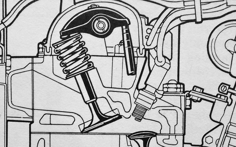 . | |||
Jeff Martin Experienced User Username: jeff_r_1 Post Number: 72 Registered: 07-2018 |
I don't think this drawing is correct, the intake valve is at an angle to the block, so is the exhaust valve. If I remember correctly, both valve heads are parallel to the deck surface. The spark plug is at angle, that's correct. Ironically, if that photo was correct, this thread would not have been started. | |||
Christopher Carnley Unregistered guest Posted From: 109.159.63.210 |
There is no section of the MKVI family engines that show the combustion chamber. This is the Rolls-Royce FB60 4 litre engine as designed by Reg Spencer. 1) If raised crown pistons were practical, R-R would have employed them as they did with the 1938 R-R Wraith, as the original compression ratio of 6.1 was found to be inadequate. 2) I have removed an R Type head and with a piston will show how impractical your idea really is. 3) Contact my client and friend Jeremy Padgett at Padgett Motor Engineers, the internationally regarded R Type and S1 Continental tuning experts, who follow the path outlined in my posts above. They regard raised crown pistons as sheer folly in these engines. 4) Have Bill Vatter make up a set and try them in his old Silver Wraith and then let us know the result. That is, put his money where his mouth is. (Message approved by david_gore) | |||
David Gore Moderator Username: david_gore Post Number: 3729 Registered: 04-2003 |
After posting Christopher's drawing and reading Jeff Martin's comment; I spent some time searching for suitable cut-away drawings of RRMC post-WW2 6 cylinder engines in an effort to verify Jeff Martin's comment with a conspicuous lack of success. I was hoping one of these would be in a spare parts list for EPW models but no such luck. | |||
Jeff Martin Experienced User Username: jeff_r_1 Post Number: 74 Registered: 07-2018 |
Here's a photo from Chesman Motorsport. The red area represents approximately where the piston is and where one could add a dome or an angle in green. 2 sets of 3 pistons would have to be CNC machined down to suit the angles of the combustion chambers. Personally if I had the resources, I would increase the combustion chamber by removing the purple area, and that would allow symmetrical machining of the piston head. Either a round dome, or an angle head facing towards the spark plug area, of course that would bring in the problem of symmetry again. Interestingly, that head you see from Chesman, is a new head that has been re-designed to increase the compression to 8:1, yet it looks just like any other. They make them for the Blizzard. https://www.blizzardmotorcars.co.uk/the-car?lightbox=dataItem-jv2h67v6 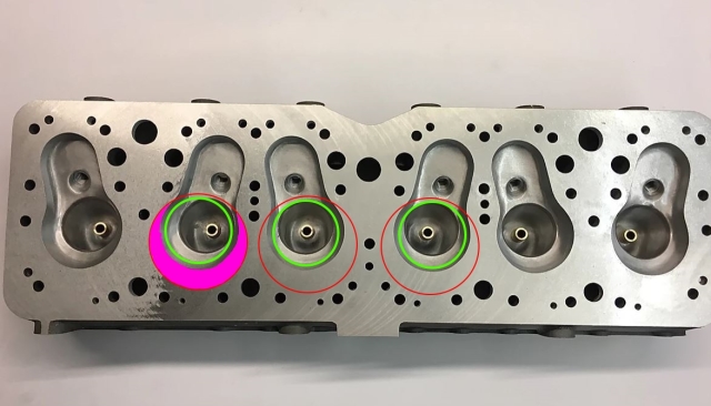 | |||
Christopher Carnley Unregistered guest Posted From: 109.159.63.216 |
The Blizzard, still in embryo stage is a project originated and built by Padgett Motor Engineers. I built the differential from a pile of bits and installed a 13:40 gear set. The head costs �10,000 plus VAT and has only the valves fitted. Raising the compression ratio to 7.1:1 in the R Type increased BHP by 1-2%, but the change from the constipating exhaust system absorbing 28 BHP to the twin pipe low loss one only taking 9 BHP, increased the net output. The bored out 4 1/2 litre engine for the 4.9 litre Continental only produced a maximum of 130 BHP net with an ultra low loss exhaust. The head design used only for Rolls-Royce and Rover customers is a flawed design, so it has big valves, the cooling of the exhaust valves and ports is very poor and the awkward combustion chamber is a bad choice. It is a version of the "L" side valve with a bit of squish It actually derives from the bad choice of Bentley Motors building the Ricardo head for the 4 litre W.O car, another waste of time. The OHV 3 1/2 litre Standard derived Jaguar engine was a much better design and more powerful. (Message approved by david_gore) | |||
Bill Vatter Experienced User Username: bill_vatter Post Number: 115 Registered: 09-2004 |
Here is the drawing that David Gore was referring to. That other drawing offered up by Chris.... It's not anything Rolls-Royce ever put in a production chassis marketed as a Rolls-Royce or Bentley. 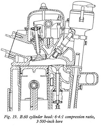 I have a couple of cylinder heads in my spare parts reserve. I measured the distance from the lowest point of the closed intake valve to the plane of the block mating surface for both a 4.25 head and an early (lower compression) 4.5 head. 4.25 liter engine: O.432 in. 4.5 liter engine: 0.516 in. I also measured the depth of the deepest point of the combustion chambers, which is immediately to the left of the spark plug. 4.25 engine: 0.939 inch 4.5 engine: 1.047 inch Somewhat larger combustion chamber volume is appropriate to maintaining the same compression ratio (6.4:1) for a larger displacement. | |||
Jeff Martin Experienced User Username: jeff_r_1 Post Number: 75 Registered: 07-2018 |
What did RR do to raise the compression to 8:1 ? Here is a reconditioned head from Flying Spares. Are the heads interchangeable between the 4.25 and 4.5, all they did was increase the bore size, are the stud locations the same ? https://www.flyingspares.com/shop/rolls-royce-bentley-cloud-s1-s2-s3/engine/silver-cloud-s1-engine/cylinder-head/cylinder-head-ue3764.html | |||
Bill Vatter Experienced User Username: bill_vatter Post Number: 116 Registered: 09-2004 |
Jeff, That link points to a late Cloud head. Nothing with CR that high made for the 4.5 L engine. 4.25 and 4.5 heads are similar but the stud pattern is different. The Cloud engine is very different from the earlier engines, and the cylinder head would not fit at all. The combustion chambers of the 4.25 and 4.5 cylinder heads are very similar and difficult to see the difference. The Cloud combustion chamber is quite different. By that time the RR engineers understood why milling the head caused troubles (choking the exhaust flow) and they redesigned the combustion chamber to increase CR without changing the flow path cross-section at the critical location. The attached drawing shows the differences in the combustion chambers of the two engines. 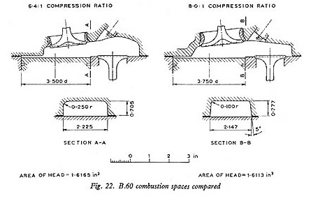 | |||
Christopher Carnley Unregistered guest Posted From: 109.156.42.107 |
The Chesman head is a copy of the S1 head, the later one with a milled face, and given 2" valves to raise it to 8.1. R-R had an OPWAS scheme, the head had a lower ceiling and gave 8.8:1, along with an hydraulic damper, it was for Rally Racing. Very unreliable if not maintained in constant tune and with 100 octane petrol. Due to one low core plug the S1 HC head can,t be milled any further. I am building up a high compression head to fit to an R Type block bored out to 3 3/4", the job is endless, and with so many gearboxes in for overhaul! The engine, B21U had been reconditioned at the factory and fitted with an S1 camshaft and new tappets etc, but the client wants a speedy 21" wheeled pre-war replica. When you have made 39 new studs out of EN16 steel you know what the job is all about. There was a paper presented to the Institute of Mechanical Engineers in 1963 by Harry Grylls, former Chief Engineer, called "THe History of a Dimension" ie 4.15", and is a treatise on the development of the Rolls Royce Engines. It can be downloaded from the KDA132 site. Happy readings. (Message approved by david_gore) | |||
Bill Vatter Experienced User Username: bill_vatter Post Number: 117 Registered: 09-2004 |
Incidentally, RR made a Cloud 4.9 engine with 10:1 compression ratio that developed 205 BHP, but it was never used in a production car. I do not know what they did to the combustion chamber to get the CR that high, but you can see that there are some places where the volume could be reduced further in the 8:1 CR head, and the throat section could be opened more at the same time. | |||
Jeff Martin Experienced User Username: jeff_r_1 Post Number: 79 Registered: 07-2018 |
Here's a member of the RR club in my area who is a commercial retired air craft mechanic. He planed the head on his 4.25 litre Dawn and took .065 off. He also had to shim the rocker pedestals that much as well. It raised the compression to 7.5:1, the readings are: 140,141 143 144 143 146. He very often won our fuel economy run in our region getting around 24 to 25 miles to the gallon. It is a 4 speed column shift with left hand drive and Stromberg carburetor. | |||
Bill Vatter Experienced User Username: bill_vatter Post Number: 118 Registered: 09-2004 |
Jeff, Thank you. Do you know if he did anything else to the cylinder head besides milling the surface? I think it might be appropriate to also open up that place shown in the section cut away shown in the drawing I posted above. | |||
Jeff Martin Experienced User Username: jeff_r_1 Post Number: 80 Registered: 07-2018 |
Hey Bill I know for a fact all he did was shave the top. He was not even aware of the exhaust problem. Is it even possible to physically open up that area ? From what I see in those photos, RR moved the intake valve away from the top of the piston to increase that space and decreased the space above the exhaust valve to further raise the compression. If you start removing material away from A-A, would that not lower the compression _ you have no way of filling in that dome above the exhaust valve. Still I suppose if one removed .072 thou in that area, and added that much to remove on the deck, with a max amount of the deck of .137 to get to where Tom's Dawn is ??? Get someone who welds aluminum to fill in that dome _ be tricky adjusting just the right amount of aluminum to get all the chambers the right size. It could be done with water and plexiglass, but what a tedious job. | |||
Christopher Carnley Unregistered guest Posted From: 109.159.63.175 |
That is only 1/16", so how did he know that he had raised the ratio to 7.5:1? Did he measure the capacity of the combustion chamber, or make a guess? The capacity of the combustion chamber is directly proportional to the C.R. Raising the compression ratio does more for the gas mixing as he has found. (Message approved by david_gore) | |||
David Gore Moderator Username: david_gore Post Number: 3730 Registered: 04-2003 |
Christopher has forward the following article for me to post on his behalf:-
. | |||
Jeff Martin Experienced User Username: jeff_r_1 Post Number: 81 Registered: 07-2018 |
Chris, I'm just printing what he wrote to me in an email, who know how much was taken off before ? But if you take one of his numbers like 144 psi. and divide it by atmospheric pressure at sea level (14.7 lbs PSI), you get 9.7 _ that makes no sense. I'll ask him. | |||
Jeff Martin Experienced User Username: jeff_r_1 Post Number: 82 Registered: 07-2018 |
Tom's words. When I did this I measured the cc of the combustion chambers and calculated how much to machine off the head.I believe I am within .1 of 7.5. I have .020 over bores = 89.408 mm stroke =114.3 mm . 89.408 x 89.408 x 3.14159 divided by 4 = 6278.3027 x114.3 = 717609.99 = 717.609 cc per bore . combustion chamber volume = 110 cc. Add 110 to 717.609 = 827.609 divided by 110 = 7.523 compression ratio. cheers Tom | |||
Christopher Carnley Unregistered guest Posted From: 86.182.78.138 |
Why has he divided by 4? (Message approved by david_gore) | |||
Jeff Martin Experienced User Username: jeff_r_1 Post Number: 83 Registered: 07-2018 |
Maybe he should have divided by 6 ??? I never looked at his numbers closely, been very busy doing other things. I'll sit down and see what's going on later. | |||
Patrick Lockyer. Grand Master Username: pat_lockyer Post Number: 2333 Registered: 09-2004 |
Maybe time for a newly designed crank shaft and new type pistons, re piston speed. | |||
Jeff Martin Experienced User Username: jeff_r_1 Post Number: 85 Registered: 07-2018 |
I'd settle for a more efficient combustion chamber and a better cam shaft. Why go to all this expense with the Blizzard and the La Sarthe and use such antiquated technology ? https://bensportltd.co.uk/la-sarthe | |||
Christopher Carnley Unregistered guest Posted From: 86.182.78.134 |
Reg Spencer did just that with the R-R FB60 aluminium engine, stiffer crank, shorter stroke,a rubber bonded damper, zero lash hydraulic tappets, 8:1 compression ratio. The BMC Service Manual claims 165 BHP, but that was actually the test engine with open exhaust. The real BHP at the wheels with full exhaust was more like 140 BHP. (Message approved by david_gore) | |||
John Rowney Experienced User Username: johnrowney Post Number: 85 Registered: 02-2015 |
The example of 144 psi measured with air in a cylinder does not give a pressure ratio of 144/14.7=9.7 A measurement by a gauge is the gauge pressure. Thus 144 psi(gauge) or 144 psig =144+14.7=158.7psi(absolute) or 158.7psia. The pressure ratio is then 158.7/14.7=10.8 The pressure ratio is not the compression ratio. Perhaps the compression ratio could be thought of as a volume ratio. 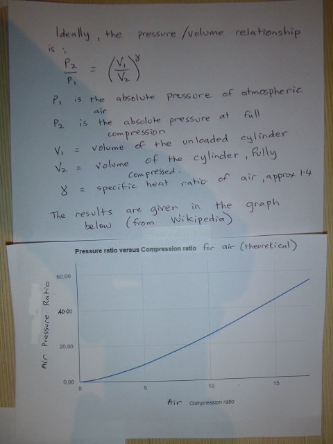 The graph is taken from Wikipedia under the subject Compression Ratio. Air in a compression test will not exactly follow the ideal equation, so there will be some difference in the actual pressure compared to the theoretical value. Measuring the maximum pressure in the cylinder is best used to determine differences in compression between cylinders. The graph could be used to give a reasonable estimate of the compression ratio, but an accurate value can only be determined by measurement of the volumes. 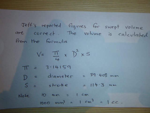 | |||
Bill Vatter Experienced User Username: bill_vatter Post Number: 119 Registered: 09-2004 |
I see compression pressure and compression ratio being used almost interchangably. They are not the same thing. Compression ratio is a calculation (vc+vd)/vc where vc is the volume of the combustion chamber and vd is the displacement, stroke*pi*bore**2 / 4. The compression pressure is a measured quantity, and compression ratio is only one of several parameters tbat affect pressure of the compressed fuel mixture. The pressure resulting from the fuel mixture compression is affected by many things like valve timing, throttle opening, and engine speed. You cannot predict compression pressure from compression ratio alone. When I read a certain pressure is indicated by a compression ratio, I cringe because that is flawed thinking. Raising the compression ratio will raise the compression pressure, but please don't try to quantify that relationship. I seek to raise the compression ratio, while recognizing modest compression pressure, which suggests this engine should be able to handle much higher compression ratio without problems. However, I also note the combustion chamber shape results in a realatively long burn time which makes detonation potentially more of a problem. Fuel available shortly after the war was very low octane, about 70 at best. Today's 87 octane is much better which should allow 8:1 or maybe even more before high octane fuel would be required. And oh by the way, we really should be calling it expansiom ratio because it is the the expansion of the combustion gasses after being burned that develops the power. More expansion means more energy converted from heat to kenetic energy (motion) You can retard the valve timing to lower the compression pressure which will inhibit detonation, and then increase the expansion ratio (commonly referred to as compression ratio) and this will significantly improve thermal efficiency and economy. It's what manufacturers do today with what they call an "Atkinson cycle" engine, running something like 13:1 "compression" ratio and intake valves staying open long after BDC with 87 octane fuel. (Not a true Atkinson cycle, but its what they call it.) Very high calculated compression ratio but not so high compression pressure to prevent detonation. Looking at the valve timing diagram, we can see the RR EPW intake valve opens very near TDC but stays open long after BDC, and an engine that does not operate at high rpm. It's an Atkinson cycle wannabe. I'm sure they knew what they were doing and did it like they did for very good reasons. I am not about to mess with the camshaft. | |||
Jeff Martin Experienced User Username: jeff_r_1 Post Number: 88 Registered: 07-2018 |
Thanks for that Bill. I spoke to my buddy Tom again, and what he posted about is to do with actual combustion pressure and all those figures are a formula that is used to find just that. He races vintage motor bikes and he has to know with in .1 decimal place what the combustion pressure is, (or if one wants, the actual compression ratio). Anything deviating from .1, will bring on disqualification. I have no idea how the formula was derived, but then again, I'm not Einstein. | |||
Jim Walters Frequent User Username: jim_walters Post Number: 318 Registered: 01-2014 |
You can't just say Tom races vintage motorbikes Jeff.  He holds world land speed records at Bonneville. 191.752 MPH on a Triumph Trident! A much braver man than I!! He holds world land speed records at Bonneville. 191.752 MPH on a Triumph Trident! A much braver man than I!! https://www.youtube.com/watch?v=M5bYASDn_og SRH8505 SRC18015 SRE22493 NAC-05370 www.bristolmotors.com | |||
Jeff Martin Experienced User Username: jeff_r_1 Post Number: 89 Registered: 07-2018 |
I had no idea ! Or at least I don't remember him ever telling me that. He must be quite modest. | |||
Christopher Carnley Unregistered guest Posted From: 109.154.24.49 |
Tom took the formula from an internet site, and that is where the "4" appeared. It makes for no allowance for gasket thickness, the fact that the piston doesn't reach the top of the block and that there is no such thing as as a perfect seal in that there is at least 10% leakage past the piston rings. (Message approved by david_gore) |