| Author | Message | ||
Brian Vogel Prolific User Username: guyslp Post Number: 113 Registered: 6-2009 |
Hello All, This topic arose elsewhere, on rollsroyceforums.com, from someone trying to set the timing on his 20/25. In this set of timing instructions, clearly a Crewe TSD scanned, in the TIMING - TO CHECK section step number two reads: Adjust the tappets of No. l cylinder to the flywheel marking clearance specified for the engine. In the same step on the RROC-Australia Pre-War Library instructions it reads: Adjust the tappets of No. l cylinder to the running clearance specified for the engine. Obviously, these can't both be correct. I'm presuming that all of the timing setup is done using the flywheel marking clearances and then everything is set back to the running clearances. If that's the case, the library version appears to have a major typo. Can someone definitively clarify? Brian | ||
Stephe Boddice Frequent User Username: stephe_boddice Post Number: 86 Registered: 2-2005 |
I have responded to this on the US site but to clarify for this posting : - The first reference relates to setting the valve timing when assembling the engine. (See TSD2022) The second reference relates to setting the ignition timing during normal servicing. (See TSD2066) | ||
David John Stacey New User Username: staceyd142 Post Number: 9 Registered: 11-2019 |
I�m setting up the valve timing after an engine rebuild (Bentley 4.5) and I�m having trouble interpreting the TSD. I initially assumed that the �Inlet Open� Mark on the flywheel (presumably 3 1/2 degrees ATDC) was the one to use but later in the instructions, it talks about later flywheels having degree markings and says for the Bentleys , the TDC Mark should be used. Is it the case that if you set up using the 30 thou rocker clearance at TDC before the tapped starts to move, the 30 thou gives you the 3 1/2 degree lag before the clearance is taken up and the rocker starts to open the valve? Any advice appreciated, David | ||
Trevor Pickering Experienced User Username: commander1 Post Number: 119 Registered: 06-2012 |
Hi David I have just rebuilt the engine of my 1953 Silver Wraith and the TSD says to set the tappet at .030" as you say but the 15 degree AFTER TDC mark on the fly wheel should be used. I hope this is correct but I have not yet installed the engine or tried to start it. regards Trevor | ||
David John Stacey New User Username: staceyd142 Post Number: 10 Registered: 11-2019 |
Hi Trevor, my book says 10 degrees after for the Wraith and Dawn! | ||
Trevor Pickering Experienced User Username: commander1 Post Number: 120 Registered: 06-2012 |
Ok thanks I will check mine again Trevor | ||
Christopher Carnley Unregistered guest Posted From: 109.156.245.163 |
Are you reading the Service Handbook, p B 21, where the text refers to later series cars? (Message approved by david_gore) | ||
David John Stacey New User Username: staceyd142 Post Number: 11 Registered: 11-2019 |
Yes Chris, it talks about the change to degree markings but goes on to say the Bentley and Phantom IV timing remains the same and should be set to TDC but it looks like someone�s been at work with the tippex... | ||
Norman Geeson Unregistered guest Posted From: 81.99.138.38 |
David �����.it talks about later flywheels having degree markings and says for the Bentleys , the TDC Mark should be used. Is it the case that if you set up using the 30 thou rocker clearance at TDC before the tapped starts to move, the 30 thou gives you the 3 1/2 degree lag before the clearance is taken up and the rocker starts to open the valve?.....� I am afraid you are misleading yourself with the data you have at hand. In fact the TSD that you are using will be of little help that is, unless you know the part number of the camshaft that is fitted. That part number is unfortunately stamped on the rear face of the camshaft. It is important to know which camshaft is fitted before attempting to set the timing. Not only did R-R use a large number of different camshafts but they also increased the positions of the inlet and exhaust peaks, and did so on more than one occasion and still kept the same part number!! If an appropriate camshaft is fitted to your Bentley 4.5 ltr (presumed R Type or MKVI) The timing will be Inlet opens at TDC with the tappet set at 0.030 inch, or the camrider lifted by 0.0234 inch, this to ensure an inlet valve opening around 26 deg BTDC when the engine runs. (Message approved by david_gore) | ||
David John Stacey New User Username: staceyd142 Post Number: 12 Registered: 11-2019 |
Thanks Norman, I can check the number on the cam but the engine is original in a 1953 R Type. So just to be clear, I time by looking for 0.0234 rise on the Number 1 inlet tappet coinciding with TDC lining up with the bell housing pointer. The 26 degrees BTDC is a new one on me though, quite a difference from the 3 1/2 ATDC book figure David | ||
David John Stacey New User Username: staceyd142 Post Number: 13 Registered: 11-2019 |
Have just spoken to an ex-RR mechanic here in the UK. He advised that inlet opening timings were revised over the years to improve performance and hence the shift from use of the IO Mark to the use of the TDC Mark. He said that he always sets these engines using a 30 thou gap and the pointer on TDC. Closing the gap back to running clearance therefore gives a valve opening slightly before TDC. His tip for judging the point of valve opening is to rotate the push rod and turn the engine until the rod just nips up. | ||
Christopher Carnley Unregistered guest Posted From: 109.156.245.173 |
Follow the book David and avoid the confusion, if the the camshaft is original to the car, the tips will be very worn, typically minus .060" to .090", and you will never get the factory original lift, anyway. (Message approved by david_gore) | ||
David John Stacey New User Username: staceyd142 Post Number: 14 Registered: 11-2019 |
That was my problem Chris, the book is contradictory and I reasoned that the initial reference to the IO marking (and the fact that there is one on my flywheel) was the way to set up and that the later reference to TDC was an error. I didn�t mark my gears when dismantling so I don�t know how the engine was set up from new. | ||
Patrick Lockyer. Grand Master Username: pat_lockyer Post Number: 2274 Registered: 09-2004 |
Long time ago but seem to remember I used a dial gauge on the No 1 cylinder tappets. Maybe Norman could advise? | ||
David Hughes Experienced User Username: wedcar Post Number: 107 Registered: 07-2004 |
David 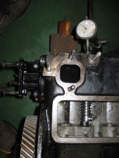 This is the set up I used on our Silver Cloud engine rebuild 12 years ago. Following the instructions in the manual. Simply a steel rod replacing the push rod, with a return spring added,checked with a dial indicator with piston at TDC Regards David | ||
David John Stacey New User Username: staceyd142 Post Number: 15 Registered: 11-2019 |
Thanks both, I�ll use that method and cross-check with the 30 thou push rod gap and see how close the results come. | ||
Christopher Carnley Unregistered guest Posted From: 86.163.222.56 |
David, Download Service Bulletin BB.91 from the library. See 3.(ii) on p3, then follow the Bench Type instructions. Ignore the camshaft confusion. (Message approved by david_gore) | ||
Christopher Carnley Unregistered guest Posted From: 86.163.222.56 |
The Silver Cloud camshaft is different. (Message approved by david_gore) | ||
Norman Geeson Unregistered guest Posted From: 81.99.138.38 |
David It is dangerous to assume that the car has the original engine that is untouched. Many of these engines had camshafts replaced during service periods without the owner knowing. Firstly, let us know the part number of the camshaft, chassis and engine number. It is a long and expensive task to strip down the engine again to find the camshaft part number, and it is vital to know that before setting the timing. Many years ago I was talking to the owner of the very first Bentley S1, who was assuring me that the engine was untouched. He changed his mind when I showed him documentation that not only had the camshaft and tappets been changed, but they had been changed for a different type of shaft and all before 2500 miles. Don�t get confused with flywheel markings and the required camshaft inlet opening position. If you need to be confident about the data you have been given, consider who advised you to take the following course of action, which is taken from the second paragraph of Bentley Bulletin BB.91 dated 8th October 1953 titled Valve Timing. ��.Basically, owing to the possibility of camshafts and flywheels having been replaced in service, valve timing should be carried out in accordance with the camshaft fitted and not necessarily in accordance with the markings on the flywheel fitted��� I should have explained the measurements more clearly, even though I was trying to keep it simple! The 0.0234 inch lift on a tappet corresponds to a valve lift of 0.030 inch at the valve taking into consideration a rocker ratio of 1.282:1. Sometimes it is useful to know that once the inlet valve clearance is set at 0.030 inch then camshaft movement equating to a cam rider lift of 0.0234 inch should take up the 0.030 inch valve clearance and bring the valve to the point where it starts to lift off its seat. I always set a dial gauge on the cam rider to check the lift. You would also be advised to check the crankshaft TDC position by dial gauging the top of pistons No.1 and No.6 below the block face and comparing with your flywheel TDC mark. This information is particularly helpful if timing takes place with cylinder head and/or flywheel removed. I see that you have never realised the setting positions �reverse engineer� back to an approximately inlet valve opening of 26 BTDC on the Bentley camshaft when the engine is running.. However I doubt you are on your own on that point. Owners and many specialists also do not normally understand that point, or that all these EPW six cylinders have an inlet valve opening period, in crankshaft degrees, far greater than equivalent Jaguar, Aston Martin, Ferrari, BMW etc, etc, at over 300 degrees. As this inlet opening period is extensive, if it is out of phase, then you will be interfering with the progress and speed of the gas flow in the inlet manifold. That inlet manifold has a volume of 1300cc to match the camshafts and timing. If you are fully rebuilding one of these engines you will find it worthwhile to compare and match the crankshaft damper spring poundage�s, and if you have a number of spare ones to exchange, also the inlet valve springs. The crankshaft spring drive poundage�s have a direct effect on the valve timing (and ignition timing) so it is wise to pay close attention to the springs and damper slip poundage. After satisfying yourself that the springs are matched and a new spring plate is fitted (this is vital) make sure the damper radial drive is centred. This centring of the radial position of the dampers is important and about 95% are off centre, meaning the valve timing is not correct. You will find many who do not understand either the problem or the necessity to solve it before carrying out the timing. To check the centre position it is necessary to have the sump removed and to view the crankshaft pinion from the rear. Close examination will show the crankshaft pinion has slots machined in the body forward of the actual gear teeth. These slots allow the friction drum to rotate relative to the crankshaft pinion under influence of the radial drive springs. If the drive is off centre then the valve timing will be wrong and pressure must be taken off the damper to allow it to re-centre itself. It is possible to make up two small blocks that can be inserted in the slot spaces to keep the damper centred during valve timing. If you are trying to set the valve timing without keeping the damper centred then you will be wasting your time. For the record no post war 4.5 ltr MkVI or R Type Bentley was ever instructed to be timed after Top Dead Centre (ATDC). Such timing was only used with camshaft part number RE5157 on 4.25 ltr engines in MkVI chassis prior to chassis B 501CD. Undoubting, a 1953 Bentley would be expected to have a camshaft fitted that would demand a 0.030 inch inlet tappet clearance and timed at Inlet opening at TDC. However a number of these engines have been previously fitted with early Bentley or early Silver Wraith/ Dawn camshafts that require a different timing approach, and as I say, you need to ensure you do not have one. (Message approved by david_gore) | ||
Trevor Pickering Experienced User Username: commander1 Post Number: 121 Registered: 06-2012 |
I will now check my camshaft number but how do I find out what timing settings to use once I have confirmed what camshaft I have? | ||
Norman Geeson Unregistered guest Posted From: 81.99.138.38 |
Trevor You might try the following method to gauge the cam shaft type fitted to your car that would save you stripping it down. Unfortunately you have committed the worse sin by not listing the chassis number.!! Basically you need to check whether the engine is fitted with a RE 3672 camshaft, the ORIGINAL norm for a SWB Silver Wraith, or one of the many Bentley R Type or S1 camshafts. Both late Bentley R Type and S1 camshafts were fitted in LWB Silver Wraith engines and as replacements for all engines. The last recommended R-R modification was to use the S1 type camshaft. The odd, but possibly standard, camshaft you need to identify is the RE 3672 as this was set 10 ATDC inlet opening and must not be advanced as the inlet cam opening profile is very much different to the other camshafts. One point helps us here. The RE 3672 has a cam peak rotation between the Inlet and Exhaust peaks of 113�15� degrees. The Bentley / S1 camshafts on the other hand have Inlet to Exhaust peaks of between 109�48� degrees and 111�.18� degrees. If you mount a disk on the crankshaft marked off in degrees, with an adjacent pointer you should be able to rotate the engine to check the peak cam lifts. Remember these measurements are CAMSHAFT degrees and will double for Crankshaft degrees. All you are looking for is whether you have the wide angle RE 3672 camshaft. You will in any event need to centre the damper before proceeding. Once you have that data we can move forward. (Message approved by david_gore) | ||
Christopher Carnley Unregistered guest Posted From: 109.156.245.160 |
Whatever camshaft you have they will all be so worn as to make no difference at all. Set them to TDC in the Rolls-Royce prescribed method. The S1 camshaft with full width lobes, as opposed to the 50 degree lobe cut off angle for the pre 55 cars, UE3736 had the cam wheel set screw attachment holes rethreaded 1/4" BSF and used in MK VI/Rtype overhauls when the stocks of the early cams ran out, renumbered RE 23639. I am using one of these camshafts ex Jack Barclay in an R Type engine rebuild. (Message approved by david_gore)} | ||
David Gore Moderator Username: david_gore Post Number: 3637 Registered: 04-2003 |
Christopher has forwarded the following camshaft photo and comment to accompany this post: "Would you post this picture of EU3736 /RE23639 under discussion please? It was slightly confusingly listed as "low lift" which it is, but the S1 exhaust lobe is much larger." 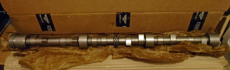  | ||
Trevor Pickering Experienced User Username: commander1 Post Number: 122 Registered: 06-2012 |
Many thanks Norman My chassis number is BLW66 As the engine is not yet fitted can I just remove the flywheel and take the end plate off to expose the end of the cam shaft and see what number is stamped there. I confirm that I have originaly set the timing to 10 degrees ATDC as per the "book" and not 15 degrees as previously stated. | ||
Christopher Carnley Unregistered guest Posted From: 109.156.245.193 |
The Silver Wraith settings are to make the engine a bit softer, the original cam peak was .005" less than the MK VI, but they are all very worn now. (Message approved by david_gore) | ||
David John Stacey New User Username: staceyd142 Post Number: 16 Registered: 11-2019 |
OK, so I�ve identified my cam and it�s an RE19517 so I�m TDC for the timing. I thought the crankshaft pinion was keyed on the crankshaft but now realise it�s the damper disc that�s keyed leaving the pinion free to oscillate. | ||
Bill Vatter Experienced User Username: bill_vatter Post Number: 82 Registered: 09-2004 |
I think it might be helpful to have knowledge of engineering principles that affect how a cam lobe is shaped. With that, some of the apparently strange and confusing data will become clear. One very important design objective is to minimize the pressure of the tappet against the cam. This is about wear. Springs should be strong enough to keep the tappet from floating off the cam lobe, but not stronger. The dynamic forces of the moving parts must be controlled by the valve springs which, if stronger than necessary, would cause excessive contact pressure. The dynamic inertia forces are the design basis for the spring. Force = mass * acceleration, so minimal acceleration is indicated. To get the valve open the tappet does need to accelerate, but this should not at any time be greater than necessary. This all indicates that the lobe is designed for constant acceleration throughout the entire time the valve is off its seat. That is how the lobe is shaped....for constant acceleration of the tappet, the valve, and everything else. It is the predominant design attribute of all camshafts for all cars, including all Rolls-Royce and Bentley cars. Constant acceleration means the parts begin moving quite slowly, and, with constant acceleration, speed up, then slow down, stop, start moving in the opposite direction, speed up, slow down, and stop as the valve meets its seat. So if you set the valve timing at the point when the valve begins to open, you are setting it at a point where the change of the valve position is very small compared to the change of the rotational position of the camshaft and crankshaft. It is a problem, but wait, it gets worse. The camshaft is made with an "approach ramp" at the place where the lobe begins to move the tappet. The approach ramp is designed to take up the running clearance very slowly as the clearance closes, so the contact occurs softly. That is what makes the valve linkage quiet. Virtually all solid lifter camshafts have this feature, while camshafts designed for use with hydraulic tappets do not. Hydraulic tappets have zero running clearance, and soft contact is not a consideration, therefore no approach ramp. If you have ever heard a "hydraulic" camshaft running with solid tappets, good grief, what a noise. That's because there are no approach ramps in the cam profile. The approach ramp is also present at the place where the valve closes so that it closes with soft contact. Valves closing on their seats with a bang causes significant wear on the contact surface of both the valve and the valve seat. This is the reason for lead additive replacements, which result in cushioning the closure contact. It is a reason for hard steel valve seats added in modern times to some older engines, designed in the days of lead in the fuel. Of course the faster the engine runs the harder the valve closure contact, so this is of greater consideration in high rpm engines. Rolls-Royce engines have neither agressive cam profiles nor are they run at high rpm, and therefore, the valve contact with the seat is not harsh, they do not need any lead-replacement additive in the fuel. Of incidental interest, hard steel valve seats are a good idea in the RR EPW SIx, but not to prevent valve and valve seat contact wear. Very hot temperatures at and near the valve seat sometimes result in cracks in the block deck, usually beginning where the valve contacts the seat. A hard steel seat is stronger than the cast iron of the block, and it is resistant to cracking. How can you tell exactly when the tappet begins to move (open)? Answer, you can't tell, at least not with much accuracy, and this means setting the timing when the valve begins to open can result in large errors. This is exactly how the Silver Ghost engines were set up, because in the beginning, this problem, or perhaps a way to avoid the problem, were not recognized. As a result, setting the valve timing on a Ghost is very tricky, requiring great care to get it right. There are also no approach ramps on a Ghost camshaft, and the running clearance is set very closely (0.002 in.) to make it quiet. Most owners choose to avoid risk of burned valves if the valve doesn't firmly contact its seat and use 0.004 for the running clearance, sacrificing some silence. Notice the prewar valve timing instructions begin with the New Phantom, and the Silver Ghost is curiously omitted. All cars after the Silver Ghost used a "Flywheel marking clearance" to set the valve timing. There are actually no instructions published for the Silver Ghost valve timing, but that was before the days of factory service instructions being generally available for anything. Use of the flywheel marking clearance, 0.030 inch for most cars, really means you are setting the timing at a point significantly after the point where the valve begins to open in operation, and this method is used to improve accuracy. When the valve is 0.030 (less the normal running clearance) off its seat, it is moving sufficiently fast, in respect to engine rotation, that the timing can be set with acceptable accuracy. The valve actually begins to open a good bit earlier, and the open duration is also a good bit greater than the degree specifications imply, including those indicated with flywheel marks. Some confusion results from referring to the marks as "inlet opens," etc. That point is not where the inlet really begins to open. It really opens earlier. Some points, such as using 0.024 in place of 0.030 if you are referencing the pushrod instead of the rocker arm end are very important. The wind-up of the damper springs and crankshaft pinion, including the damper being fully seated and tightened on the crankshaft taper are also quite important. There are a multitude of ways you can make a mistake and get it wrong. The specifications for setting the valve timing are in the book, and I do not think they changed much. There is a difference in the timing for Rolls-Royce vs Bentley engines, because RR owners valued smoothness more than power in contrast somewhat with Bentley owners. I believe there also was a change from 2 degrees ATDC to TDC (or vice versa), and the words late is better than early if you must be not quite on the exact point. I think doing it to the factory specifications is the right way. Read the instructions, including the Bulletins. In the same way as the points of the above discussion, determining the precise location of TDC is a very similar problem. You cannot directly measure with precision the exact rotational point where the piston is at its highest. Therefore, you measure where it is some distance below its highest both before and after, and TDC is imputed to be half way between these rotational positions. Of possible anecdotal interest, when assembling my Silver Ghost engine, I checked the flywheel marks for accuracy, comparing this imputed TDC with the TDC mark on the flywheel. I was surprised to find the flywheel marks were off by more than 5 degrees, in different amounts and directions for the three positions marked on the flywheel. The early engines, as excellent as they were for their time, are really not all that good by today's standards. In about 2006, I wrote a comprehensive article that was published in the US Club magazine, The Flying Lady. This describes in detail with pictures how to set the valve timing when assembling an EPW six-cylinder engine. It is a somewhat complex process to get it right. If you want a copy, provide an email address. | ||
Bill Vatter Experienced User Username: bill_vatter Post Number: 83 Registered: 09-2004 |
For Trevor, I believe setting the valve timing at 15� ATDC is wrong, and this will have a significant affect on engine performance. The factory stated something much closer to TDC. Changes to how the flywheel is marked are not changes to the timing specification, only a different way of marking the flywheel. | ||
Christopher Carnley Unregistered guest Posted From: 109.156.245.193 |
That would apply to any camshaft. I would be very interested in the dimension over the tips of all the cams, E.I.I.E from either end, and so on. The damper drive springs have to be in good condition, or the assembly will rattle, older engines will have sludged up and seized dampers,so you can't hear them. (Message approved by david_gore) | ||
Norman Geeson Unregistered guest Posted From: 81.99.138.38 |
Trevor You should be able to obtain access to the camshaft by the method you have indicated. Let us hope the shaft is clearly marked. These early LWB Silver Wraiths had three or four different camshafts, half with full width cams, and your engine is listed with the initial Bentley type RE 6885. Making matters more uncertain is that quite a few LWB Silver Wraith engines were reworked out of warranty and fitted with one of the four full width cam type of shafts. This, in a partial effort to cure exhaust noise. As these LWB cars often covered very little mileage the engine may have the original camshaft in very good condition. I am afraid it does look likely that the engine will need re-timing forward to inlet opens at TDC. I do have all the drawings and archive information for the post war six cylinder camshafts, about ten in total. These formed a long but not quite finished article I started back in 2003, after I had spent some days in the archives. Obtaining the correct data for your shaft should not be a problem. Keep us informed about the camshaft type and give me a ring, I have lost your number. (Message approved by david_gore) | ||
David Gore Moderator Username: david_gore Post Number: 3639 Registered: 04-2003 |
I would like to personally acknowledge the regular contributions of my two favourite forum "lurkers" to our Early Post War topics immediately above this post. They never fail to promptly offer advice immediately one of our members asks for help. In almost all instances, the information is the result of their own experience and undocumented knowledge provided to them by other custodians who have experienced difficulties. You both deserve the honorary Australian accolade of being "a great mate" and with this comes my personal thanks for your help, advice and contributions for the benefit of all who access this forum. Thank you and I look forward to your future participation when appropriate. | ||
Trevor Pickering Experienced User Username: commander1 Post Number: 123 Registered: 06-2012 |
Well said David | ||
Trevor Pickering Experienced User Username: commander1 Post Number: 124 Registered: 06-2012 |
Thank you Norman and Bill I will remove my flywheel and cam shaft cover to reveal the number on my camshaft next week and will post my findings. I am self isolating at the moment and so have plenty of time! I will send you a PM with my contact details Norman Trevor | ||
Bill Vatter Experienced User Username: bill_vatter Post Number: 85 Registered: 09-2004 |
The camshaft wear tolerance is referenced to the distance across the cam from tip to heel. Something on the order of 0.010 less than the original dimension is allowable, but one needs to know the original dimension. The dimension of interest for early camshafts, The "high-lift" used the first Bentleys, the first Silver Wraith camshaft, and possibly also the "low-lift" that superceeded the high'lift in Bentleys can be found in the combined book that covers all the then-current models, both RR and B, I think that book can be accessed on the RROCA website technical section. The dimension, distance across the cam lobe, is given with the part number, RExxxx, which is stamped on the back end of the camshaft. You do need to know what camshaft is in your engine, and that might be difficult. As Norman said, many have been changed. If you know what camshaft you have, you could measure the cam lift with a dial indicator on a pushrod end, and use that instead. I believe the lift is also published in the combined service manual, but be careful, the valve lift differs from the cam lift by the rocker arm ratio. Cam lift * rocker ratio = valve lift. As Norman said, there were many camshafts. I think, but don't know for certain, all of the subsequent camshafts had the same lift as the first Bentley replacement camshaft, the one the factory called "low lift." Perhaps Norman can verify that. | ||
Bill Vatter Experienced User Username: bill_vatter Post Number: 86 Registered: 09-2004 |
Chris referred to the damper rattling because of weak internal springs. That is different from the rattle discussed in most publications about RR vibration dampers. The commonly discussed rattle comes from the gears, not the damper itself. | ||
Christopher Carnley Unregistered guest Posted From: 109.159.182.143 |
Bill, If you read what I wrote, you will see that I said that the springs need to be in good order when refitted, or the assembly will rattle. This is not from a book, this is from a car that came in, and rattled from a bad damper rebuild. The best MK VI that I tried in recent years was an early one that had been in France most of its life. It was smoking and needed a Scheme B filter fitted. The performance of this car on the first meeting was exceptional, when I dismantled the engine, not only was the original chrome plating still on the cylinder bores, but it had the original high lift camshaft RE.5157,still within the -.012" wear limit and the tappet faces were unmarked. (Message approved by david_gore) | ||
Bill Vatter Experienced User Username: bill_vatter Post Number: 87 Registered: 09-2004 |
Chris, That's right. You did not specifically say the damper itself rattles. I inferred that from your statement that "older engines will have sludged-up and seized dampers so you can't hear them." What's producing the rattles really doesn't make much difference. What matters is that rattling from the front of the engine is indicicative of a damper needing help. I probably shouldn't have made the post that disagreed with you. Perhaps in the interest of friendly relations. David will want to remove the applicable comments. Moderator Comment: Unfortunately, due to time zone differences I did not have the opportunity to do this immediately and I am currently having problems with my mobile broadband internet connection in Sydney due to the increased traffic from people working from home following our shutdown of businesses due to the Corona Virus epidemic. . | ||
Christopher Carnley Unregistered guest Posted From: 86.182.76.62 |
Your contrition is enough, but I really don't understand your 4th sentence. (Message approved by david_gore) | ||
Bill Vatter Experienced User Username: bill_vatter Post Number: 88 Registered: 09-2004 |
Chris, In what way do you not understand? I only tried to say that from what you wrote, which I copied in quote marks in my post, I thought you meant a sludged up and seized damper will not rattle. In other words, I got the thought from what you wrote. That is what the word 'inferred' means. Since you seem to want to continue the discussion of that point, I also think your statement is actually wrong, but I chose not to say that before. A sludged up seized condition will most likely do the reverse of what you stated, i.e. cause rattles rather than silence rattles. Gearcase rattles are due to an ineffective damper that results in a the pinion gear vibrating against the camshaft gear producing a rattling sound, or in the case of prewar cars with more than two gears, multiple contacts in the gear train. For early cars that still have the fabric camshaft gear, if any of those are still in service, the further result is destruction of the gear teeth on the fabric gear. Cars with an aluminum gear just rattle, I have seen what appears to be surface fatigue marks on the aluminum camshaft gears, which I believe come from an ineffective damper causing a vibrating contact, but I have not seen an aluminum camshaft gear with broken or stripped gear teeth. A seized damper is one way, but not the only way, the damper can be ineffective. Incidentally (Or perhaps this is my main point?), I further object to your use of the word 'contrition,' and that has raised my ire somewhat. My attitude towards what you wrote is certainly not contrite. If you thought I was humbly begging forgiveness, you got that wrong. I only wanted to avoid a nasty exchange like what I have experienced before when I disagreed with something you wrote. | ||
Norman Geeson Unregistered guest Posted From: 81.99.138.38 |
DAVID COULD YOU SEND YOUR E-MAIL ADDRESS TO ME AT MY E-MAIL ADDRESS, SO THAT I CAN SEND YOU SOME SKETCH DETAILS OF THE POST WAR CAM SHAFTS. MANY THANKS NORMAN NORMAN GEESON Norman - thank you for your kind offer - I have emailed the appropriate email address for this purpose to you at your Gmail address. (Message approved by david_gore) | ||
Christopher Carnley Unregistered guest Posted From: 86.137.245.141 |
Typically, your desire for "oppositionalism" continues. Like your erstwhile troll friend, you should read what is written, and avoid making trouble for yourself and other people. Chat rooms are potentially dangerous places, where there is no place for people with grudges, new or old. (Message approved by david_gore)}} | ||
David Gore Moderator Username: david_gore Post Number: 3645 Registered: 04-2003 |
Gentlemen - please agree to disagree on this topic and move on. You all may be right to varying degrees and the final outcome will depend on what David Stacy and Trevor Pickering actually discover as they work through their repairs. Hopefully, when they succeed, they will post the outcomes so we all can benefit from their experience. | ||
David John Stacey New User Username: staceyd142 Post Number: 17 Registered: 11-2019 |
Satisfied that I�m timing from the TDC Mark, I used the dial gauge on the tappet method and cross-checked with the 30 thou rocker clearance method and the results from both methods were in precise agreement. Engine not ready to run yet but I�m a lot more confident that when I first started. Thanks all for the advice. | ||
Trevor Pickering Experienced User Username: commander1 Post Number: 125 Registered: 06-2012 |
I will remove my flywheel and cam back plate today and publish the cam part number if I can read it. If Norman or Bill could comment on the correc timing settings for my cam it would be much appreciated. I did not know there was such a large number of different cams fitted! What a great place this forum is. | ||
Jeff Martin New User Username: jeff_r_1 Post Number: 21 Registered: 07-2018 |
On a strait 6 engine when number 1 is on compression, the exhaust and intake cam lobes for number one are facing up and pointing away from each other at their extremes, 2 and 10 o'clock ??? I found this to be true for inline 4 cylinder engines as well. Wouldn't it be easier just to place the lobes at 2 and 10 o'clock with number 1 at TDC and be done with it ? | ||
David Gore Moderator Username: david_gore Post Number: 3649 Registered: 04-2003 |
Norman Geeson has forwarded the photographs below for me to place on the forum so he can prepare comments for me to include with the photos. Your co-operation with Norman's request for attribution will be appreciated: "I have numbered the image files so that I can comment on them once they are listed. The images are copies of ones I produced for my original camshaft article (as yet unpublished). In that connection I expect readers who wish to use the data to acknowledge the source." 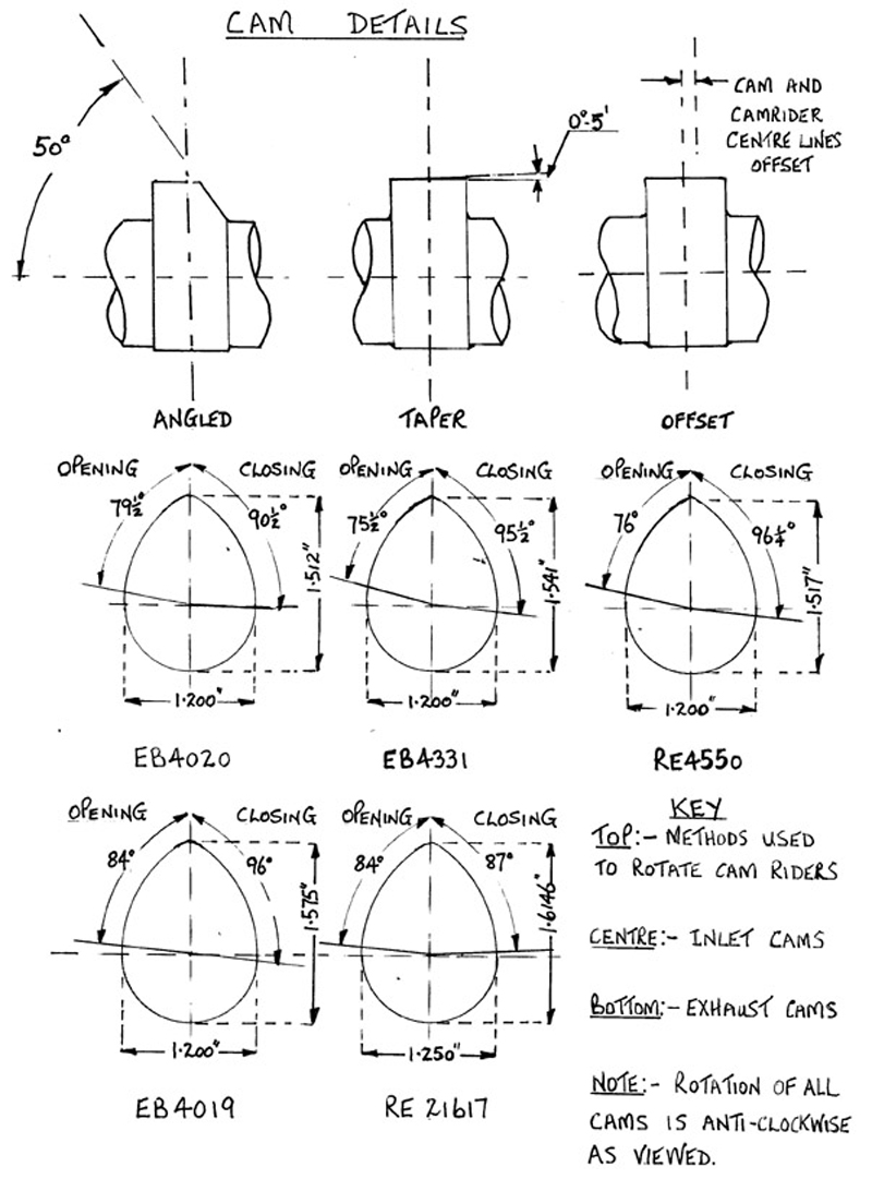 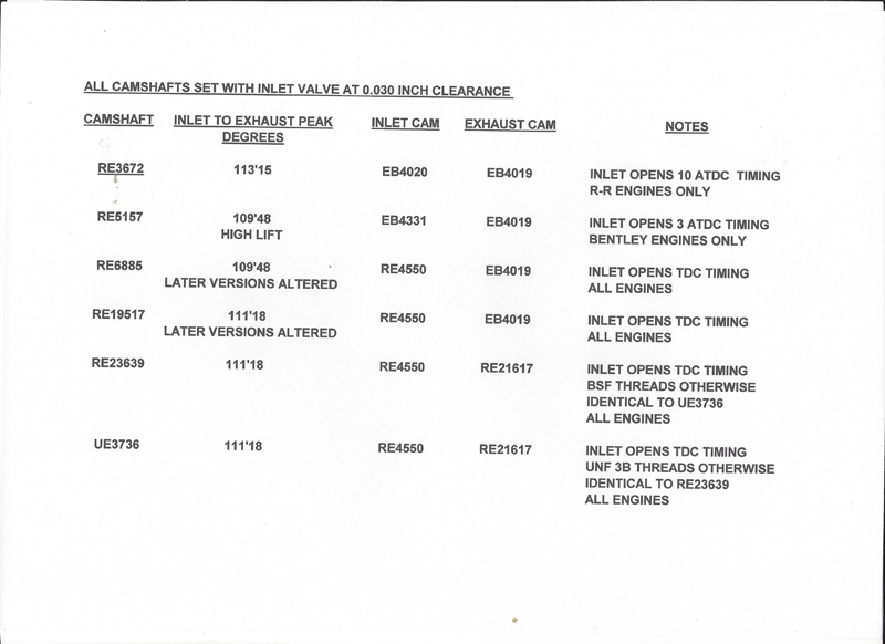 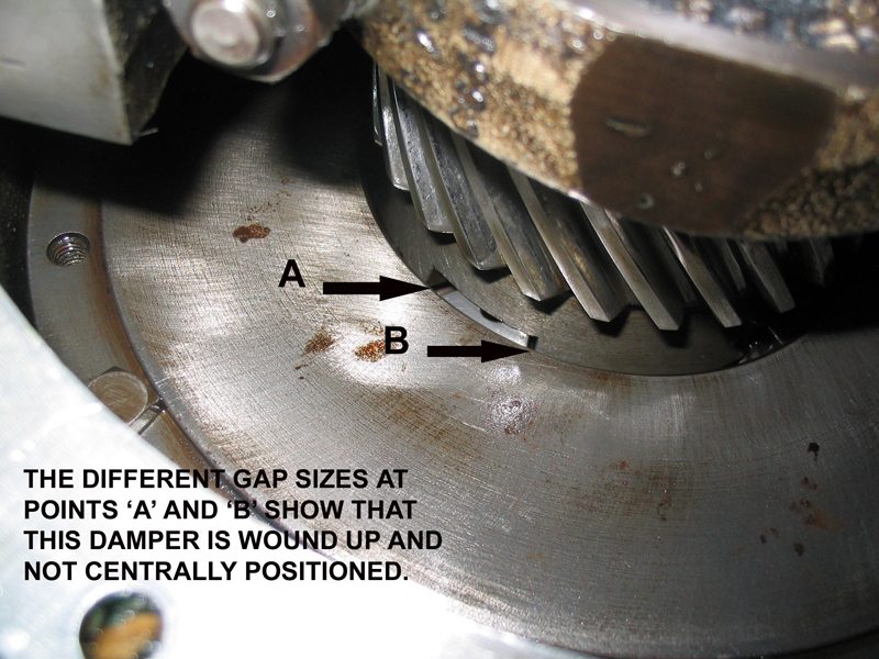 | ||
Christopher Carnley Unregistered guest Posted From: 86.182.212.115 |
All you need to know is in the Service Bulletin, the rest is pure waffle an oppositional "I know more than him", and does nothing but confuse. (Message approved by david_gore) | ||
Bill Vatter Experienced User Username: bill_vatter Post Number: 89 Registered: 09-2004 |
Hi David, Thanks for your reminder. Trevor, Norman may know the data specifics for your camshaft, but I do not. I can speak to METHODS I know will result in success, but the not the specifications. I think that if you know the camshaft number, you can first check that it is within the wear tolerances, and then using correct timing specifications, you can time it being careful to not introduce error, and everything should be well. I would like to point out one place not mentioned in the factory instructions or previously in this thread where an error might be introduced. I noted duing assembly that the axial position of the damper can produce an error. This is because of the helical gear form. Move one gear in the axial direction will cause the other gear to rotate. When you install the damper, you slide it onto the crankshaft taper and it will make contact before it is fully seated. If you leave it in that position (on but not tight) while you set the timing, the timing will change when you later tighten the damper onto the crankshaft taper. Could be as much as 0.060 inch axial movement when tightening, which will rotate the camshaft several degrees. I took a picture indicating this source of error and it's magnitude, and when I have a quiet moment I will look through my picture files and post it here. Other than that, I believe Norman has touched on all the opportunities for error. | ||
Trevor Pickering Experienced User Username: commander1 Post Number: 126 Registered: 06-2012 |
Thanks Bill I will post tomorrow with details of my cam shaft. Thanks also to Norman for the information | ||
Patrick Lockyer. Grand Master Username: pat_lockyer Post Number: 2282 Registered: 09-2004 |
Keep it simple, use the camshaft that is in your engine if in good order. Use a dial gauge and set to the data given for the engine camshaft type. As Christopher C said [ the rest is pure waffle] And at a heavy cost on time! | ||
Trevor Pickering Experienced User Username: commander1 Post Number: 127 Registered: 06-2012 |
Time is not an issue for me as we are in "lock down" because of Covid 19 and will be for the next 12 weeks! My engine is not in the car so its only 1/2 hour to get the number from the back of the shaft. This wayI will be sure to get it right and not have to worry when the engine is re installed in a few weeks time.  | ||
Christopher Carnley Unregistered guest Posted From: 86.131.42.233 |
Well Patrick, at least there is one other person contributing who has a sense of reality, and not another with self congratulating conceit. Let the engine speak and all the camshafts under discussion are worn to buggery, way below the case hardening depths. (Message approved by david_gore) | ||
Trevor Pickering Experienced User Username: commander1 Post Number: 128 Registered: 06-2012 |
I have now removed the cam back plate and can confirm my camshaft is Part Number RE 23639. If someone could contact me with the correct method to follow now it would be much appreciated. I understand the importance of centering the damper. I find the instructions in the manual some what confusing Must be my age! From Normans drawings it looks like the timing should be set at TDC Thanks again | ||
Trevor Pickering Experienced User Username: commander1 Post Number: 129 Registered: 06-2012 |
Just had a good chat with Norman and he confirmed that with my shaft the timing is set at TDC. This confirms that it pays to check which shaft you have PRIOR to setting up your timing and not to rely on the manual. What a good job my engine is not in the car. Thanks again to all | ||
Bill Vatter Experienced User Username: bill_vatter Post Number: 90 Registered: 09-2004 |
Chris C. wrote, "Let the engine speak and all the camshafts under discussion are worn to buggery, way below the case hardening depths." That may be true, but perhaps there are a few out there that are still serviceable. I did a major overhaul of My Silver Wraith, WGC-66 engine, W265C, in 2004 and I had some historical mileage documentation leading me to believe the mileage showing ~20,000 was actually ~120,000. Also, the old worn out bearings were all standard size, the pistons were also all standard size, and the camshaft was RE3672, fit to only early Silver Wraiths and Silver Dawns. I don't believe that camshaft was provided by the factory as a replacement part for very long. Based on that I concluded the engine had not been overhauled before, and the camshaft was the original one fit when the car was built. When I measured the camshaft, I did find that one or two lobes (not all) were worn more than the factory allowable tolerance, 0.016 inch across the largest distance from heel to peak, but they were not a lot out of specification. From that I conclude it is possible the camshaft in any car could possibly be serviceable, but it would be prudent to check that. Norman's sketch, posted by David Gore above, provides data from which the cam lift of the lobe profiles used on certain camshafts can be calculated. For example, the intake cam lift of Trevor's camshaft RE23539, would be inlet lobes, profile RE4550, 1.517-1.200=0.317 in. and the exhaust cam lift, profile RE21617, 1.6146-1.250=0.3646. It would not be difficult to set up a dial indicator to measure the pushrod motion and determine the actual lift of the installed camshaft, and subtracting that from the calculated as-manufactured cam lift, the amount of wear the camshaft lobes have. When doing that, it would be important to ensure there is no slack in the valve linkage through which the measurements are obtained. I note the service instructions and Norman's data match, with the exception that in the books available to me, neither the early Bentley "High Lift" camshaft nor the late UE23639 and UE3736 camshafts are addressed. | ||
Bill Vatter Experienced User Username: bill_vatter Post Number: 91 Registered: 09-2004 |
Referring to my previous post where I cautioned to set the timing with the damper tightened on the end of the crankshaft and not when the damper is in place but not tightened. Note in picture 1 the gap between the pinion gear and the first main bearing journal, forward edge of the journal just visible. Then see in picture 2, the gap has closed with the damper fully tightened onto the crankshaft taper. This position change will affect the timing and not timing with the damper tight on the crankshaft introduces an error. You may also notice in picture 2 the front of the damper flywheel is not tightened to the rear, which needs to be done, but does not change the position of the pinion gear. In both pictures, you can also see one of the holes drilled to allow oil to flow through the damper and not be trapped within. This prevents buildup of sludge and water, which can contribute to corrosion which can cause the damper to seize or interfere with the friction properties. 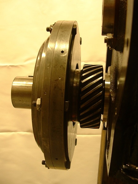 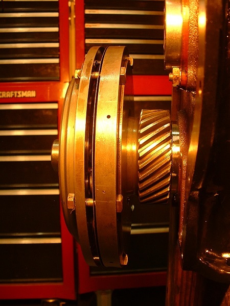 | ||
Trevor Pickering Experienced User Username: commander1 Post Number: 130 Registered: 06-2012 |
Very interesting Bill My damper is bolted up tight and in position as I was very close to re fitting the engine in the car. Now I know about my cam I will have to remove the timing case and start the correct timing process. Very happy to now have the correct info. | ||
Patrick Lockyer. Grand Master Username: pat_lockyer Post Number: 2283 Registered: 09-2004 |
"but they were not a lot out of specification. From that I conclude it is possible the camshaft in any car could possibly be serviceable." Really, refitting a cam below makers tolerance is bad news, once the lobe wear has taken it's course the case hardening is worn and well on its way. With the old type oils that some use the start up clatter will result with running noise getting worse. | ||
Norman Geeson Unregistered guest Posted From: 81.99.138.38 |
Trevor You are correct that cam shaft is timed at TDC. Two things of note. (1)That engine has been fitted with a replacement shaft in its service life because that shaft was only used for spares. It is a full width lobe cam. (2)As you were working on a Silver Wraith you followed bulletin instructions for that model. As I have said many times it is vital to check which camshaft is fitted before proceeding. In addition I would gamble that the shaft is in good condition. I hope that at least some readers might gain from the experience and realise that there are still some "specialists" that are lacking in experience. (Message approved by david_gore) | ||
Christopher Carnley Unregistered guest Posted From: 109.156.42.11 |
You will note that RE 23639 is shown in the photograph above. The presence in you car engine show that this was fitted at overhaul sometime after 1955. This is the modified S1 camshaft, and used when the Bentley R Type ones were used up. I know this as I used to fit them during my apprenticeship at Appleyards in Leeds. (Message approved by david_gore) | ||
Trevor Pickering Experienced User Username: commander1 Post Number: 131 Registered: 06-2012 |
Thank you Chris | ||
Jeff Martin New User Username: jeff_r_1 Post Number: 24 Registered: 07-2018 |
After discussing this with my machinist, I believe that RR has made something more complicated then it has to be; as usual. If I was rebuilding my engine again, I would use a dial gauge to get TDC on number 1 compression. At that point the intake and exhaust lobes for number 1 should be pointing equally furthest away from each other. That puts number six cylinder at the bottom of the stroke and the lobes on the cam shaft would then be pointing equally to each other on number 6. If everything is correct, then the lifters for number 6 would be open equally, one on it's way to be fully open, the other on it's way to fully being closed. If one uses the method from Rolls Royce, the camshaft position can be easily checked by removing the access cover where the exhaust valves are adjusted and noting the position of the lifters for intake and exhaust, they should be in the equally closed and open position for number 6. It will be as close as possible what ever method is used, allowing the fact the camshaft will be adjusted as such with one gear tooth before or aft. | ||
Bill Vatter Experienced User Username: bill_vatter Post Number: 93 Registered: 09-2004 |
Not sure I understand method described by Jeff Martin 4/20/2020. Jeff, are you saying that at TDC 360 degrees from spark, the TDC that occurs between between exhaust and intake strokes, the intake tappets and exhaust tappets are up from lowest positions by equal amounts? If my understanding of your post is correct, I am quite surprised by this information, and I do not think that would be what one would find with a camshaft that has been correctly timed. Also your last paragraph is not clear to me. This seems to imply one can only get within + or - 1 gear tooth of exact. That is most definitely wrong. According to factory instructions, it is possible to get much closer than that, and when I have done it, I have been able to get within 1 or two degrees of exact by crankshaft rotation. Increased precision (better than within + - one gear tooth) is made possible by the gear being bolted to the camshaft in either 4 or 8 different ways depending on camshaft and gear in the engine. (4 or 8 studs) Repositioning the gear on the camshaft will change timing by less than one gear tooth, by factory instructions that's 1/4 or 1/8 tooth respectively, but in practice I recall it is not exactly like that. Some camshafts have 4 studs and others have 8, but I think that because the gear has 8 holes, you can change its position on the camshaft to one of 8 different orientations regardless of number of studs. Also note, and I think I have stated this before, finding TDC by use of a dial indicator is not as simple as directly measuring piston height and calling TDC when the dial indicator stops moving. For that to work, you would need a dial indicator with 0.0001 inch precision or better, and and I don't think there are any of those. At least not any I can find. However if you are only want to get within � - one gear tooth, TDC located within a range of 5 degrees + - actual is good enough. However, that is not good enough. | ||
Jeff Martin New User Username: jeff_r_1 Post Number: 25 Registered: 07-2018 |
Hello Bill I have to correct myself, I should have said "that puts number 6 cylinder also at the top of the stroke, with the exhaust and intake lobes equally pointing to each other. Also, yes, should have looked at the manual about the positioning of the camshaft gear. On my car with 8 holes, it can be set with in a 1/4 tooth. Sorry for the confusion.  Here's more info on using a dial indicator to find TDC, also the "piston stop" method, which is quite simple and accurate. Of course the problem with the piston stop method is the head has to be off due to the spark plug holes being at an angle on these engines. https://www.youtube.com/watch?v=TKTNKGCeOkc https://www.hotrod.com/articles/accurately-determine-piston-tdc/ | ||
Bill Vatter Experienced User Username: bill_vatter Post Number: 94 Registered: 09-2004 |
This is the specific statement I do not understand: "...the exhaust and intake lobes pointing equally to each other." Whatever do you mean by that? | ||
Patrick Lockyer. Grand Master Username: pat_lockyer Post Number: 2289 Registered: 09-2004 |
"the exhaust and intake lobes pointing equally to each other." That is correct on cam timing, done hundreds and always check when doing cam belt renewal etc. Keep it simple like piston TDC, check position with a whistle. Talk about the last word! | ||
Jeff Martin New User Username: jeff_r_1 Post Number: 26 Registered: 07-2018 |
Yes. Patrick understands, thanks ! I don't have a cam out of a straight 6, only an overhead cam from a 4 cylinder at this time, but it will demonstrate my point nicely. As with a straight 6, the front and rear pistons on the 4 cylinder are on the top of the stroke, one on compression, the other on exhaust. The lobes on a 4 cylinder will be in the same position as with a straight 6 concerning the front and rear cylinders. I'll post some photos later with captions in a new post where the lobes are in relation to the pistons. | ||
Jeff Martin New User Username: jeff_r_1 Post Number: 27 Registered: 07-2018 |
The camshaft in the photo is for an over head cam, so the lifters are below it. On our engines the lifters are above the cam, so the lobes will be the opposite, but the principal remains the same. I'm also going to assume that the 4 or 8 bolt holes on the our cams will also symmetrically line up with the lobes so one can tell when the cam is in the correct position.  In the bottom photo it says: "When number one is on exhaust the lobes are facing as close as possible to each other, 4:00 and 8:00 O-Clock" 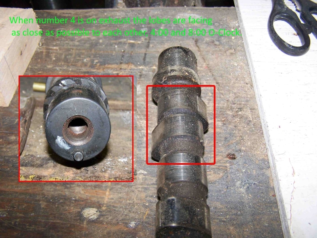 . | ||
Bill Vatter Experienced User Username: bill_vatter Post Number: 95 Registered: 09-2004 |
Jeff, Thank you, I believe I get it now. I have also read some on-line presentations that relate to cam timing and the effects of advanced and retarded timing. For clarity of understanding, I explain below what I now understand you to be stating. In this situation, the words I had difficulty understanding relate to the angle between the centerline of the cylinders and the centerline of the cam lobe. That relationship assumes the direction of tappet motion is the same as the direction of piston motion. This is the case for most engines with side positioned camshafts (not overhead camshaft) including those discussed here. "Exhaust and intake lobes pointing equally to each other" means these angles of the exhaust and intake lobes are equal. This is also termed "straight-up" timing. If the angle of the exhaust lobe is greater than the intake angle, the camshaft is considered "advanced" by 1/2 the degree difference of the two angles. "Retarded" timing is when the intake lobe angle is greater. Jeff, do we now understand the term the same? | ||
Jeff Martin New User Username: jeff_r_1 Post Number: 28 Registered: 07-2018 |
Yes, that's it. Not just engines with side mounted camshafts, but over head cams too. All this applies to my Jaguar as well. I believe it also applies to V engines as well, but the arrangement of the lobes will certainly be different from an inline cylinder engine. | ||
Patrick Lockyer. Grand Master Username: pat_lockyer Post Number: 2290 Registered: 09-2004 |
Still the same with quad cams. Takes me back to when I had a Jaguar mk1 2.4 and 3.4 Altered the cam timing, [not a lot] by the variation of cam sprocket not to factory spec, no power low revs but in a higher range the power came in and the cars became a flyers. | ||
Bill Vatter Experienced User Username: bill_vatter Post Number: 96 Registered: 09-2004 |
Jeff, Now that I understand the language, I can ask my technical questions: 1. How do you measure the angles referenced to determine when you have got the camshaft "straight up"? 2. How do you know RR intended the camshaft to be fit that way, neither advanced nor retarded from the straight up position, with both exhaust and intake lobes pointing equally towards each other? | ||
Patrick Lockyer. Grand Master Username: pat_lockyer Post Number: 2291 Registered: 09-2004 |
Don't waste your time, set the camshaft lobes as stated with piston number 1 at TDC use a dial gauge. keep it simple, not wanting to make a mountain out of mole hill, less time is less cost for the job. | ||
Jeff Martin New User Username: jeff_r_1 Post Number: 29 Registered: 07-2018 |
Hey Bill, 2 ways; look at the cam shaft and place it on your bench so the lobes for number 1 are at 4:00 and 8:00 O-Clock, when in that position the lobes for number 6 will be at 2:00 and 10:00 O-Clock. When the lobes are in these positions, the 4 bolt holes on the cam should be at 90 degree positions. This assumes that RR put the bolt holes at symmetrical positions to the lobes in the manner in which we are discussing here. To check this, after using the Rolls Royce method, remove the access panel on the BACK of the engine where the exhaust valves are adjusted. You will see the lifters for number 6 at equal positions. And that's one way to check it, either with Patrick's dial gauge or what I would do. When rebuilding an engine, use the exhaust and intake lifters to measure with. Get some rod the same size as the valve stem of the exhaust valve, this will allow the rod to fit nicely into the exhaust guide and sit on the adjusting nut of the lifter. Take another piece of the same rod and grind one end to fit into the intake lifter. Cut both rods so when seated into both lifters, the rods and lifters are of equal length as a whole. Note that the rod for the exhaust can be adjusted with the lifters nut to make both exactly the same length. Also make sure to cut the rods long enough so they will protrude above the block surface. The protruding rods can now be measured for equality, either with a depth gauge, or with a small straight edge that's parallel to the block. I suppose a level can be used, but the engine block itself would have to be level. A guide will also have to be cut for the rod that is in the intake lifter to keep it from moving side ways in order to get an accurate measurement. The cam shaft can now be rotated so the rods protruding from the block can be measured for equality. As far as RR changing the symmetry of the camshaft in relation to piston position, I don't know that for sure, but some laws of engine design can't be changed. I've never seen a cam shaft on an inline cylinder engine where the lobes are spaced differently other then what has been discussed here. The exception being a modern engine with variable valve timing. An example of an engine like that is the Mazda L engine. It's 4 cylinder twin cam and the intake valve camshaft can be changed on the fly by the computer, but only the intake camshaft. . | ||
Bill Vatter Experienced User Username: bill_vatter Post Number: 97 Registered: 09-2004 |
Hi agin Jeff. I have read and pondered your description of both your method and principles behind it. I conclude this will most likely not give the same lt as the factory method. Explanation follows: The definition of camshaft neither advanced nor retarded (or both exhaust and intake lobes pointed equally to each other) relates to the rotation of the cam between its position when the valve is exactly full open and its position when the piston is exactly at TDC. This amount of rotation is expressed as an angle, and when these angles for both the exhaust and intake valves are the same, the camshaft is considered to be positioned "straight up" or "with exhaust and intake lobes pointed equally to each other" when #6 piston is at TDC. or neither advanced nor retarded (several different ways of saying the same thing). These camshaft positions are difficult to accurately determine because when the camshaft is positioned with the valve exactly full open, valve train reciprocating motion is stopped, and for a very slight engine rotation in either direction, the valve train is moving so slowly relative to the both crankshaft and camshaft rotation that direct measurement of valve full open position is virtually impossible to achieve with the necessary accuracy. This is the same difficulty that makes direct measurement of when the piston is at TDC very inaccurate. Indirect methods giving accurate results for locating TDC are easy and straight forward, but perhaps not for a cam lobe. Note carefully, the angle relates to the centerline of the camshaft lobe and not to tappet height which is on the lobe flank in the method you describe. The method you describe could work if the cam lobes are exactly symetrical and if the exhaust and intake valve open durations are equal. However, this is NOT the case for any of the RR EPW camshafts (both in lobe symetry AND duration), nor is it the case for most other engines, vintage and modern. This situation is clearly observable from the data with drawings of cam lobe profiles posted by David Gore for Norman Geeson above on 3/25/2020. Modern engine builders are able to overcome these difficulties from the cam lobe data provided by camshaft manufacturers, and the use of a degree wheel for accurately measuring engine rotational positions. Cam lobe design data stating the rotational position of the lobe centerline may be in the archives somewhere, and if Norman is reading, perhaps he will know, or when social distancing restrictions are relaxed, he might be able to research the archives at Hunt House. Norman is clearly the best at that research. In the mean time, it would be very interesting to know how great the difference might be in the results obtained from the factory method and the method you propose, which for clarification are as follows: 1. (Factory method) Set the camshaft for #1 intake to just begin moving when the inlet rocker arm has been set for 0.030 inch clearance. 2. (Your method) Set the camshaft for the #6 exhaust and intake lobes equally pointed to each other when the engine is at #1 TDC inition using intake and exhaust tappets equally raised as the location determination. This would be relatively easily done by first setting the camshaft using method 2, and then checking the position using the factory method, observing the crankshaft position when #1 intake just begins to move. According to the factory, That should be with the timing indication pointing at the TDC mark on the flywheel for engines with camshaft RE23639, as I think you stated your has, or at some other position stated in the factory service instructions for other camshafts. Who ever does that would demonstrate the validity of your method, or refute it according to the results obtained. That would also be a significant service to the Club and all who seek to how to do it right with a good and valid method. | ||
Jeff Martin New User Username: jeff_r_1 Post Number: 30 Registered: 07-2018 |
I may just compare the two methods, I want to put a modern front crank seal on (if you want to know why I will start another thread) So to do that, I will have the whole front of the car apart. At that point it would be just another step to check and compare. When I timed my valve train some 20 years ago I used the method in the manual, only I used compressed air to let me know when the intake valve was open. It's only recently that I discovered the other method. I never liked the RR method, intake opens ??? By how much, 1 thou, just until the valve is off its seat, or just until the cam shaft makes contact with the lifter, it's not clear at all to me, the manual doesn't say at all ? If the manual would just say by how much the intake opens I don't think I would have problem with it. When I belonged to the RR club an air craft mechanic whom of which rebuilt a number of these engines said to rotate the push rod back and forth with your fingers until you feel resistance. I found that way to be very imprecise as well, assuming the lifter is well lubricated, I can't tell when there is, or is not enough resistance and what point the valve is sufficiently open, or open too much _ or not enough. The relatively week valve springs in these cars make turning the push rod to feel resistance not a good method IMO. However there is a way to check with out going to too much trouble, as stated above. Remove the back exhaust valve cover at the back of the engine. Turn the crank shaft to TDC when number one is on compression as close as it can be humanly possible. At the point both the intake and exhaust lifters should (will) be equal. Photo shows my car, they are not totally equal, but that may be due to the uneven casting of the block where the top of the lifters would be flush. It also may the fact that the intake and exhaust lifters are of different heights over all At any rate they are very close. The only way to be sure is to do the method that I described in my post. The car is at TDC as close as possible looking through a mirror at the access hole in the bell housing.  | ||
Jeff Martin New User Username: jeff_r_1 Post Number: 31 Registered: 07-2018 |
I can't edit my post anymore, so I have to start again. I am also going to disagree with you about my method not applying to modern engines. If you take a Jaguar for example, the cams are locked up with a plate that fits into a notch on each cam. And at this state the front piston is at TDC. This puts the lobes at the front exactly at 2:00 and 10:00 O-Clock. Jeff - No problem - I can edit it for you at any time. Just send me the text deletions and the text replacements you would like included either as a message through the forum [just click on my name to access my forum profile for a link to do this] or send an email to drh14434@yahoo.com.au and your wish will be my command!! | ||
Jeff Martin New User Username: jeff_r_1 Post Number: 32 Registered: 07-2018 |
Thanks David Bill, finally found a good video of what is happening with the valves. Should be no different with a RR engine, look where the valves are in relation to the piston. The other thing that would be interesting to do, is two compression tests with each method and see what produces the highest compression, I suppose in reality it shouldn't make a difference. https://www.youtube.com/watch?v=vg0x4_mQd9M | ||
Jeff Martin New User Username: jeff_r_1 Post Number: 33 Registered: 07-2018 |
Sorry, going on a bit here. Found the right words to put into Google. Here's a good article, and there are several, about what I'm talking about, and I will admit, that the cam can be put in different positions to change the scavenging effect and thus the running/idle of the engine. However, basically overall the cam lobes are at equal distance when number 6 piston is on exhaust and TDC. I think the RR method just gets the lobes a little for or aft to change the power curve and/or smooth running. I think both methods would work just fine. https://www.cartechbooks.com/techtips/camshafts1/ | ||
Norman Geeson Unregistered guest Posted From: 81.99.138.38 |
Jeff Before proceeding, earlier in this thread you mentioned:- �I'm also going to assume that the 4 or 8 bolt holes on the our cams will also symmetrically line up with the lobes so one can tell when the cam is in the correct position� That has never been the case with R-R post war six cylinder engines in fact the camshaft drawings say �Angular relationship of tapped holes and cams is not important� In connection with valve timing methods, to cut a long story short, the method you describe is known as �TDC rear valves on rock� Ideal for say 85% of engines. There are a few standout engine exceptions R-R six cylinder post war, Aston Martin 2.4 Ltr / 3 Ltr and for different reasons Jaguar XK being some. In addition a number of diesel and very large gas powered engines. Unfortunately the Aston Martin engine was designed by Bentley at Lagonda when he was having a bad day, on a good day the valves miss each other by 0.084 inch when cold. In connection with R-R engines I would seriously advise a full understanding of the effects of cam shapes and static valve timing with the R-R engine and specification. You will find the cam lobe positions very far out from being mirror imaged or near mirror image. From this fact alone you can be certain that it would be incorrect to use �TDC rear valves on rock� because you are bound to witness incorrect valve positioning at TDC, indeed it could not be otherwise. Ask yourself how you can achieve �TDC rear valves on rock� with these out of phase cams? Undoubtable you will achieve a running condition of some fashion, because there is no valve clash. I have run R-R engines on test deliberately with out of phase timing and at speeds below 50mph they are dead in the water and expensive and time consuming to rectify. I have also travelled half the World and more to find someone has set the valve timing incorrectly and ignored the maker�s instructions, and not just on R-R engines. It gets your attention when a Clark gas engine gets timed wrong you get excessive exhaust noise on start-up with petrol. That is because the outside silencer is in mid-air, having already passed through the ignition cabinet, oil cooler, radiators and air starting tank. It descends some yards away quite fast as it weighs more than a car. Moral�.follow the makers timing instructions It is beyond my pay grade to understand why anyone would not use the simple R-R timing method. These engines in particular have some unusual specification that tends to make them intolerant of valve timing errors. Consider the manufacture had the following points to address in choosing the cams and timing, and you are going to choose another valve timing method. At this point you must have therefore studied and understood the following six notes and fully realise the implications of being out a few degrees, not particularly a problem on a simpler specification. 1. An offset inlet rocker. 2 A radial crankshaft spring drive. 3. No direct coupling of the crankshaft pulley to the crankshaft. 4. An �F� head valve layout. 5. A variation between the static setting and running settings of the inlet valve opening and exhaust opening of 26 degrees and 19 degrees respectively. Similar variances apply for valve closure. 6 Very wide valve openings, the inlet valve is open for in excess of 300 crankshaft degrees. In respect of (6) above you are unlikely to ever see or work on another engine that has an inlet valve open for over 300 degrees of crankshaft rotation, and you can check all the Ferraris you like on that score. That fact alone should be shouting out that a few degrees on these R-R engines does matter. Due to the specification of the engine it is far away from mirror image cam positions and does not embrace �TDC rear valves on rock�. Yes I have compared R-R valve timing, (it is extremely simple) with �TDC rear valves on rock� and on EVERY popular post war R-R camshaft and they show clearly that the makers way is the route to follow. It may be of some interest that the �TDC rear valves on rock� method is useful to obtain initial rough settings on most engines. However valve fouling can be experienced on some engines if the engine is moved even a few degrees. Currently we have to agree to disagree on the R-R valve timing method, I have seen too many R-R engines with valve timing adrift, particularly in the USA to alter, and equally I have timed hundreds of other engines by using �TDC rear valves on rock�. (Message approved by david_gore) | ||
Jeff Martin New User Username: jeff_r_1 Post Number: 35 Registered: 07-2018 |
Thank you for taking the time to write that Norman. I won't disagree with you, but I will keep digging into this until I totally understand what's going on here. What I would really like to see is a 360 wheel showing when the valves are opening and closing exactly. That would give me some great understanding. And 300 degrees for the exhaust valve to be open, most of that would have to be when a given piston is just coming up on the intake stroke. Too much valve time open and the fuel air mixture will start to be pushed out of the intake manifold ??? | ||
Norman Geeson Unregistered guest Posted From: 81.99.138.38 |
Jeff You said "And 300 degrees for the EXHAUST valve to be open, most of that....." Note, I wrote ...." the INLET valve is open for in excess of 300 crankshaft degrees" Best to be talking of the same component from the start !! For the record the inlet valve does not finally close until 97� 30 degrees ABDC on engines with the RE 4550 inlet cams, and that means nearly all engines�..now that has set you thinking? I don�t know if you are aware that pistons travel further (and faster) in the first half of the stroke than in the second half! Whilst thinking about that, consider that the inlet valve springs also exert more cam force than they measure on a spring tester! Should you really be interested in keeping digging, as you say, I recommend you set out first to fully understand the operation of the crankshaft damper and radial spring drive starting with the articles in www.kda132.com . If you do not fully�� absolutely fully,� understand how this damper and spring drive work you will not understand the interaction with the camshaft timing. Just to keep you digging for some years ahead check out the interaction with the ignition distributer at the same time. As an exercise, when you have absorbed those articles, envisage what happens to the damper, spring drive and camshaft timing when going from full throttle to full retard at speed in gear. This was one of the subject issues we taught at Derby College to attendees from all dealerships, including the R-R ones. Interestingly we also had military pupils and the interaction of the R-R military dampers and camshafts we also taught. You have yourself at the start of some involved R-R detail possibly the most hard to fully understand. Time has shown some specialists have no idea of the component interactions themselves, and for sure ignore Mr Google and Mr You Tube, good as they can occasionally be. Starting with the damper and spring drive, study the detail and be very wary who and from which direction the details and claims are being presented. Never mind the dogs breakfast methods, or that every camshaft is ruined and worn, study the details and you will have a remarkably smooth running engine. When I have time I will dig out an R-R valve timing diagram and the engine BHP details. Meantime I will go outside and examine the chain drives on my 3.4 ltr XK <smile> (Message approved by david_gore) | ||
Patrick Lockyer. Grand Master Username: pat_lockyer Post Number: 2292 Registered: 09-2004 |
Don't you just like make it technical, keep it simple and do the cam timing static with the dial gauge. Make sure the cam lobes are positioned as stated early in the thread to confirm timing not 180% out. Job done, and a cost that can be a real treat. | ||
Christopher Carnley Unregistered guest Posted From: 86.182.152.186 |
The proper Rolls-Royce instructions are nice and proper with no room for the introduction of additional cumulative errors. These engines have been set like this for 100 years, without the "need" foolish introduction of the dial gauge. (Message approved by david_gore) | ||
Jeff Martin New User Username: jeff_r_1 Post Number: 36 Registered: 07-2018 |
Yes, I meant to say intake (INLET) Norman. Sorry I can't remember where I read this Norman, but maybe in the manual somewhere, that the damper moves so very little to dampen out the torsional vibrations of the crank, it does not effect the valve timing, or the ignition timing for that matter. At least when I use a timing light for the ignition, it's pretty much rock steady flash on TDC. That assumes that the damper is set up properly as to the instructions in the manual. I can imagine a damper with not enough load on the tension springs and it moving around more then it is allowed to. I guess in a state like that it wouldn't do it's job either. Plus I would also assume that the uneven load that the cam shaft puts on the drive gear would move the damper all over the place with in its limits _ and of course the ignition timing would be very erratic as well. Also, yes I am aware that the piston travels faster at certain positions in its revolutions, but I was not aware it travels further. A valve timing diagram would much appreciated, the one for the 4.25 in the manual is a little vague and confusing. Christopher, I think a dial gauge would come in very handy to find just when intake opens. Better then working the push rod back and forth with ones fingers. | ||
Norman Geeson Unregistered guest Posted From: 81.99.138.38 |
Jeff I promised that I would dig out a R-R post war six valve timing diagram for you as soon as I could access my notes. I trust the information is what you needed. I have listed the Silver Cloud 1 / Bentley S1 valve timing, which in this particular case has identical cams and timing to the late Bentley MKVI / Bentley R type. The listing shows valve opening and closing in running trim. Inlet Opens 26 degrees BTDC Inlet Closes 97 degrees ABDC Exhaust Opens 61 degrees BBDC Exhaust Closes 24 degrees ATDC (Message approved by david_gore) | ||
Jeff Martin Experienced User Username: jeff_r_1 Post Number: 63 Registered: 07-2018 |
Thanks Norman, just saw this. I haven't put this to bed yet, I've just been too busy doing a bunch of fixes on the Bentley. The compression is at 115 PSI so the cam must be in a fairly good position. Although some report 120 PSI so there may be room for improvement. Big job to delve into it... One of these days I would like to get some domed customs pistons made to raise the compression to at least 120 to 140 psi, in an attempt to evacuate the exhaust more efficiently. This should also help to get a better burn. I'm not an engineer, but from my understanding of how an internal combustion engine works, it should improve things. | ||
Christopher Carnley Unregistered guest Posted From: 86.128.179.246 |
You cannot fit domed pistons or any with any lozenges on top. The inlet valve travel is quite considerable, and the piston almost strikes the face of the head. Compression was raised by slicing off a bit of the head face and fitting a thin corrugated gasket. This was also done to the S1 head to raise the compression. Your best bet is to scrap the exhaust system and fit two Jaguar boxes, if on twin pipes. The MK VI system absorbs 28 BHP and the fan another 5 Chesman Engineering make an S1 head that is up to 8.8:1 CR. (Message approved by david_gore) |