| Author | Message | ||
Brian Vogel Grand Master Username: guyslp Post Number: 1523 Registered: 6-2009 |
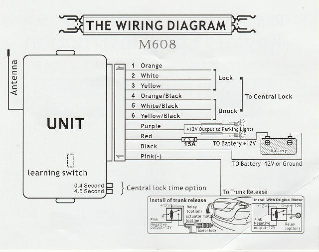
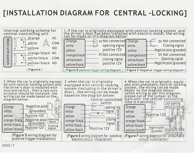
Due to a disintegrating power window guide I have had to open up my driver's side door to fix it. I have wanted to install keyless entry and long ago purchased two units, one for this car and one for the SW-II. Since the door panel is now off now would seem to be the ideal time to put this thing in. I need assistance to double-check if my understanding of the Cadillac wiring diagram for the door lock system and the keyless entry unit and signal setup are correct. Here is a 2-page PDF scan of the wiring diagram for the car's power door lock system. The wiring diagram for hooking up the keyless entry transponder unit:  The hook-up wiring for the actual lock/unlock signaling:  If I am reading things correctly, this is how I plan to proceed. 1. The orange wire on the car that is used for the door lock/unlock switch is an always hot +12V source. Based on the transponder unit wiring diagram above, I would splice the the following three wires to this orange wire on the car:
Since the orange wire is fused on the car at 20A and the unit itself is fused at 15A I would think that this arrangement would be OK. 2. I would splice the white wire from the transponder to the light blue wire on the car's lock/unlock switch. 3. I would splice the white/blk wire from the transponder to the black wire on the car's lock/unlock switch. I am planning on keeping the signal timing to the 0.4 second setting at least to see if that will work. It may be a hair too brief, but the 4.5 second option seems like an eternity to keep the electricity flowing for a door lock. Am I missing something, or do I have this correct by some miracle on the first shot? If I have this may give me the confidence to figure out how the lock/unlock is wired on the SW-II and put that project on the list. I am only interested in the keyless entry option at the moment, so won't be hooking up the connections to make the parking lights flash or the trunk release function (which it doesn't do when the car is not running anyway, which seems somewhat backwards to me). Brian | ||
Robert Noel Reddington Grand Master Username: bob_uk Post Number: 309 Registered: 5-2015 |
4.5 seconds shouldn't burn out the dood locking motors or solenoids. Recently I helped wire in a keyless entry system into a Lotus Elan. No door handles body shaved. I followed the instructions and it works fine. This system unlocks the door and a plunger pushes the door open about 2 inched. Once I had tested it I made proper wiring looms. The ecu operates relays which in turn operate the door lock solenoid and the plunger to push the door open a bit. The relays 2 in each door are mounted in the doors. Two fat wires brown for 12v and black for earth. Lucas system colour code. And two much thinner wires for the signals from the ecu. Red is lock and yellow is unlock plus plunger. The plunger doesn't fire on the lock or red signal. Plus twin speaker wire. 6 wires in total. The reason for putting the relays in the doors was to keep voltage drop to a minimum. Hence fat wires as well. Also it minimises the number of wires going through the door hinge area. Glass fibre car so no reliable earth unless run separately. The system you have is similar to the one I wired in except the colours are different and I used relays between the ecu and the locking solenoids. The hardest job was the fitting of the locking solenoids which someone else did. Actually wiring it was easy except the hinge area. Gommett problems. Glass fibre is thicker than metal. Plus the Elan is in mock up stage so its all got to come out again for painting. | ||
Geoff Wootton Grand Master Username: dounraey Post Number: 848 Registered: 5-2012 |
Hi Brian That is the way I configured my SY1. It is just a simple switch, so if you have 12v on the yellow or yellow/black, the 12v is simply switched through to the white - white/black respectively. Just a case of getting the wiring the right way round to fire the solenoid, lock/unlock. I was a bit concerned about the wires being too small gauge and considered putting a relay in, but in the event, powered the solenoids direct at 0.4 sec. So far, it has worked fine. You can also switch an earth connection through, if the Cadillac is wired differently. Congratulations on making sense of the instructions. Geoff | ||
Brian Vogel Grand Master Username: guyslp Post Number: 1525 Registered: 6-2009 |
Bob, I can see no reason that I would need to run any wires through the door hinge conduit since all wires I've noted are readily accessible in the door itself. There is also a ground/earth wire for both the power windows and power seats. There may be a third for the power mirrors, but I didn't bother to check that. I could also use the "hot at all times" +12V source from the power seats rather than the locks as the input for the unit itself (though probably not the lock/unlock +12V) since the wiring is much heavier. Since the lock switch in the door controls a relay I can't see how this wouldn't be a direct "splice and play" based on how the system is set up. All of the door switches are used to trip relays, so no additional relay should be necessary "upstream" of the relays they trip. Brian | ||
Brian Vogel Grand Master Username: guyslp Post Number: 1526 Registered: 6-2009 |
Geoff, Thanks for the vote of confidence. Based upon Bob's input I did go back and confirm that I have existing earth/ground wire already in the door. I only wish I could find a perfect location where this unit could be placed so that I could get the light blink going and rewire the trunk release so that it would be live at any time, not just when the car is running or still in retained power mode. I will be thrilled if I can get the doors to lock and unlock using a key fob. Brian P.S. Did you have to do anything to get the transponder to recognize the fobs? There's nothing that indicates this is necessary, but the instructions aren't the greatest. | ||
Geoff Wootton Grand Master Username: dounraey Post Number: 849 Registered: 5-2012 |
Hi Brian Regards the Rolls, make sure you use the correct ground wire. It runs back to the power windows disable switch on the drivers door. If you use a local ground, you will lose this functionality. This of course assumes the SY2 is wired similarly to the SY1. The transponder was already set up to recognize the fobs. Incidentally, I have found the fobs are not very resistant to a full cycle in the washing machine. Geoff | ||
Brian Vogel Grand Master Username: guyslp Post Number: 1528 Registered: 6-2009 |
Geoff, With regard to the fobs (or anything electronic, for that matter) these things will often survive laundering, dropping in water, etc., if you promptly take them apart (within reason) and allow them to dry thoroughly before putting the batteries back in. I've told people who had keyboards that are getting flaky, or that they've spilled a Coke in, to run them through the shower or a rinse only cycle in the dishwasher then let them dry for a day or so and give them a try. Most often they're good as new. When PDAs (remember those?) were new, and I was working as a cognitive rehab therapist in a brain injury program, I had several clients drop theirs in "bodies of water" over time. I revived all but one by opening them up and letting everything dry out before trying to fire them up again. Corrosion from retained water or retained water itself are the cause of most failures. Though I didn't manage to get the door put back together I did get the transponder wired and was able to test the fob. The only weirdness is that their own wiring instructions reverse the functions of the lock and unlock buttons. It's no problem to finish the hook-up by reversing them, though. Brian | ||
Geoff Wootton Grand Master Username: dounraey Post Number: 850 Registered: 5-2012 |
Hi Brian It was a while ago now, so I suspect I have left it too late. My mistake was to not open it up and remove the battery. I was hoping the thing might just come back to life, but it didn't. I have not paid it any attention since, as the other fob works fine. I might just check it out this weekend and see if I can get it to work with a clean and a new battery. I'll remember your advice for any future mishaps. Geoff | ||
Brian Vogel Grand Master Username: guyslp Post Number: 1529 Registered: 6-2009 |
Thanks to Bob & Geoff for their responses. The installation is complete and the key fobs are working flawlessly and from a far greater distance than the OEM ones on my other cars have done. Last night a private response expressed confusion at the lock/unlock power source wire arrangement I listed. To me open/unlock are synonymous as are close/lock. However, the unit wiring diagram is correct in that when you press the lock button the signal for that comes over what the installation diagram shows as "open signal" and vice versa. It was simple enough to figure out, though. If anyone is interested in an inexpensive aftermarket system with really high quality fobs (far better than any that have come with any car I've owned, including the Jag) these are available for a song from Amazon. The brand name the seller is using for these keyless entry systems has changed several times but those I've known who've ordered them have all received the same item in a box labeled Bighawks Keyless Entry System with features and fobs exactly as described and pictured. The fobs are mostly of metal construction and could be used as weapons if tied to the end of a string and swung hard. Brian | ||
Geoff Wootton Grand Master Username: dounraey Post Number: 853 Registered: 5-2012 |
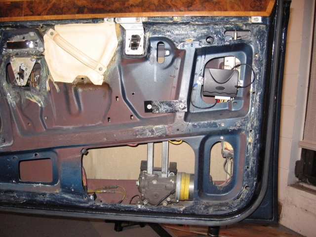
I bought exactly the same. It has worked fine. I was a bit concerned the light gauge wires would not be up to driving the solenoids direct, but have had no problems with this. As Brian says, the fobs are very robustly made. I did wonder if the weight might put a drag on the ignition switch, but I doubt it. It is only slightly heavier than the fobs I am used to. When I fitted mine, I followed Paul Yorke's advice and used the passenger door. There is less wiring to get in the way. The longest part of the installation was making two brackets to attach the unit to the door. The rest was simple. Wiring in the boot lock and lights would however have made the job more involved because of the extra wiring that would have been required. Great system though for less than 20 bucks.  | ||
Brian Vogel Grand Master Username: guyslp Post Number: 1530 Registered: 6-2009 |
Geoff, Brackets?!! God created cable ties for a reason! Brian |