| Author | Message | ||
Christian S. Hansen Grand Master Username: enquiring_mind Post Number: 620 Registered: 4-2015 |
The vaccuum pots with internal diaphragms (Part # UD1222) that control the heater and demister water taps found on my Cloud I and many other EPW models are not holding vaccuum probably due to cracked rubber internals. Replacements are pricey @ $400US+. While they do not look to be rebuildable, has anyone tried? Any possible workarounds? . | ||
Jim Walters Prolific User Username: jim_walters Post Number: 126 Registered: 1-2014 |
Christian, it is something I have thought of doing however I am so overwhelmed with work that I will not be able to pursue it any time soon. I have figured out how to do it, but need to make up jigs before I can attempt it. Basically it would involve making up a holder that fits each half of the pot with an open area where the bent over lip is. The lip would be peeled back to separate the two halves, probably would have to anneal it first. Insert the new diaphragm, then clamp the halves together in the jig in the lathe. Using metal spinning techniques, form the lip back over to hold the halves together. That is how it would be done, but I don't anticipate having the time to do it until perhaps next spring the way things are going. In the meantime, I am looking for core vacuum pots so if anyone has dud ones they want to donate I would be interested in obtaining them. SRH8505 SRC18015 SRE22493 NAC-05370 www.bristolmotors.com | ||
Christian S. Hansen Grand Master Username: enquiring_mind Post Number: 621 Registered: 4-2015 |
Jim... Thanks for reply. This presupposes that replacement diaphrams are available or can be made. One pot will not hold vacuum (bad diaphragm), the other holds vacuum but seems to be leaking coolant from bottom half (under diaphragm) which should be impossible as there should not be any coolant in the pot. The coolant should not get past the diaphragm in the lower flow control section. There are no schematics showing this arrangement that I am aware of so will need to draw something up if unclear to others not familiar with the internals of the vacuum operated heater and demister tap design. Any ideas how coolant can get into the upper vaccuum chamber? . | ||
Jim Walters Prolific User Username: jim_walters Post Number: 127 Registered: 1-2014 |
As it happens I am rebuilding two of them at the moment. Coolant is entering the vacuum chamber because the diaphragm seal in the water valve is shot. 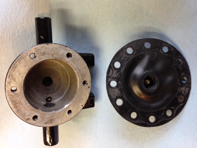 Water valve and seal which controls coolant flow. 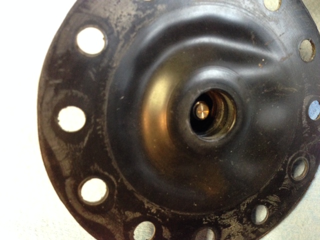 The threaded brass bit in the middle threads into the vacuum pot. 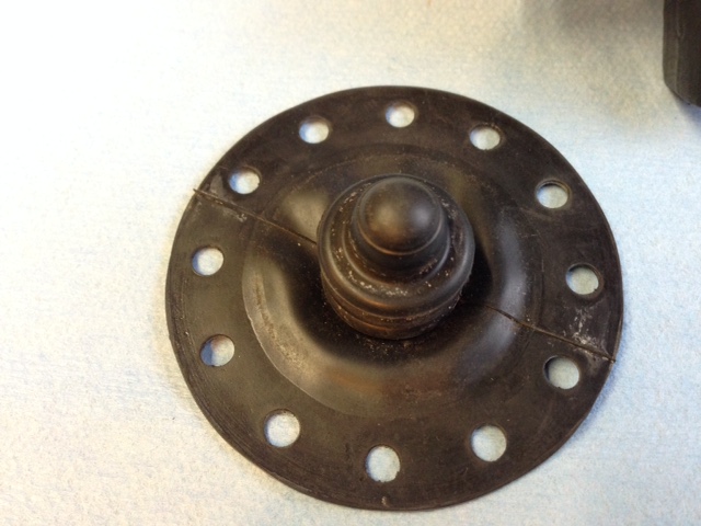 The bit in the middle is moved up and down by the vacuum pot to open and close the water port seen in the middle of the water valve housing in the first pic. SRH8505 SRC18015 SRE22493 NAC-05370 www.bristolmotors.com | ||
Christian S. Hansen Grand Master Username: enquiring_mind Post Number: 622 Registered: 4-2015 |
Image I: 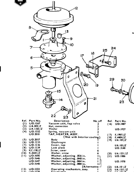 Image II: 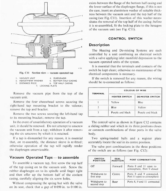 Jim... Great photos and they confirm what I managed to speculate. Defective diaphragm. But also precipitate a further consideration. I fussed around and found the above images. The first from parts manual, but under "electrical" Section L, where you would not expect it to be(!) and the second in the service manual under Air Conditioning section. Note that in the parts diagram and parts list there is a variable thickness aluminum adjusting washer between the vacuum pot and the tap body (#11). Rhetorical question is: How critical have you found this adjustment to be? Since it is an EPW Roll-Royce where they always had a reason for doing what they did, I venture the answer is "yes". Here is the long story of why I ask: The heater tap on the Cloud I (1959 LSMH109) seemed to always be in "hot" position (block tap in "Winter" position). The first position of the dash pull knob opens the air flap to get ambient temperature external air. The second position opens the heater tap. Presumption was that the tap was defective and was not sealing properly when in "off" position, i.e. first pull position. Proposed solution was to replace the lower tap diaphragm. Upon removal, it looked just like the one in your photos...showing an indentation where the bulb end had been repeatedly pressed into the opening at bottom of tap, thus not sealing properly and allowing hot coolant to pass thru the tap body. We then found that the upper vacuum pot was not functioning either (did not hold vaccuum) and installed a used spare that did hold vacuum. Upon installation into the Cloud, it was found that coolant dripped from the upper vacuum chamber and exited thru a bleed hole. The ONLY way coolant can get into the upper chamber is if the lower diaphragm is defective, but it had just been replaced. Clearly SOMETHING ELSE is in play. Today, after removal, disassembly, and inspection, we found that the sealing witness marks on the new diaphragm were suspicious. Whereas the old diaphragm as well as the one in your photos have a clearly defined circular impression at the edge of the mating edges of the two halves, the new diaphragm did not. I will try to get a photo tomorrow, or at least draw a representative illustration. Here is my suspicion: If the "throw" or travel distance of the vacuum activated center shaft is too much, is it possible that the diaphragm is being distorted and pulled inwards such that the extra holes in the diaphragm extend into the center chamber and thus allow coolant to bypass the diaphragm? I realize that I may not be expressing this correctly and will attempt to take photos tomorrow. The point is that the parts diagram shows "adjustment" washers and there must be a reason. Also note that the assembly instructions clearly advise that a certain distance that is influenced by the choice of washers is critical to within .050 to .100 inches. They also note that failure to install the distance stop piece (#13) will "rapidly render the diaphragm unserviceable". So...I suspect that this distance is critical as it affects the rod travel and thus stress on the diaphragm and was different between the two vacuum chambers, and that as a result the extra travel is pulling on and distorting the diaphragm and thus creating a bypass route for the coolant. I can seen no other reason why a brand new diaphragm should be defective and allow coolant to bypass. Your thoughts?? . |