| Author | Message | ||
Brian Vogel Grand Master Username: guyslp Post Number: 2171 Registered: 6-2009 |
Hello All, I am hopeful that this may be the year that I get back to work on LRK37110. For the last 2 years (give or take) she has been immobile since her distributor was transplanted in to SRH33576. I have a brand new Mallory distributor that was made specifically for the RR V8 (Thank You Kelly Opfar!) and had the part of the distributor that mates with the drive transplanted to the Mallory, so that will be going in. I've kept the original Lucas distributor, which some future custodian can put back in along with a new module if they so desire. Before all this, it appeared that the timing was grossly off. She would idle and rev fine at rest, but try getting her to move, particularly up a grade, and there was no power whatsoever. I will have to check out the carbs, too and will be using Kelly's kit to balance them. Once the car will start again, I'm really not sure whether it makes sense to try to balance the carbs or adjust/perfect the timing first, or if something else related to the ignition needs to be addressed (other than reinstalling the distributor) prior to either of those two. Advice on the progression would be appreciated. On a related note, if anyone knows what the wires are that go in to the connectors A, B, & D on this image please share: 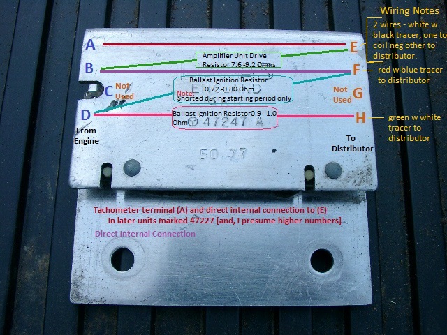 Brian | ||
David Towers Frequent User Username: xtriple Post Number: 79 Registered: 6-2010 |
I believe that ignition/timing side of things should always be done before any fuelling adjustments are attempted. Well, that was what I was taught back in the dim and distant past when cars had point/condensers and timing that could be adjusted! | ||
Geoff Wootton Grand Master Username: dounraey Post Number: 1529 Registered: 5-2012 |
With an engine I am not familiar with e.g. newly purchased car, my method is to remove all the plugs and check the compression first. This will give an indication of the condition of the engine and expose any major problems with the valves. Then I set the ignition timing and finally the carbs. Then round-robin fashion - ignition, carbs until no further adjustments need to be made. It's relatively cheap to replace all the ignition components so they are worth changing if you are not sure of their condition - plugs, leads, distributor cap, coil and points + condenser (where applicable) Geoff | ||
Larry Kavanagh Experienced User Username: shadow_11 Post Number: 27 Registered: 5-2016 |
Can't help with your wiring question but with regard to your engines power loss it's possible that the coil wires are the connected wrongly, came across similar symptoms in another post recently and coil ground was connected to pos while pos was connected to ground, car started and idled fine but had little power on acceleration and backfired. | ||
ross kowalski Prolific User Username: cdfpw Post Number: 244 Registered: 11-2015 |
Brian, The list of possible causes for that symptom is pretty big. Be sure to confirm TDC mechanically when setting the timing as the harmonic balancer might have slipped and the indicated marks could be off. Just had the balancer on the jag slip so bad it couldn't drive the alternator. | ||
John Beech Prolific User Username: jbeech Post Number: 146 Registered: 10-2016 |
Brian wrote in part . . . "Before all this, it appeared that the timing was grossly off. She would idle and rev fine at rest, but try getting her to move, particularly up a grade, and there was no power whatsoever." Let me share my experience with the EXACT same symptoms, e.g. an engine that would instantly start, go vroom-vroom nicely in park or neutral, but couldn't accelerate the car worth beans, and how I resolved it! Turns out the coil wires were reversed. Thus, instead of the wire to the distributor coming off the negative side of the coil (the ballast feeds the + side), some joker had reversed them. Interestingly, this still allows a current from the battery to build up in the primary-winding of the ignition coil, but the end result is insufficient juice to properly energize the secondary-winding (e.g. enough to fire the the plugs under load). Note, when the coil itself goes bad it won't go vroom-vroom at all so this is a rather mean trick to sort out because it's not how either a coil or a capacitor (condenser) fails. Anyway, these were the symptoms presented when I went to drive Tootsie (before purchase) and I figure the joker was a previous lookie-lou, e.g. some time-waster who didn't buy the car. And FWIW, the seller told me about a guy who returned three times to drive her and each time after driving the car, wanted to spend time looking under the hood (and of course, switching the wires is the work of but an instant). Why on Earth would someone do this? Perhaps he did it so when the next guy came to look and drive he'd have a bad experience and thus, pass on the purchase in hopes (and this is my theory) this would allow him to subsequently negotiate a better price . . . but who really knows what motivates some people? Regardless, there's no question in my mind this was done intentionally. By the way, this was the same guy who made an offer that was accepted but then got furious when she made a minor transposition error in the paperwork for recording the automobile's mileage and stormed off after throwing a hissy-fit. After that experience she resolved not to let anyone else drive the car and I was the next person to come see it. Thing is, the car was represented to me as a 'driver' and in America that has a specific connotation of a vehicle you can hop in and drive and doesn't need anything the seller hasn't disclosed. Anyway, when we arrived from Orlando (a +3-hour journey) and learned this, I turned on my heel and began getting back into the truck. Sensing I was serious she relented and the rest is history. Why would I take a chance there wasn't something seriously wrong? Simply because a) the seller would have no reason to do something like this, b) said seller was clearly perplexed as to why the car wouldn't run as advertised, c) the coil wasn't new, d) the maintenance records didn't show it as having been done in the recent past, e) I spoke to the shop and the mechanic who had been maintaining the car for the previous 8 years and he assured me the car ran nicely (they're an hour away and fetched the car from her home using a flatbed every 2-years for maintenance - oil change and filter, grease, balance and rotate tires, plus a front end alignment despite the car never accumulating more than 80-120 miles in the intervening interval), and f) the seller said (and I believed her) that two previous lookers (including the asshat who threw a fit) had driven the car without complaint. However, we couldn't get the car to develop enough power to return all the way home, e.g. climb the shallow incline of her driveway and into the garage and thus, we resorted to pushing the car the final 50 feet (and that car is damned heavy). Anyway, I took a chance on the purchase figuring it had to be something minor (I suspected bad gas), which I could subsequently resolve at my leisure. However, as it turned out, this problem perplexed me and I farted away a week on it before resolving it. Why? Simply because it never occurred to me to check the leads on the coil. Once I did, merely reversing them rectified the problem and presto, Tootsie ran (runs) just fine! Folks, regardless of automotive brand, the way a point-type (negative ground) automobile ignition works is . . . Battery --> Switch --> Ballast Resistor --> (+)Coil --> (-)Coil --> Distributor Last thing, first, some ignitions work with a coil that has internal resistance instead of a ballast resistor - but otherwise - the sequence is exactly the same. Second, if equipped, a tachometer wire (often green) connects to the negative side of the coil. Anyway, I hope this story is of some help for the next guy who is presented with these symptoms. I know I would happily throttle whomever wasted my time in sorting this out. | ||
Patrick Lockyer. Grand Master Username: pat_lockyer Post Number: 1069 Registered: 9-2004 |
Brian, forget points condenser, you have the Opus system. To cut the chase A-B-C as you put it TACO- +SW- START. I have put the above in detail on this forum in the past. Due to the length of time and with possible cylinder wash [petrol] the first test would be a cylinder leakage test. | ||
ross kowalski Prolific User Username: cdfpw Post Number: 245 Registered: 11-2015 |
Brian, It's not too late to fit points. When I bought my car the guy said he couldn't get it to fire. He had already attempted to start the engine so I asked him to turn it over. The compression sounded good so I bought it. Clean fuel from a random gas tank plumbed to the carbs and a few minutes with a test light and point file( don't use point files) Pop goes the engine. Anyway, if you pulled / towed that engine into my driveway and hadn't run in two years here's what I would do.Throw a quart of MMO in along with some STP, then compression test on all 8, plug inspection, spark existance check, maybe a lot of electrical tests if no spark, plug wires location and resistance check, timing, spray to life with carb cleaner, pull the main fuel line flow test, pull bowl covers flush and check needle valves and inlet filters, either pull carb bell or use slide lift buttons to confirm slide movement. If you have the tools readily avilable that should be an hour or so. Then when it was running I would throw on a vacuum gauge. A vacuum gauge will tell you in a seconds all sorts of useful things like " mouse nest in exhaust" etc. Good gremlin hunting in the new year. | ||
Brian Vogel Grand Master Username: guyslp Post Number: 2172 Registered: 6-2009 |
Patrick, While I know what the A, B, & D connections are *supposed* to be for since my cars don't have a tachometer I'm trying to figure out what the wire that connects to terminal A actually goes to. If you know please share. More generally: The car was compression tested when I started working on it in 2013 and I really have very little reason to believe that anything has changed - it was fine. I will definitely check the coil connections though at this point I have no way of knowing whether they were incorrect before or not. LRK37110 served as the "donor car" during the lengthy diagnostics after the Christmas 2014 FTP of SRH33576, including coil transplant (which was reversed) and distributor transplant. All of the spark testing, etc., was done a couple of years ago, too, and all was well. Essentially the first order of business will be getting her to start an run again. All else will follow from that. As I am not a stickler for originality, prefer an electronic ignition to points, and know the reputation that the Mallory optical ignition system I am more than happy to use that distributor. I've also had the coupling transplanted from the Lucas distributor that had the failed module to this distributor. It would be my fondest wish that the issue I was having might have been secondary to someone having stupidly reversed the wires to the coil. This car was one-owner before me, and carefully maintained by a dealer until he fell ill, after that it's clear that some "helpful relatives" or similar got hold of the car and did things like cutting the main wire to the ammeter shunt and a couple of other things that defied explanation. Thank heaven these were few and easily identified issues. They might easily have screwed up the wiring to the coil at some point and this is something I definitely had not checked. Since I know what works on SRH33576 I am imagining the exact same wiring arrangement will be used on LRK37110. We shall see when spring arrives and I can get her pushed back out of the garage. Brian | ||
Brian Vogel Grand Master Username: guyslp Post Number: 2173 Registered: 6-2009 |
Now, moving right along with installing the new Mallory Distributor I need some additional advice. The instructions given are as follows: ------------------------------------- Wiring Procedure The three wires coming from the UNILITE� Distributor must be connected using the distributor wire harness furnished (see Figures 1 and 2). RED WIRE: If you use loom resistance wire connect to the coil (-) terminal If you use a ballast resistor, connect to 12 volt side of ballast resistor. GREEN WIRE: Connect to the coil (-) terminal. BROWN WIRE: Connect to engine block ground. Clean away any grease, oil and paint from the mounting surface before the connection is made. ------------------------------------- Here is Figure 1 (which is the one that applies since we do have a ballast resistor): 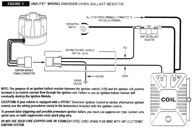 And here is an updated ballast resistor block photo with annotations since Patrick has confirmed what I thought I knew about terminals B and D (C is not used and there is no wire that goes to it, nor its opposite side companion, G), and I corrected my annotation for terminal H: 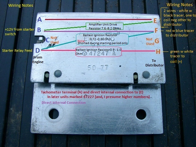 ------------------------------------------------- Since we don't have a simple ballast resistor here I want to be absolutely certain about where I hook up the red wire. It seems to me that because we have a straight through connection from the +12V ignition switch from B to F [the "shorted during starting connection] but also the ballasted feed from the starter relay which continues while the car is running that terminal F is the logical connection for the RED WIRE. The GREEN WIRE would be connected to coil(-) per the instructions and the BROWN wire run to ground/earth. For those that understand wiring diagrams, and this darned ballast resistor block (as opposed to a plain ballast resistor in the older cars) do these wiring arrangements to the 9BR ballast resistor block appear to be correct? Brian | ||
Brian Vogel Grand Master Username: guyslp Post Number: 2174 Registered: 6-2009 |
Also, for a full diagram of the 9BR as things are connected in SRH33576, which is easiest to read if printed on a letter sized sheet of paper, click here to download. Brian | ||
michael vass Prolific User Username: mikebentleyturbo2 Post Number: 255 Registered: 7-2015 |
Hi Brian I've had a look at this and my take would be :- H to coil+ F to red dizzy loom the rest should be as in the unilite diagram ok hope that helps Mike | ||
David Gore Moderator Username: david_gore Post Number: 2367 Registered: 4-2003 |
For anyone who has little or no experience of using a vacuum gauge for diagnosing engine problems, the interactive display on the following link shows you an actual display of various gauge indications and gives the probable cause for follow-up investigation. Just click each scenario button and all will be revealed: http://www.secondchancegarage.com/public/186.cfm Hope this is useful................ | ||
John Beech Prolific User Username: jbeech Post Number: 148 Registered: 10-2016 |
Superb, David, truly superb. It's been years since I've reviewed vacuum gauge use and this refresher is outstanding. Well done! | ||
Geoff Wootton Grand Master Username: dounraey Post Number: 1538 Registered: 5-2012 |
Great find David. This is something new to me and certainly something I will pursue. Seems to me the best take off point will be the vacuum tube to the bellows. Geoff | ||
Brian Vogel Grand Master Username: guyslp Post Number: 2175 Registered: 6-2009 |
Michael, Thanks. I had intended to connect in the following way from the "distributor side" of the 9BR: 1. Keep the output from terminal H going to coil(+) as it always has 2. Hook Mallory harness GREEN to coil(-) and also have another connection between it and terminal E 3. Hook Mallory harness RED to terminal F 4. Hook Mallory harness BROWN to ground/earth As it happens the wires that come out of the female ignition module connector are simply continuations of their respective colors on the harness, which is no surprise, really. This configuration means that I also do not need to do anything on the end of the Mallory harness for the RED and GREEN wires except put on an insulated female slide connector and a ring connector or spade connector on the BROWN wire. Also, there is no need to mess with the 4-slot connector used on the original Lucas distributor at all. It can remain exactly as is so that the Lucas module can be rebuilt or replaced by a Pertronix or similar. It sounds like the plan I had in mind matches what you do as well. If anyone sees something that we have not, please speak up. Even if you concur, having multiple concurrences makes me feel better anyway. Brian P.S. to David Gore: Thanks for your addition to the discussion, too. That's what I love about this place!! | ||
Patrick Lockyer. Grand Master Username: pat_lockyer Post Number: 1070 Registered: 9-2004 |
Well that was a hum dinger new year party! Brian unless I see it wrong you are going to run two ballast resisters in the setup. The terminal E is one of the wires for the amplifier-pickup 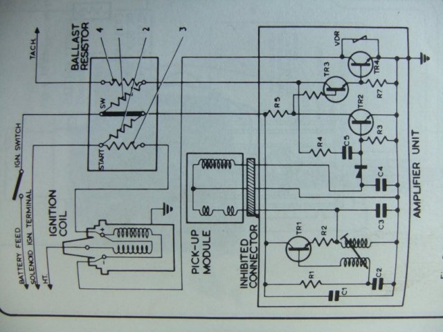 | ||
Brian Vogel Grand Master Username: guyslp Post Number: 2176 Registered: 6-2009 |
Patrick, I suggest you look at how the diagram you supplied maps on to the 9BR and how the wiring I showed from SRH33576 connects to the 9BR. You are correct that what I note as terminal E is one of the terminals from/to the amplifier as shown in your diagram. In your diagram, it also has a resistor across it, which is absent in the later 9BR. Terminal F, based on the actual 9BR diagram, appears to be the central terminal on your diagram which shows the one and only "straight through" connection on yours. It also connects directly to the amplifier unit. Here are the two diagrams side-by-side: 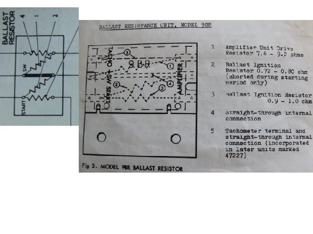 The 9BR diagram has the middle of the three connections (the one matching SW on both diagrams) marked as "AMPLIFIER" and that matches how it's actually hooked up with the Lucas unit. Your own diagram shows one of the two connections to the amplifier coming from that terminal. I'm unpersuaded that terminal E in my 9BR diagram would be correct for the Mallory RED wire. You'll have to do more to persuade me. It also seems that I am routing the Mallory GREEN wire to terminal E via a shared connection at coil (-) rather than running the two wires into a single connection at terminal E as was done with the Lucas setup, which achieves the same result with regard to the TACHO connection. Brian | ||
John Beech Prolific User Username: jbeech Post Number: 149 Registered: 10-2016 |
Brian, Let's go back to square one. Drop the RR distributor back into the engine, check the coil wiring, and start the car. After you have it running, R&R the distributor in favor of the Mallory. | ||
Brian Vogel Grand Master Username: guyslp Post Number: 2177 Registered: 6-2009 |
John, No. I have one functioning RR distributor and the Mallory, with drive coupling transplanted. I have no intention of rebuilding the other Lucas distributor at this time. Brian | ||
ross kowalski Prolific User Username: cdfpw Post Number: 249 Registered: 11-2015 |
Brian, I think Michael is correct with "H" to the distributor + red wire and "F" to the coil +. The mallory wants straight 12v to run whatever electronics it has on a red wire going to it. Put a volt meter ( often reffered to as a VOM for volt/ohm/meter) on the "F" terminal and ground. With the key off - no voltage, with the key in the run position - 12v, and with the key in the crank position ,- 12v. If "F" does that logic, use it to power the mallory on the red wire. The "H" terminal should supply something less than 12v in the run position and probably crank ( not that it needs to do anything in crank), and should read nothing with the key off. If "F" does that logic with some voltage less than 12v hook it up to the + side of the coil. There needs to be some way of getting full 12v to the coil on crank. Most engines have a wire from the starter relay or solenoid, I don't know how RR manages that part but it will be a line on the wiring diagram. Make sure there is a supply of 12v to the coil on crank. If you are not sure, check it with the VOM before hooking it up to the + side of the coil. | ||
Brian Vogel Grand Master Username: guyslp Post Number: 2178 Registered: 6-2009 |
Ross, You've reversed what Michael (and I) have said. Terminal F - Mallory RED to Distributor Terminal H - Coil (+) The +12V in crank/start is provided via the ignition switch in the START position, which completes the Terminal B to Terminal F "straight through" connection. The reduced voltage once the ignition switch is in the RUN position and the straight through connection from Terminal B to Terminal F is no longer being completed by the ignition switch. Brian | ||
ross kowalski Prolific User Username: cdfpw Post Number: 252 Registered: 11-2015 |
Brian, Oops, mistyped that. I think michael is correct that "F" goes to the Mallory unit and "H" goes to the coil. Also that "E" might not need to be wired to the coil + with the mallory setup. | ||
Brian Vogel Grand Master Username: guyslp Post Number: 2179 Registered: 6-2009 |
Ross, Oops again, in that the connector to terminal E shared two wires, one from the Lucas distributor itself and the other from Coil (-) in the "from the factory" wiring setup. Unless my memory is off, and I doubt that it is in this case, there is a wire from "the engine side" on terminal A (which is normally marked as the Tachometer terminal) and to which I presume some signal is incoming in that direction to the tachometer (or whatever it is that's on the opposing end of that wire in the Shadow II or Wraith II since neither has a tachometer). Depending on what's at the other end of Terminal A might determine whether that Coil (-) to Terminal E connection is necessary or not. No one has as yet identified what's "on the far end" of the wire attached to Terminal A, and therein lies the mystery as to whether something still needs to go to Terminal E. If it does I'd presume it's from Coil (-) since where a joint connection becomes joint on its way to that terminal does not strike me as mattering in this case. If I have the Mallory GREEN wire and the wire that would go from Coil (-) to Terminal E meeting at Coil (-) it seems to me that would be no different than having the Mallory GREEN and Terminal E-to-Coil (-) wires meet at Terminal E instead. In either arrangement its a shared circuit. Brian | ||
Patrick Lockyer. Grand Master Username: pat_lockyer Post Number: 1071 Registered: 9-2004 |
My goodness, did I not say "The terminal E is one of the wires for the amplifier-pickup" A is for Taco if fitted Corniche maybe. The 9BR is shown for most types, the Taco terminal and straight through internal connection is for later units. Instead of ABC------- why not keep to the manufactures numeral way. Dist wire colour to - coil from memory is white or yellow. Do you not need a Mallory amp to tie in with Mallory dist cables. | ||
Brian Vogel Grand Master Username: guyslp Post Number: 2180 Registered: 6-2009 |
Patrick, I'm sorry, as I misread what you'd said and put more into it than was there. I don't know what you mean by "manufacturer's numeral way" since I have never seen anything that shows a 9BR with terminal numbers, nor letters for that matter. I used what made sense to me since there are four terminals on each side of the 9BR in both my cars. I documented the exact wire colors on my Silver Shadow II and Silver Wraith II in the big diagram I asked people to print because it doesn't render well enough to view at the pixel size allowed by the forum. Since Mallory specifies absolutely nothing about an amp in any of the installation instructions I presume that one is not necessary. This is not the kind of detail that they'd omit. Unless I am completely mistaken there is a wire that goes in to the 4-slot connector that slides on to Terminal A. It's just such a mess to get to that I haven't tried again recently, figuring that someone else probably knows. If there is nothing there then I have no reason to be concerned with connecting a wire between Coil (-) and Terminal E. Colors of wire very likely changed over time, particularly with the switch from points to the Lucas Opus ignition. Brian | ||
Brian Vogel Grand Master Username: guyslp Post Number: 2181 Registered: 6-2009 |
I was just able to confirm that there are three wires on "the engine side" of the 9BR ballast resistor block, so something definitely does connect to Terminal A. It's too dark, and those wires are tucked too close to the firewall and are dusty, to be able to discern colors at this time. Brian | ||
Patrick Lockyer. Grand Master Username: pat_lockyer Post Number: 1078 Registered: 9-2004 |
RPI engineering will maybe help you as it seems you have an amp re your 3rd wire. "Lucas 'Opus system 35DE8, used '76 through '82 with its amplifier and circuitry mounted internally, this system has produced the most problems with complete failure of ignition sparks, but problems normally lasts many months as the engine will normally re-start and behave again for some time. The failure is temperature related" |