| Author | Message | ||
John Beech Prolific User Username: jbeech Post Number: 121 Registered: 10-2016 |
I have a question related to an early Shadow, SRX6816, otherwise known as Tootsie. Where is the temperature sending or sensor unit hidden? I've obviously not looked 'everywhere' because I haven't found it, but it's not on the thermostat housing, and I've looked with both bare eye and remote camera in various other places (front and back of head as well as in the front part of the intake manifold which is very well obstructed to even the camera). Anyway, bottom line is I have struck out despite also reviewing these shop manuals . . . L - Cooling Systems M - Electrical E - Engine M - W Wiring Diagrams Part 1 . . . by using a search for sender, sensor, and temperature - without success. Anyway, the temperature gauge reads low, or not at all because tapping the gauge makes it rise to the bottom of the white arc but there's no further movement after the car warms up. My plan is to disconnect and ground the sender lead and observe the needle in the gauge. But first I have to find the sender and thus far I've struck out. | ||
Robert Noel Reddington Grand Master Username: bob_uk Post Number: 1227 Registered: 5-2015 |
on my car SRH 17768 1974. The over heat sensor is fitted to A bank head on the exhaust side about centre of the head.This sensor puts on a light when the heads get to hot and the engine is cooked IT goes off at 135c. To find your sensor for the gauge which I assume is factory fitted remove the big air intake hose and check underneath. The wire to the sensor should be LUCAS wiring code colour dark green with a coloured trace. You are correct in that earthing this wire will put the gauge hard over. it is not necessary to actually disconnect the wire just short it to earth.. If your gauge is after market then check also the triangular plate on the left hand side on the inlet/water manifold. Does your fuel gauge work properly. The fuel gauge on lucas systems shares a voltage stabilizer ( standard Lucas bit not expensive ) if the fuel gauge reads correctly then the stab. is ok. The sensor is also a standard Lucas bit and is common to lots of Brit iron such as BMC Mini. Again cheap. When these fail they tend to give low readings. To find exact colour of wire go to wiring chapter M for your chassis number the wire should be plastic covered as opposed to cotton. Sometimes the rivet holding the spade terminal to the sensor comes lose this can be tighten with a tap with a punch which sometimes does not work and the sensor will need replacing. The rad has a drain cock, its ok to refit the old antifreeze unless its over 2 years old. Worth mentioning is the rad cap, the big black thing in the header tank. On the bottom is a raised narrow band if the cap is roughly handle and dropped on the floor etc then this narrow bit could get chipped and it then wont seal. mine is perfect. So take care with the bits because they arnt cheap like the standard Lucas stuff. If a cap does get damaged then it may be possible to reface it on a lathe. | ||
Christian S. Hansen Grand Master Username: enquiring_mind Post Number: 455 Registered: 4-2015 |
John... I am sorry to report to you that on the early cars (mine is CRX2541 so earlier than yours, but Bob's is significantly subsequent to yours and thus different) the water temp sending unit is impossibly or at least inconveniently located at the rear of the driver side head (on LHD chassis) right up against the bulkhead. You may be able to find it with a flashlight (UK torch) but if you ever need to replace it, I have no idea the trick there. . | ||
Geoff Wootton Grand Master Username: dounraey Post Number: 1515 Registered: 5-2012 |
John I've put this picture up before but being relatively recent to this group you will not have seen it. I constructed my "bench" from 8x2" to allow me to climb on top of the engine. This is a great position to get at the almost impossible to access rear of the engine. It may make access to your sender unit possible. In the photo you can see the top of the steps I use to clamber on to the bench. The "legs" rest on top of the suspension pillars. Wildly eccentric, but it does work and saves on hospital bills for ruptures and hernias from straining over the fender. 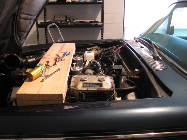 Geoff | ||
John Beech Prolific User Username: jbeech Post Number: 122 Registered: 10-2016 |
Geoff, nothing funny at all about your wood bench across the strut towers solution. I will fabricate something similar soonest because I suffer back problems and am in fact, laid up right now as a result of bending over the fenders whilst looking for the sender. Christian, I thought I had looked thoroughly on the back side of the cylinder heads but will look again. I have access to a remote inspection camera but it has proven difficult to use because holding the handle/viewfinder 'and' maneuvering the camera head - both at the same time - has proven awkward. Not worthless by any stretch but definitely less than ideal.  Robert Noel, as it happens, yes the fuel gauge is inoperative as well. Related development? Tell me more, please. Regarding coolant; my plan is to replenish with new by mixing up 5 gallons at 50/50, then draining the radiator, both heads, and the block. This, because I have no proof regarding when it was last done. Of course, disposing of old antifreeze-mix can be tricky because animals are attracted to drink it (thus becoming poisoned). This includes pets, (both our own plus neighbor's that wander), plus wild creatures like raccoons, turkeys, possum, bears, squirrels, deer, rats, mice, etc. because of the secluded nature of where we live. Thus, I will carefully collect it and subsequently take it to a disposal agent. Regarding the antifreeze-mix, I have not checked it for effectiveness because I'd rather renew it now and know for certain. Our climate isn't cold (Central Florida) but it certainly can be warm and thus, I prefer the mixture to be in optimal condition. Especially because like most preventive maintenance it's so inexpensive to do the job right. Regarding the radiator cap fitted to the coolant expansion tank, yes I have had it off. I also checked the rim is smooth and handled it carefully. This for the purpose of verifying visually the coolant level is proper because the amber light on the instrument panel does not illuminate when tested. I'm near certain this is the light connected to the sensor in the coolant overflow tank. Anyway, when I shorted these two leads manually (the two at the over flow tank), I expected the light to illuminate and since it didn't, I suspect the bulb. Anyway, as a further clue about the gauges, when pressing the test button, the fuel gauge DOES go hard over but the temperature gauge DOES NOT, and as I mentioned earlier, the amber light does not illuminate either. Anyway, with regard to the latter, I have secured replacement screw in bulbs (LED-type) and intend to replace this first before proceeding further. However, I would very much like your thoughts regarding the fuel gauge and the water temp gauge being inoperative. Meanwhile, I will go seek the sender location - once again - while awaiting your response. Many thanks. | ||
John Beech Prolific User Username: jbeech Post Number: 123 Registered: 10-2016 |
In conversation with Brian Vogel, he mentioned in passing the temperature gauge was deleted from the instrument panel at some point in Silver Shadow production. As of 1969, the gauge is present both in Tootsie's instrument panel and in her owner's manual - though the manual drawing does not mention the gauge there is a direct mention in the text of SRX68616's manual. 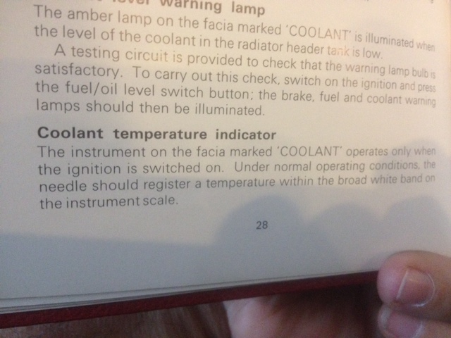 -Gauge, Coolant, per owner's manual 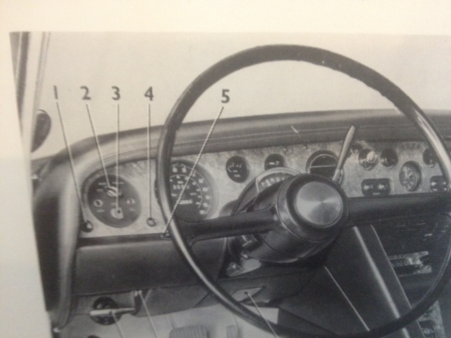 - Instrument panel, SRX6816, per the owner's manual 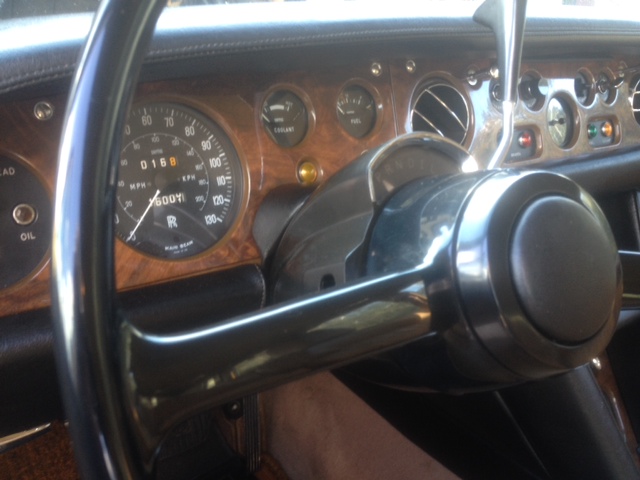 - Instrument panel, SRX6816, per the fact 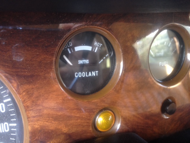 - Gauge, Coolant, SRX6816 | ||
Brian Vogel Grand Master Username: guyslp Post Number: 2162 Registered: 6-2009 |
Bob_UK wrote: "The fuel gauge on Lucas systems shares a voltage stabilizer ( standard Lucas bit not expensive ) if the fuel gauge reads correctly then the stab. is ok. " The following are clarifications requested for my curiosity, and for no other reason: 1. Define "Lucas systems" 2. Where is that voltage stabilizer located? 3. Is there a way to check whether the fuel level sender is sending something that gets "cut off" by a bad voltage stabilizer so that you might narrow what might be wrong on a car with no coolant temperature reading and a bad fuel gauge? Brian | ||
Jeff McCarthy Grand Master Username: jefmac2003 Post Number: 475 Registered: 5-2007 |
It is my understanding that there was no voltage stabiliser (of the sort Lucas used for Gauges) in the circuit. These gauges were apparently meant to run at 10V. Jaguar certainly fitted the little things on their gauges - Crewe simply deleted the Coolant gauge and bent the fuel level sensor a bit - I have tried several of these to get my coolant gauge to behave. I recently upgraded them for a more modern one which is voltage adjustable by a little screw. The idea is to get the engine running at a good temperature and then adjust it so the needle is pointing straight up. The modern reproduction Gauges have the voltage stabiliser built inside and are set at 10 volts. The only difference in appearance is that the word "Smiths" is slightly bolder and slightly more visible above the line of the bottom interior plate under the glass of the gauge. If I get time later I'll post a picture of both stabiliser types and of the repro gauges. | ||
John Beech Prolific User Username: jbeech Post Number: 124 Registered: 10-2016 |
Folks, believe it or not, I have yet to discover the location of the water temperature sensor! However, my point in writing is to ask Robert to elaborate further on the fuel gauge not working because, as it happens, it is not reading properly. Further to this, when I switch the car on, the fuel gauge needle rises to the empty mark, but no higher. Ditto the water temp gauge also doesn't rise beyond the lowest part of the white arc. However, if I press the test button, while the fuel gauge swings full scale, the water temperature gauge does not. Finally, please know before asking your advice, I have delved deeply into the workshop manuals as well as the exploded view diagrams, which form the parts manuals. In the drawings, I specifically looked at the head and the intake manifold for my serial number, which is SRX6816. Frankly, for the life of me, while I can find the water temperature gauge on the drawings and in my car, I cannot find the sensor itself on either drawings or car . . . and believe me when I say I have looked with both keen interest and great diligence. And finally, please don't merely laugh at me because a mechanic-friend with tremendous RR experience (retired from RR, owns 3 Shadows, 3 Clouds, and 3 Bentley to include an open wheel type) has looked as well and he couldn't find the sensor either! Seems improbable, I know, but there you have it. John who is perplexed, frustrated, and more than a little embarrassed. | ||
Geoff Wootton Grand Master Username: dounraey Post Number: 1517 Registered: 5-2012 |
Hi John My car is later so I do not know where this sender is located on the earlier cars. However, I have a suggestion which may solve a mystery. There is a small triangular plate on the side of the crankcase which apparently has no purpose. I'm wondering if it was used to mount the sender unit on the earlier cars. I used it as a location when fitting my temp gauge sender plug. Could you check this location, if only to rule it out. In the photo of my engine the U shaped air intake duct has been removed and the plate is arrowed. You may be able to see it with the duct in place (to save removing it) or with your remote camera. If you check this, could you report back. I am curious why the plate is there. 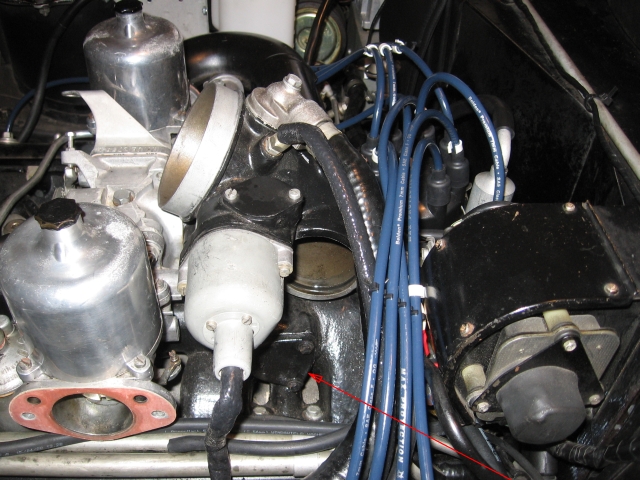 BTW I believe the button you press that sends the fuel gauge full travel is the oil level button, not a test button. This is the case on my car anyway. Geoff | ||
Robert Noel Reddington Grand Master Username: bob_uk Post Number: 1228 Registered: 5-2015 |
This sounds like a voltage stabilizer problem. Under the boot carpet is the fuel sender. 3 wires black is earth earth out the other 2 wires one should put on low fuel light and the other the fuel gauge should go to full if not the stab is most likely faulty. The stab is about an inch long by 1/2 by 1/2 inch has 2 terminals on the back and a resin sealed adjuster, the stab silver in colour. Shorting out the water level sensor should put the light out and open circuit should put the light on. | ||
Patrick Ryan Grand Master Username: patrick_r Post Number: 772 Registered: 4-2016 |
Gents, My car does not have the temp gauge, but what appears to be a non working ammeter instead. When the test button is pushed, all my 4 lights illuminate (2 brake, 1 coolant, 1 fuel. A loud buzzer also sounds, and the fuel gauge moves to full to show the oil level is ok. Gents, What are your experience with the ammeter? Should it move much, mine just sits dumbly one the middle regardless of what I do. | ||
Patrick Ryan Grand Master Username: patrick_r Post Number: 773 Registered: 4-2016 |
Geoff, I love your timber walkway over the engine. That's a fantastic tool and I need to make one immediately  | ||
Geoff Wootton Grand Master Username: dounraey Post Number: 1519 Registered: 5-2012 |
Hi Patrick Thanks. Re: the ammeter - With the ignition off the needle is vertical at 0. Normal running a slight deflection to the + side, maybe 1.5mm max at the top of the needle. On starting and for a few mins, maybe a 3mm deflection. The scale is very coarse on my ammeter -60 ~ 0 ~ +60 amps, so I would only ever expect very slight deflection of the needle. Geoff | ||
Carl Heydon Prolific User Username: car Post Number: 128 Registered: 2-2004 |
My 'walkway is much a lighter Hoop Pine plank, 290mm x 20mm. The screwed on pine strip feet sit in the gutter and so can be adjusted to move the plank anywhere over the engine. I used it yesterday to replace the ballast resister (again!). | ||
Patrick Ryan Grand Master Username: patrick_r Post Number: 778 Registered: 4-2016 |
Hi Geoff, No my ammeter just does nothing. Like me on a hot summer day (we had 41 degC 105degF last week here) is just refuses to budge. Geoff What about a cup/can holder in the timber walkway? Or an phone holder?  | ||
Robert Noel Reddington Grand Master Username: bob_uk Post Number: 1230 Registered: 5-2015 |
With engine running the ammeter should be around the zero mark thus indicating that the alternator has balanced the loads, which is correct. if the engine is off the heads lights on should show a discharge of 240 watts divided by 12v = 20 amps plus side lamps. built in radio and toilet seat! | ||
John Beech Prolific User Username: jbeech Post Number: 125 Registered: 10-2016 |
Geoff, I've seen the triangle-shape plate beneath the nearside carb of the intake manifold and there's nothing installed through mine (and yes, I've read a thread on this forum suggesting that plate as a location for installing a sender). Robert Noel, summarizing to ensure communication; 1. Of the three wires coming off the sender in the boot (pull back the carpet to expose the plate on which the sender is attached), the black wire is earth, and shorting one wire should illuminate the low fuel light, and shorting the other should send the gauge needle hard over. I will verify in the morning (it's nearly 2100 local and I'm watching an Australian production called Dr. Blake Mystery - lots of nice period cars - before heading to bed). Anyway, I'll check in the AM and report. Finally, regarding the voltage stabilizer, where is this located? Can it be serviced, or is it a throwaway and replace? And is it an easy to obtain item? Or . . . ? Last thing, what's the relationship between the voltage stabilizer for the fuel gauge and the water temp gauge; is it shared between them, thus performing a similar function? This would explain your earlier query regarding the fuel gauge within this thread. Many thanks for the guidance. | ||
Bob Reynolds Grand Master Username: bobreynolds Post Number: 439 Registered: 8-2012 |
If you look at this page: http://au.rrforums.net/forum/messages/17001/18164.html?1440447646 One of my posts shows an in-situ photograph of the temperature gauge sensor on the early Shadows. | ||
Robert Noel Reddington Grand Master Username: bob_uk Post Number: 1231 Registered: 5-2015 |
the stabilizer IF fitted works the fuel gauge and temperature gauge. The stab is because of voltage fluctuations which would affect the readings. Not serviceable. But twist screw anyway you maybe lucky When ignition turned on gauge moves slowly which is the stabilizer working except yours is giving low volts. Should be around 10volts The stabilizer is fitted to lots of brit iron but I dont know where it is. Standard Lucas part.0 Look near fuse board and guages. | ||
Mark Aldridge Grand Master Username: mark_aldridge Post Number: 376 Registered: 10-2008 |
Digital voltmeters that plug into the cigarette lighter socket are on Ebay for about �2. these are ideal for monitoring the charging circuit, which the ammeter struggles to do. | ||
Brian Vogel Grand Master Username: guyslp Post Number: 2163 Registered: 6-2009 |
Bob, This, I believe, is the photo to which you're referring:  and I've got to believe that the thing with the yellow wire in your photo is what is the coolant temperature sender. This is an image from the workshop manual for the two-series cars and their thermostat housing: 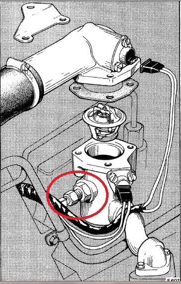 with the what I believe is the coolant temperature sender circled in red. If both your photo and what I circled are correct then there were early Shadows that had their coolant temperature senders in precisely the same spot as the two-series cars. I hasten to add that I am talking about the temperature sender for the temperature gauge, not the sender for the overheat warning buzzer. I hope that when the locations that have been discussed on the heads toward the firewall/bulkhead are alternate coolant temperature sender locations, not overheat sender locations. Brian | ||
John Beech Prolific User Username: jbeech Post Number: 126 Registered: 10-2016 |
Bob, I recall the thread as one I reviewed before ever asking about this (I really do try to search before bothering anyone). Anyway, I presume this is the photo you are referring to, and I see the yellow wire going to the water temperature sender and an unused Otter switch (like for controlling an electric fan). 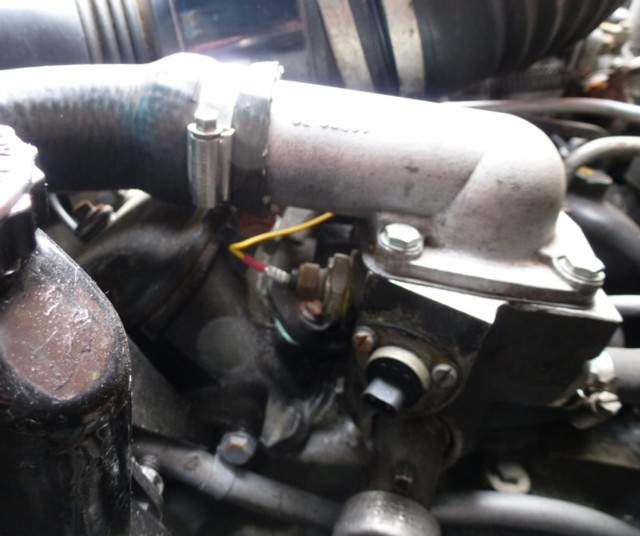 - Thermostat housing, Reynolds However, while Tootsie's thermostatic housing has a rigid line (very much like a brake line) coming out from the bottom and heading south, otherwise, it's smooth as a baby's butt, e.g. there is no sensor . . . and critically, no wire going to a sensor. This is a photo from above. 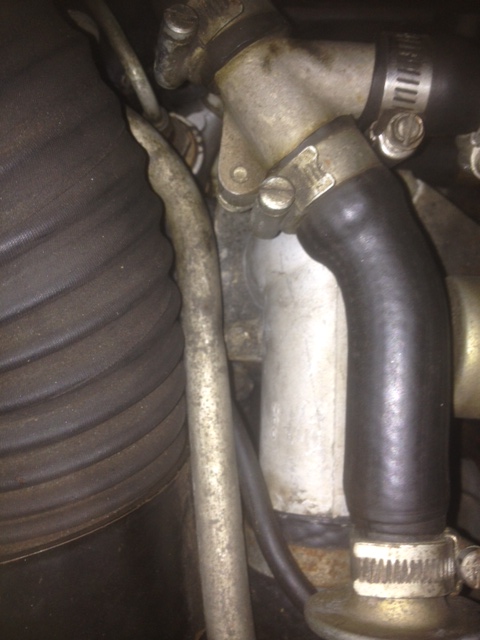 - Thermostat housing viewed from above When viewed from below (and from in front), you can see the boss for the rigid line/fitting coming off the bottom of the neck (where the radiator hose attaches). I have no clue why a rigid line goes from the neck where the upper radiator hose attaches but there you have it. 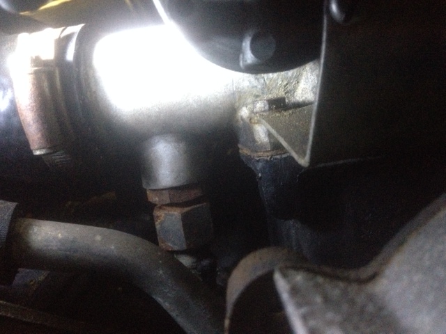 - Thermostat housing, viewed from below This is a transverse view (from just below the upper radiator hose) and looking back at where the neck for the hose departs the housings. This gives another view of the rigid line, and shows the lack of temperature sensor or Otter switch. 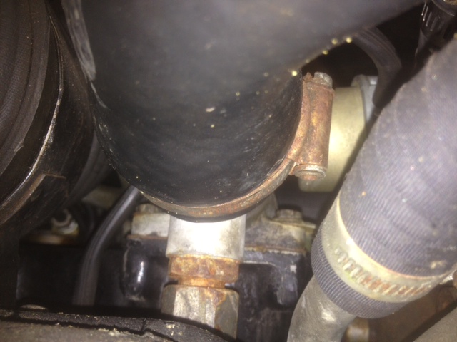 - Thermostat housing, transverse view from below Anyway, my frustration continues - no thermostat sensor in view (nor the wire leading to same) and certainly no Otter switch (which wouldn't remain long unused). In fact, I may seek out one of these style thermostat housings just for the ease of fitting an electric fan control switch! | ||
Jeff Young Prolific User Username: jeyjey Post Number: 296 Registered: 10-2010 |
Any chance the hard line is for a capillary temperature gauge (as opposed to electric)? Cheers, Jeff. | ||
Christian S. Hansen Grand Master Username: enquiring_mind Post Number: 462 Registered: 4-2015 |
John... While I may be accused of, and actually do at times, give crackpot comments, this time I believe that I am correct. There is a difference between Series I Shadows and VERY early Shadows, which I believe to be pre-10,000 range if not earlier, of which yours appears to be included based on your thermostat housing and output elbow photos which resemble mine which is definately of the VERY early ilk. The photos posted of the housing with the in-situ temp gause and unused otter switch is NOT for the VERY early Shadows. Except that my MPW (CRX2541) is in storage and not readily accessible, I would double check, but my recollection is that with a suitable light you can just see the end of the sending unit and wire by carefully looking down from above in the 1"-2" wide gap between the rear of the driver side head and the bulkhead. Do try again to find it there and keep in mind that the VERY early Shadows have notablae differences from the rest of the series and when looking at any manual illustrations and parts diagrams be sure that the chassis numbers covered are pre-10,000. P.S. That hard line from the bottom of the thermostat output elbow is also similar to mine and it goes down, disappears, and I have never traced to see where it goes or its function, and thus do not know. I can say however that the line must be disconnected if you desire to remove the thermostat, and in the porcess, DO NOT let the locking nut slip down the line as it becomes a hassle to retrieve it unless you have a helper. . | ||
Carl Heydon Prolific User Username: car Post Number: 130 Registered: 2-2004 |
This is the rear of the left hand head of SBH4346. I believe this is the spot.  |