| Author | Message | ||
Darryl Watson Experienced User Username: inox Post Number: 110 Registered: 04-2015 |
Hi, 1990 Mulsanne S. K-Motoronic PCME. I have replaced the air flow potentiometer but cannot find anything in the service manual regarding voltage adjustment. The voltage between pins 1 & 2 is .8v. I have Udo's post from 2010 but that's about a Jetronic. Can anyone supply me with the information please (I have scoured the internet to no avail). Many thanks, Darryl | ||
michael vass Frequent User Username: mikebentleyturbo2 Post Number: 617 Registered: 07-2015 |
Show me a pic Darryl I don't know what you mean. | ||
Darryl Watson Experienced User Username: inox Post Number: 111 Registered: 04-2015 |
Hi Michael, Please two photos. I marked the metalwork before removing the old faulty potentiometer so that the replacement was in the same place as near as possible. The pot-r has slots and a screw to adjust the voltage across (I believe) to top; and middle plug connections. Best regards, Darryl 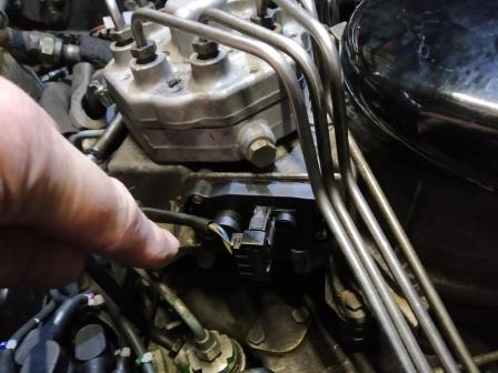 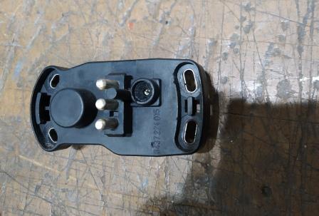 . | ||
Udo Hoffmüller Experienced User Username: udo Post Number: 101 Registered: 02-2008 |
True, there is nothing in our workshop manual about adjusting the airflow potentiometer. It only says that the whole unit should be replaced. The setting is a bit fiddly and must be done very precisely. The four screws holding the potentiometer are loosened a little so that the position of the potentiometer can be changed slightly upwards or downwards by tapping a screwdriver gently. A wire is attached to pins 1 and 2 of the potentiometer plug so that the voltage can be measured with the multimeter. Now let the engine warm up. The motor will probably not run perfectly because the potentiometer has not yet been set correctly. The current voltage can be read on the multimeter. When the engine has warmed up, you can read the voltage. The value should be as close as possible to 0.75 V, but not above 1 V. By tapping the potentiometer lightly with a screwdriver, you can adjust its position (downwards: less voltage, upwards: more voltage), and at the same time it changes voltage. Very small movements cause a significant change in voltage. You have to find a position of the potentiometer in which the voltage is between 0.75 V and 1 V (for my TurboR the value is just under 1 V). Please do not turn the small screw located in the potentiometer housing. Otherwise you will destroy the basic setting found by the manufacturer. If you adjust the screw, you will never have a satisfactorily working potentiometer. When the engine has warmed up and the correct voltage has been set on the potentiometer, the engine should run properly at around 580 rpm. Now the four screws of the potentiometer can be tightened carefully, the potentiometer must not slip, otherwise everything was for nothing, and you can start again. It is important that the idle was already set correctly before changing the potentiometer. The potentiometer cannot be adjusted properly without the idle set correctly. To help you determine the correct voltage on the potentiometer, look at the diagram: 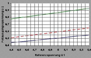 The EngineECU produces a reference voltage that is around 5 V. A difference of 0.05 V is already significant. The relation between the reference voltage of the EngineECU and the signal voltage of the potentiometer is shown in the diagram. The diagram applies to exactly our potentiometer. In our workshop manual there is information that the signal voltage of the potentiometer should not be more than 1 V. So I'm not sure if this chart really applies to Rolls-Royce/Bentley. According to the diagram, a signal voltage of 0.9 V is already outside the permissible range, which is limited by the red lines. With our TurboR, I am above the red line in the diagram. The O-ring on the potentiometer measures 2 mm x 60 mm. It should perhaps be replaced so that really no moisture gets inside the potentiometer. Why did you change the potentiometer? Can you show us a picture of the conductor line of the potentiometer? There you can usually see heavy wear on the contact surface where the engine is idling. I hope I could help. Regards - Udo | ||
michael vass Frequent User Username: mikebentleyturbo2 Post Number: 618 Registered: 07-2015 |
Thanks Darryl and Udo , I've learned a bit more about my car! Cheers Mike | ||
Darryl Watson Experienced User Username: inox Post Number: 112 Registered: 04-2015 |
Udo, Thanks for the comprehensive reply . I appreciate your time and effort. Best regards, Darryl | ||
Darryl Watson Experienced User Username: inox Post Number: 113 Registered: 04-2015 |
I forgot to mention that the track was worn on the old unit and when the flow plate was moved the needle on my trusty Avo 8 test meter jumped about. Regards, Darryl | ||
Darryl Watson Experienced User Username: inox Post Number: 114 Registered: 04-2015 |
Hi, Fitted the pot and the reading is 9.3v varying slightly because the engine is running a little unevenly. (See my post on timing). If I adjust the pot�s body to read .75 volts the engine idle at approx. 800 rpm. With 9.3v it idles at about 615 rpm which has been the idle speed since we purchased the car nearly 26,000 miles ago. Regards Darryl | ||
Udo Hoffmüller Experienced User Username: udo Post Number: 104 Registered: 02-2008 |
I have the same problem with our TurboR. After replacing the potentiometer, the voltage was similar to yours. I think that's not wrong. First of all, our workshop manual says that the voltage should not exceed 1V - you are below, as is me. Secondly, you have to measure the signal voltage of the electronics. For example, at 5.3V or 5.25V signal voltage and then with 0.93V you are still within the specified limits. In addition, a voltage difference of 0.05 V is only 1%, since the measuring accuracy of our amateur measuring devices is greater. Therefore, it may well be that you with 0.93V do stay within the specified range, taking also into account errors in measurement accuracy. The engine of our TurboR does not run completely smoothly at around 0.93V. But the engine ran more than 300,000 km. Many parts have wear that the EHA and the lambda sensor together cannot completely correct. You should measure the current at the EHA when the engine is warm. If the value fluctuates at 0 mA +/- 3 mA, you already have the explanation for the somewhat unsmooth running of the engine. The warm engine does not actually need the EHA when idling and in normal operation. Disconnect the plug from the EHA while the engine is idling - the engine must continue to run unchanged. Regards - Udo |