| Author | Message | ||
Mark Peacock Prolific User Username: takemehomejames Post Number: 50 Registered: 4-2004 |
I have a 85 spirit with an inoperative speedo. And as its electric driven (sender), is there any common faults with it ?? And the best way to check the signal ?? | ||
Richard Treacy Grand Master Username: richard_treacy Post Number: 579 Registered: 4-2003 |
Mark, Have a look at this: http://au.rrforums.net/forum/messages/17/1156.html#POST3117 | ||
Mark Peacock Prolific User Username: takemehomejames Post Number: 50 Registered: 4-2004 |
Richard..will have a look.. thanks.... | ||
Richard Treacy Grand Master Username: richard_treacy Post Number: 544 Registered: 4-2003 |
By the way, Mark, if the cruise control works properly, you could safely assume that the speed pulse sender is OK. RT. | ||
Mark Peacock Prolific User Username: takemehomejames Post Number: 51 Registered: 4-2004 |
Richard , the car has sat for about 3 years with no use, and only has 30,000 kms on the clock. The previous owner has just passed away, with his brother now in possesion ,he just brought it round for an oil change and a once over for rego.. and the speedo did not work. Ive been away from the car for the last 7days as ive just welcomed my First Daughter into the world (lauren)!! (there goes my sleep )! and i'll be back into the workshop on monday and have a look. The 'Brother',apparently removed the unit from the box and mentioned that i came apart in a few pieces.?? With the cost of a replacement, im hoping he hasn't damaged the sender. But what seems strange to me is It was working before the car was stored , then after sitting it did not work.... If i put a multimeter on the output terminals on the sender unit, what sort of reading should i get.. ?? Thanks. Mark P | ||
Richard Treacy Grand Master Username: richard_treacy Post Number: 553 Registered: 4-2003 |
Attached is a circuit diagram of the sender. You will see that it is a very simple and mostly repairable device, although a failed coil is very difficult to repair unless it is just a broken end lead. To diagnose, measure between the lead and the case: If the sender behaves as a pure silicon diode (select ohms, or diode test if you have a digital meter), it is probably OK. However, if it does not check out when turning the spindle (see below) check that the diode has not short circuited (you need to unsolder one lead to do this). If it behaves like a diode with leakage, expect to find some corrosion on the PCB to clean off. Otherwise the transistor may be on its way out. If it is a short circuit the transistor has failed. Any low-power NPN transistor will replace it, but take care with the pinout. If it is an open circuit, suspect the coil or a bad connection. When you turn the spindle, you should be able to see an AC voltage on the meter. If you have a non-digital meter, connect it to the most sensitive DC current range, and the needle should flick backwards and forwards when you turn the spindle gently. 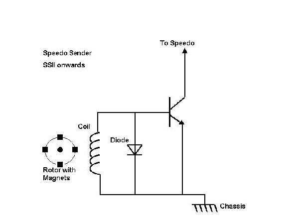 | ||
Richard Treacy Grand Master Username: richard_treacy Post Number: 554 Registered: 4-2003 |
Mark, If you do test the sender with a conventional meter, could you let me know how many pulses there are per revolution. That way I can buy and test an aftermarket one from Magnetic Sensor Corporation. | ||
Richard Treacy Grand Master Username: richard_treacy Post Number: 556 Registered: 4-2003 |
Sorry, Of couse I showed the diode back-to-front. This diagram is correct.  | ||
Mark Peacock Prolific User Username: takemehomejames Post Number: 52 Registered: 4-2004 |
RT, Firstly i took the sprirt for a leasurely drive to test the cruise control, but to no success. It did not engage , nor did the speedo needle flicker at all. So next to the hoist to test the SPS (speed pulse sensor.. I removed the speed pulse sensor (SPS) from the auto and tested on the bench. Using a digital multi-meter i found some advancement in the voltage, using my hand to crank the drive gear. So, then i re-installed the "SPS" back in the auto and hand turned wheels/tailshaft to simulate road speed , and yet again using the meter , i found a signal. So, by now i assume that the "SPS" is ok?? So, my next Q is, ive looked thru the w/shop wiring diagram, but find no reference to testing pulse at the speedo end (in the wires) in the dash.. I know now how to check the pulse via A/C volts , but, is that the same way , and what terminals do i check ??. It would be nice if the factory manual/ diagrams would show what terminals are from the "SPS". Also , is there any way the signal is fused by any means ... the reason i ask is, because its strange that the car lost the speedo signal because it sat idle for 3 years with no use !! By the way .../ thanks for the help... Electrics are my down fall !!! | ||
Richard Treacy Grand Master Username: richard_treacy Post Number: 556 Registered: 4-2003 |
Mark, Here is the wiring diagram. The wire to the cruise control was changed in production from blue with a yellow stripe (UY) to red with a green stripe (RG) in May 1985. Next steps: Disconnect the leads at the sender (one black, and the other green connecting to a red one with a green stripe on the car side). On the car side of the connections, the black lead should show good continuity to the chassis. With the ignition turned on, the RG should show around 10VDC on a digital multimeter. If not, disconnect the cruise control ECU and try again. If there is still no voltage, then suspect the fuse or the wiring. The next step in that case it to check for 12VDC at the speedo head, and work your way backwards or forwards as suitable. If that all checks out, reconnect it and turn the wheels with the ignition turned on. You should read around 5VAC RMS across the sender leads or between the RG or green lead to the chassis using an AC multimeter. If not, I still bet that the PCB inside the sender has simply corroded during storage. They do that during storage or after a steam clean underneath, and I have explained how to cure it already. With corrosion, the signal may still be there, but too weak to power the speedo. Note that, when rotating the sender with the ignition turned off, the signal at the sender will be only 0.3 VAC RMS or so due to the diode effects. With the ignition turned on it should be around 5VAC RMS on a multimeter using an AC range (the transistor is then switching from OVDC to 10VDC). On a DC range, it should read 10V stationary, and then quickly drop to 5VDC with the wheels/sender turning. | ||
Richard Treacy Grand Master Username: richard_treacy Post Number: 557 Registered: 4-2003 |
Something strange happened to my earlier post of February 19: the graphic change when I loaded the last one. Hmmn. Here is the correct sender schematic with the diode in the correct direction in any case. 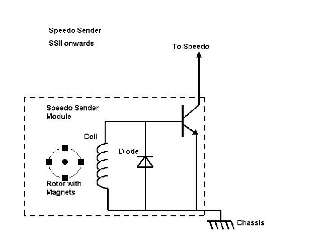 | ||
Mark Peacock Prolific User Username: takemehomejames Post Number: 53 Registered: 4-2004 |
Thanks again richard..Your information is very much appreciated. I'll be back on the job on friday to test some more.... Another Q is .. You mentioned that there is a fuse ?? I looked under the dash in the fuse box, but no individual fuses for the guages ?? Also, When i used the multimeter to test the output of the SPS i only got a reading of .03 VAC. So it may be corrode. I did't pull it apart to see. I will tomorrow. | ||
Richard Treacy Grand Master Username: richard_treacy Post Number: 558 Registered: 4-2003 |
Mark, The same fuse feeds the instrument panel and the warning lamps. There is no additional fuse for the speedometer, so if the lamps function the fuse is not the problem itself. RT. | ||
Gordon Norris New User Username: crewes_missile Post Number: 3 Registered: 2-2005 |
Just wanted to point out a possible correction on this and related threads about the speedo. I've seen it referred to that this problem applies to ALL cars from SS11 onwards. However, for 1990 cars onwards the speedo signal actually comes from the ABS ECU in the boot (if memory serves me correctly the speedo signal wire is pin 17 on the ECU...had to tap into it to install satnav) So speedo problems on post-1990 cars are usually in the speedo itself. However, for some reason the cruise control still gets its signal from the same naff sender on the gearbox referred to above, so if your cruise plays up, check it as per the procedure so thoroughly outlined by Richard. Hope this is helpful.  | ||
Richard Treacy Grand Master Username: richard_treacy Post Number: 575 Registered: 4-2003 |
Gordon, That's probably correct. The signal is certainly present on the ABS ECU, pin 17 on cars from Chassis 30,000. The transducer on the transmission is the same type on all SSII and SZ cars with slight but insignificant physical variations along the way. On cars from chassis 20,000 the speedo signal still comes from the transducer on the transmission, and these cars have ABS. Maybe on later cars the transducer is only for the cruise control as the sensor is still there ??? I note that cars from Chassis 30,000 apparently have a different ABS ECU which may explain this. RT. | ||
Richard Treacy Grand Master Username: richard_treacy Post Number: 576 Registered: 4-2003 |
I just looked this up, and Gordon must be correct. From Chassis 30,000 there seems to be no connection between the speedo and the transmission mounted sensor. It connects to the ECU pin 17 as stated. I always assumed that the transducer fed the speedometer and the ECU as a reference signal. Oh well. The transmission speed sensor is still there as pointed out, but apparently only for the cruise control. What a waste. Again we ask... why ? RT. | ||
Gordon Norris New User Username: crewes_missile Post Number: 4 Registered: 2-2005 |
Richard, Why make things simple when you can make it complex? OR, for the conspiracy theorists: why get rid of a part that generates mucho servicing and parts income!  GN. | ||
Gordon Norris New User Username: crewes_missile Post Number: 5 Registered: 2-2005 |
Actually, I'm glad my memory was right re pin 17...amazing what flotsam and jetsam we retain... One day, when my cruise cuts out probably, I'll compare the frequency and current of the outputs from the ABS signal and the gearbox sender. If they are close then a permanent fix would be to link the ABS/speedo signal to the cruise, and do away with the gearbox unit. Unfortunately, I suspect they are vastly different/incompatible, and that is probably why they retained the troublesome gearbox sender for the cruise control. It does raise some possibilities though... GN. | ||
Richard Treacy Grand Master Username: richard_treacy Post Number: 579 Registered: 4-2003 |
I bet you a Chicco Roll and an FJ Holden that the Cruise Control will work perfectly from the ABS ECU as long as the ECU can serve the load. On my R-Type, I run the cruise control from the engine speed (connection to the points) and it works perfectly. On my BMW, the CC used to start at 30 km/h but topped out at 170km/h, so I built a frequency divider to double the limit, using a CMOS IC and a few diodes, as I drive often in Germany. It is OK at any speed from 60 km/h upwards now. The CC is not critical to pulse rate, whereas the speedo must be +/- 1%. By the way, a VN Commodore uses the same Cruise Control ECU as does your post 20,000-series Bentley. | ||
Gordon Norris New User Username: crewes_missile Post Number: 6 Registered: 2-2005 |
Richard, You're probably right...Chiko roll and FJ being readied for despatch when my cruise cuts out... Thanks about the ECU info, but I'd already noted the VDO serial numbers on the unit some time ago when I was exploring under the driver's dash area, and (pleasingly) discovered the VN uses the same. Haven't had to price one yet, but I'll bet you 2 chiko's and a Sandman Panel Van the Holden one is cheaper. GN. | ||
Gordon Norris New User Username: crewes_missile Post Number: 7 Registered: 2-2005 |
Richard, Of course, if you are correct it brings us full circle again as to WHY they retained the @#*&% gearbox sender for the cruise....My conspiracy theory is looking stronger!! GN. | ||
Mark Peacock Prolific User Username: takemehomejames Post Number: 54 Registered: 4-2004 |
RT, Sorry for the late reply, ive been knee deep in nappy's and all things 'baby' for the last few weeks, since the new arrival of Little Lauren !!. I finally got to the bottom of the "inoperative speedo". Firstly, I removed the SPS (speed pulse sensor) from my shadow 2 (SRH31689), and installed to the spirit and then ran it up to speed on the hoist,only to find that i still did not have a reading. So, i sent the speedo to General Instruments, to find that a diode had gone.. So, then i re-installed the speedo to the car and re-tested again , only to be disappointed again. So, then i removed the SPS again, only to find some corrosion. So , i cleaned the unit as mentioned in your earlier post, and hey presto !! it worked. I then tought about inspecting the original SPS and whilst removing the internals out of its casing i found that a wire had broken off , just short of the circuit board. So , i soldered the wire back together, cleaned all the oil adn grime away, reinstalled it back into the car .. hey presto!! it worked too. So all in all, it ended up a bad diode in the speedo and a broken wire in the SPS.. Thanks for the help !! Mark. |