| Author | Message | ||
Jean-Pierre 'JP' Hilbert Prolific User Username: jphilbert Post Number: 102 Registered: 9-2013 |
Update: as I'm overhauling my gearbox, I now have unobstructed access to the electric gearbox actuator. So out it comes, and as soon as the elastic gasket stopped fighting me and I was able to remove the top, I spotted one of the microswitch rollers stuck on the side. This roller belongs to the microswitch where the brown-white cable leaves towards the reverse lights. Bingo! Pictures say it all. Now where do I get such a new microswitch? It's a Burgess VCF/1591. AN internet search lead me to a variety of switches, but which one is the right one? Anyone with experience in that department? 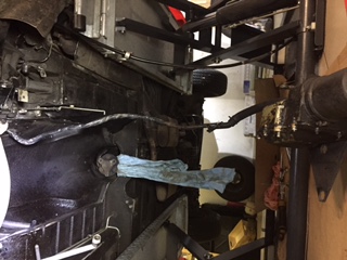 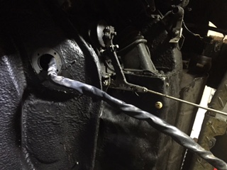 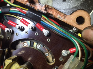  | ||
Brian Vogel Grand Master Username: guyslp Post Number: 1618 Registered: 6-2009 |
JP, I've seen your post here and elsewhere regarding this question and I'll offer what I can, though I've not dealt with this particular microswitch. Virtually all of the microswitches that look as though they have the correct "switch directly beneath roller arm" layout I've found after doing eBay and web searches are all rated for far higher AC loads than they'll ever see in a DC automotive application. Here's one example at newark.com. The technical data sheet that you can get via that page lays out the entire line of switches and their physical configurations, so you should be able to derive the correct part number by matching up the one you have to the correct tech specs with regard to size and roller-arm layout. Here's an example on Amazon that won't fit your specific application, but it was a rare one that included a DC rating alongside its AC rating and it gives you a clear idea that something rated for 250V DC (which seems to be very common) can certainly handle 12V DC. Since what used to be AmazonSupply has migrated a lot of their stuff under "Industrial & Scientific" category on Amazon proper you'll find a lot of other options there, too. I'd also be shocked if some of the suppliers I've posted about in the past for relays don't also carry micro switches that would work in this application. Since I can't see the end of your switch opposite the roller arm end I don't know whether it's an SPST (single pole single throw) or SPDT (single pole double throw) switch. Based on what I can see in one of the photos I suspect SPDT. Even if it's SPST (single input, single output, normally open) you can use an SPDT in its place (single input, two outputs - one normally closed and one normally open) if it fits without the NC terminal interfering with anything else simply by connecting only to the NO terminal. You can put liquid tape or the like over the NC terminal if you feel that's necessary. My guess is that virtually anything that actually fits correctly will work just fine for this application, but just check the tech specs first. Brian, who went through a microswitch search related to the interior lights a while back | ||
Jean-Pierre 'JP' Hilbert Prolific User Username: jphilbert Post Number: 104 Registered: 9-2013 |
Brian, many thanks! This microswitch put the reverse light ON when energised (squashed), right? So it should be of the SPST-NO type? The micoswitch has 3 connectors, what do they do? The middle one is the brown-white wire going to the reverse lights. Also, the fuse protecting the reverse lights is 20A. If I chose anything less than 20A, then the microswitch will grill before the fuse, right? Attached a better pic also showing the missing roller. JP, who is seriously dyslexic with anything electric.  | ||
Brian Vogel Grand Master Username: guyslp Post Number: 1619 Registered: 6-2009 |
JP, I'm not much better as far as electrical dyslexia, but switches I can handle. You've clearly got a good, old fashioned single pole double throw (SPDT) roller arm microswitch there. The wire going into the bottom of the switch is the 12V power source. On virtually every diagram of this type of switch I've ever seen the upper of the two terminals on the switch has continuity when the switch is not depressed (it's the Normally Closed [NC] terminal) and the lower of the two obtains continuity (and the upper loses it) when the switch is depressed (it's the Normally Open [NO] terminal). It's a simple test to determine whether this is the case with a multimeter that has a continuity setting. I would presume that you are correct that the current gets sent to the reversing lights only when the switch is thrown to the "on" position and the NO terminal is supplied with juice. I have no idea (without looking at a wiring diagram) where that juice goes to when the switch is off and the NC terminal is the circuit that's completing. I am not the best with electrical math, particularly when it comes what an AC rated switch can do in a DC application, but, I can draw a reasonable inference based upon a chart regarding same. This image comes from the second page of the technical specification sheet at farnell.com that I alluded to in my prior post: 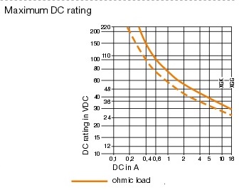 They don't even draw the lines down to 12V DC, but extrapolating based on the trend shown it's pretty darned likely that these switches will deal with well above 20A DC in a 12VDC application. I have a question out to someone who can confirm or refute whether my extrapolation is valid, and I will definitely post if I'm informed it's not valid. Until then I'd operate under the assumption that you're in virtually no danger of frying your micro switch before your fuse would blow in a 12VDC situation. Brian | ||
Brian Vogel Grand Master Username: guyslp Post Number: 1620 Registered: 6-2009 |
JP, Also see the tech spec sheet for this Omron micro switch which is listed as an alternative for the SAIA-Burgess I posted before (though the pin layout is not what you'd want). What different manufacturers include in their spec sheets is interesting. Pay close attention to note 4 under the General Ratings table shown on PDF page 2. Brian | ||
michael vass New User Username: mikebentleyturbo2 Post Number: 10 Registered: 7-2015 |
Hi All In my experience it's the type of load as well as the current that will kill a switch , inductive loads need to bee a lot less than the current rating, obviously reversing lamps are not so your 20A switch should last years. 21w x2 = 42w 42/12=3.5A Hope that helps Mike | ||
Jean-Pierre 'JP' Hilbert Prolific User Username: jphilbert Post Number: 105 Registered: 9-2013 |
Brian, Now that's a qualified answer, but that's what you are known for, aren't ya! Now, IF it is SPDT and IF I can install something lower than 20A, then this opens a new window to the universe of microswitches! I did spend more than one hour over the Omron spec sheet this morning, your info provides clarification, rectification and ...complication, because it puts me back to square one, as the education you provided leads me to further questions, which hopefully you or any bystander have an answer for (and by that I mean, an answer which even myself can understand))). But let em get my thoughts together before I post anything more. Meanwhile, attached a pic of the switch as found in my car. Can you see if this is the SPDT? 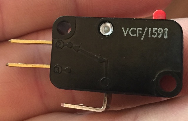 | ||
Jean-Pierre 'JP' Hilbert Prolific User Username: jphilbert Post Number: 106 Registered: 9-2013 |
Mike, Your message crossed mine, may I ask you to explain to an electrical neophyte what you tried to say with your calculation. Many thanks indeed! JP | ||
michael vass Experienced User Username: mikebentleyturbo2 Post Number: 11 Registered: 7-2015 |
Hi Jp No problem ,each bulb is 21 watts 2 of them = 42w ok Car voltage is about 12volts ok , watts divided by volts gives amps ok so 3.5 amps on the switch ok Hope that helped Mike ps thanks for the useful pictures | ||
michael vass Experienced User Username: mikebentleyturbo2 Post Number: 13 Registered: 7-2015 |
Hi Again JP Just looking at your picture are you sure the switch is faulty or is it the actuator arm that is broken? I can't see the little white roller usualy found on the end? Cheers Mike 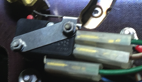 | ||
Jean-Pierre 'JP' Hilbert Prolific User Username: jphilbert Post Number: 107 Registered: 9-2013 |
Mike, You most likely missed that I mentioned in the very first sentence on this thread that the roller broke off the metal lever. The microswitch is absolutely serviceable, it is merely that metal lever which is broken. Below a pic of the broken-off (and missing) roll on the right, and it's equivalent, intact, counterpart on the left of the bronze rotary cam. The last picture of my initial thread shows the same view, with my oily thumb painting towards the missing roller.  | ||
Brian Vogel Grand Master Username: guyslp Post Number: 1621 Registered: 6-2009 |
JP, Look at the last picture you posted of the back side of your existing switch, showing the circuit diagram, and that shown in the tech sheet for the SAIA-Burgess SPDT switch: 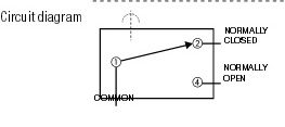 They are one and the same (the numbers or letters used for the terminal designations are arbitrary - and I think the use of 3 on your switch makes more sense than the use of 4 on the diagram above). I only wish I could find an ancient tech spec sheet from way back when for the Burgess VCF/1591. That could put virtually all questions about what currently available micro switches are crossover replacements for it to rest. Also, when thinking about switches or relays the terminology is the same as far as how many power sources come in and how many switching options come out. On a single pole that simply means that there is a single terminal on which the incoming current is supplied. The number of throws is how many outputs to which current can be passed. This entry entitled Switches in Electronic Circuits: Poles and Throws in the for Dummies series online does a very good job with this. A SPST switch is simply an on/off switch. It has a single hot input, and a single output that is either hot or not depending on whether the switch is thrown or not. If the switch is normally open (NO) that means that "off" is its resting state and "on" is its thrown state. Normally closed (NC) is vice versa. An SPDT switch (or relay) is sometimes referred to as a changeover switch because the current is always being passed through to at least one of its output terminals depending on how the switch is thrown. There is no "off" state, really, for an SPDT switch. It's a matter of which of the two terminals is "on" based on which direction the switch is thrown. Of course, if you omit a connection on one of the two output terminals of an SPDT switch you have a functional SPST switch. You just need to know whether you need to hook up your one output line to the NO or NC terminal based upon whether the original SPST switch was of a NO or NC configuration (or what you're doing with the circuit you're designing). I have also asked my "source" (who has yet to reply) if there's a simple [or even not so simple] method of determining DC specs on a switch that's only got AC specs on its spec sheet. Brian, who's done the best he can on this one (and is not sure whether "qualified answer" means "answer with qualifications" or "answer from someone qualified to give it" when you used it. In this case it's definitely the former with an outstanding query to someone who can make it a fully complete answer) | ||
Robert Noel Reddington Grand Master Username: bob_uk Post Number: 453 Registered: 5-2015 |
Volts x amp equal watts. The voltage rating is not the point. It's the amperage thats important. At 240v the amperage for N watts is a lot lower than 12v for the same N watts. 20 times lower by the maths. Example 30 amps at 12v is 360 watts. 1.5 amps at 240v is 360 watts. Electrical maths is always correct. The voltage rating is about insulation. The higher the voltage the better the insulation has to be. Example spark ignition. | ||
Brian Vogel Grand Master Username: guyslp Post Number: 1623 Registered: 6-2009 |
From everything I've found you can't apply straight electrical math when dealing with switch ratings. The best "rules of thumb" I've found so far from sources I trust are: 1. DC Rule of Thumb For those switches that list an AC voltage rating only, the "DC Rule of Thumb" can be applied for determining the switch's maximum DC current rating. This "rule" states the highest amperage on the switch should perform satisfactorily up to 30 volts DC. For example, a switch which is rated at 10A 250VAC; 15A 125VAC; 3/4HP 125-250VAC, will be likely to perform satisfactorily at 15 amps up to 30 volts DC (VDC). [See the webpage at Carling Technologies entitled, Amp Ratings, HP, Volts] 2. In a nutshell, 125 VAC ratings equate favorably and conservatively to 14 VDC ratings - as long as the switch has a healthy "snap" action . . . all toggle switches and most rocker switches do. Just because the numbers stamped onthe side of the switch don't mention a DC capability doesn't mean that the switch doesn't have one. Manufacturers are unable to put ALL of the information from the chart onto the side of every product, the lettering would be too small to read! [Note: For the full article from which this is taken, which is on the subject of switches in aeronautical applications, see Switch Ratings: What's it all Mean? which is 13 pages long.] 3. To err on the side of safety, read the specifications thus: Rated to allow up to 10A at up to 125VAC or up to 6A at up to 250VAC. Not actually rated for DC, so you're on your own. In other words, if at all there is a choice, opt for a DC-rated switch, so you know you are within rated parameters. If, however, that is not an option, read on... Some of the factors that affect a switch contact rating:
Thus, when used for DC, I prefer to assume 10% of the highest rated AC voltage, while keeping the current rating the same as the lowest rated current for the AC specifications. For this particular switch, 6 Amperes at 12.5 Volts DC would not trigger a paranoia attack. [See discussion thread on webpage: http://electronics.stackexchange.com/questions/53310/calculating-current-load-for-a-switch] ---------------------------------------------------- In the final analysis the the correct switch in the "family" of this SAIA-Burgess micro switch I posted a link to waaaay back up in the thread should be more than up to the job. At this point I bow out until/unless my earlier private query produces a response worth posting about. Brian | ||
Brian Vogel Grand Master Username: guyslp Post Number: 1627 Registered: 6-2009 |
I've now had two electrical engineers weigh in on the "Rules of Thumb" I posted before and the consensus is that numbers 1 and 2 are both entirely reasonable and number three, while perfectly safe, is way overly conservative in a 12V automotive application. Several things that have been shared with me that are worth listing here:
Brian | ||
Jean-Pierre 'JP' Hilbert Prolific User Username: jphilbert Post Number: 109 Registered: 9-2013 |
OMRON D3V-165-1C5 is what I now installed. It works, and I left the reverse lights running ON throughout lunch before I closed the actuator box for good. Interestingly, the 12V source to the reverse lights are coming from the green NC wire (upper terminal on the left microswitch), and not going through the white-brown NO wire, however, the brown-white wire is found back wired to the reverse lights and it does say so throughout the wiring diagram. I'm puzzled. Also, Is this current not controlling a relay first, and not directly the reverse lights? 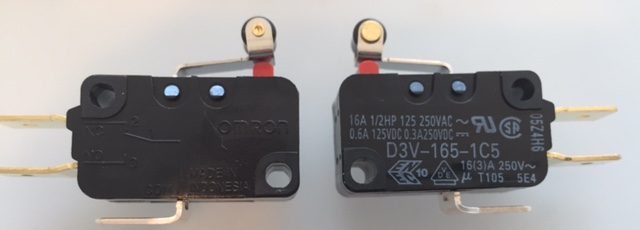 | ||
michael vass Experienced User Username: mikebentleyturbo2 Post Number: 15 Registered: 7-2015 |
Hi JD There is no relay but it does go through the RD1L microswitch too ,did you replace all the switches? best wishes Mike | ||
Jean-Pierre 'JP' Hilbert Prolific User Username: jphilbert Post Number: 110 Registered: 9-2013 |
Mike, I only replaced the faulty one. I'm afraid of disturbing the others, and that the replacement will cause more trouble than leaving the existing ones alone. Any thoughts? | ||
Brian Vogel Grand Master Username: guyslp Post Number: 1632 Registered: 6-2009 |
JP, My philosophy is never fix a functioning component except if said component is known to be failure prone and is difficult to access. I have seen more induced failure secondary to trying to fix was isn't broken than I care to recount. "If it ain't broke, don't fix it!," has always made infinite sense to me. Yours is the first instance of one of these micro switches I've seen fail and the failure appears to have been strictly the roller arm. Were you able to tell anything about how it failed? (There would likely be evidence of some bending if the roller got bound up then bent & snapped by the brass actuator versus a perfectly clean break with level arm otherwise). I would do exactly what you did with regard to the undamaged and functioning microswitches: nothing. Brian | ||
Bob Reynolds Grand Master Username: bobreynolds Post Number: 331 Registered: 8-2012 |
"Interestingly, the 12V source to the reverse lights are coming from the green NC wire (upper terminal on the left microswitch), and not going through the white-brown NO wire, however, the brown-white wire is found back wired to the reverse lights and it does say so throughout the wiring diagram. I'm puzzled. " I can't tell from the photos, but this is possibly because the microswitch is normally operated, and when reverse is selected the roller falls into a notch and the microswitch releases. Therefore, the NO and NC contacts are effectively reversed because of the way the microswitch is operated. |