| Author | Message | ||
Brian Vogel Grand Master Username: guyslp Post Number: 720 Registered: 6-2009 |
Hello All, First, what is the terminology that Crewe uses in documentation for this item? Second, where is it located on SZ series cars over the course of their run. I'm trying to help someone with a 1989 Spur, but it never hurts to know where this little box resides regardless of the model year. With any luck it's one of those things that didn't wander over the years. Photos would help. I did find the supplement to chapter 28 in TSD4701, but I'm not at all good with electronic diagrams. It would be very handy to see what these things actually look like when the case is removed and which bits should actually be replaced. Thanks in advance for any and all assistance. Brian | ||
Graham Burn Experienced User Username: graham Post Number: 47 Registered: 6-2013 |
Hi Brian, don't know if it's any help to you but on my '87 Turbo R RHD its behind the right hand end of the fuse box when you release the 4 screws which hold the fuse holders in place. I think it's described as a delay unit, I managed to get mine working again by opening it up and cleaning the relay contacts inside, if your friends unit is the same it's worth a try. Hope this helps Graham | ||
Brian Vogel Grand Master Username: guyslp Post Number: 721 Registered: 6-2009 |
Graham, Thanks for the input. This item seems to be one of those that routinely causes trouble for many once it gets to be "of a certain age." So far I've escaped that fate on my SYs, but I'll bet just by typing this I'll break that lucky streak!! Brian | ||
Mark David Smith New User Username: detroitbrit Post Number: 7 Registered: 7-2013 |
hope this diagram helps 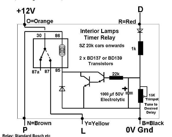 | ||
Graham Burn Experienced User Username: graham Post Number: 48 Registered: 6-2013 |
But note that the diagram is of a home made alternative to the original and not the original unit. Graham | ||
Brian Vogel Grand Master Username: guyslp Post Number: 722 Registered: 6-2009 |
Mark, That's precisely the diagram that's in the supplement to Chapter 28, designated Chapter 28A, and it appears this is probably written by Richard Treacy. Graham, it also notes the thing can be rebuilt "according to the circuit diagramme below" in the source material. My fondest hope is that someone may have done a write up on rebuilding these like the one I did on rebuilding the UD14927 Low Coolant Amplifier. If not, even if someone has photographs documenting what "the innards" of the device look like that's always very helpful to know before you begin pulling the casing off. Brian |