| Author | Message | ||||
Richard Treacy Grand Master Username: richard_treacy Post Number: 2609 Registered: 4-2003 |
Following on from two previous threads, a few of us have been tinkering with our turbocharger control systems, first to make them work as they should, and secondly to see what we may achieve through fine tuning. I am doing this on my 1993 Continental R chassis SCBZB03D2PCH42592. The boost ECU is similar to that of a 1984-1995 Saab 900 Turbo. The Saab unit has the same pinouts and drives the identical boost control hardware – the boost control relay - as on the Crewe cars. To that end I shall purchase a secondhand Saab unit as a donor, the most promising being the Saab part number 7566599 (1987-1993 16V Cat 160hp). I do not intend to touch the settings on my existing Crewe ECU !! Unfortunately, on the Continental R the ECU is tricky to remove, whereas on a Turbo R it is far easier, coming through the headlamp aperture on the Turbo R rather than from underneath on the Contis. The next step will be to have the genuine one on the bench next to the Saab unit to compare the resistor values which set the characteristics. Then the donor may be modified to match the Crewe unit: resistors and P, F & K potentiometer settings Pressure, Frequency and Knock as Lluis discovered. Useful is a repeater relay to drive the boost solenoid valve, and I have a solid state one to fit. That gives the ECU a useful relaxation and avoids the large spikes produced by the boost solenoid valve: the spark when disconnecting those devices when energising is rather alarming ! Sure, the ECU has diode protection, but a little extra protection can do no harm. The solid state relay is microsecond-fast, so and doubts about using a relay will be eliminated compared to a conventional electromechanical one. RT. | ||||
Lluís Gimeno-Fabra Prolific User Username: lluís Post Number: 224 Registered: 8-2007 |
There was indeed a lot of activity in the other threats started by Richard. I modified the boost pressure signal on #52020 Continental R (the first model plastic cover in the engine) by fitting a 100KOhm potentiometer grounded through a 100KOhm resistance in the output signal line of the Air Pressure Transducer (APT) of the boost. The useful rage of the pot is 50-100KOhm. In respect to Richard's previous E-mail this equates to turning the P pot in the Boost control system. Besides this I cleaned the solenoid, reduced the spring length and I will do the relay modification. All in all I am extremely happy with the work done so far, the boost at 2000+ rpm is amazing and addictive. What you can expect from me in the next months (hopefully): Relay installation, dismantling the Boost Controller and most possibly buying a datalog system that attaches to the 0-5V signals of Mastercheck to fine tune the whole. See you, Lluís | ||||
James Feller Prolific User Username: james_feller Post Number: 199 Registered: 5-2008 |
Im considering with Richards help of course putting this information into a properly laid out document thats easy to read with pics and diagrams that can be a marvellous reference source. The IP of Richards TB are his own and frankly are worth $$$$. I also believe that the simply mods RT helped me with on my car are worth $$$$ to general punters. There are now well over 100 entries spread across 3 current threads. Not to mention the pioneering efforts way back of Stefan Morley (yes slightly different issues, fuel accumulator, dump valves wastegate etc etc I think from memory) A few reeasons I can thhink of for making this info concise and well laid out 1. Some pay back to members for helping me. I have directly benefitted from this intel mainly with RT help and advice. 2. I am concerned that we must get these cars back up to snuff if owners are getting about in gutless cars....and if this is perhapes all they require to awaken the 'sleeping giant' then why the hell wouldn't you!!! 3. With all this valuable intel wrt to turbocharged bentleys it will get lost soon inbetween members wondering whether their windscreen wiper rubbers are single or double bladed (ive been very guilty of this type of info pondering so don't get the wrong idea, im not deriding others, its just that I feel this is important info for us Turbo owners) 4. I am quite certain ive gone a little crazy and heady with enthusiam about the transformation for what was really not much money or time....and am keen to see more of us Bentley turbo owners get the most from our glorious old brutes ohh..btw...im suspecting my TB is starting to awaken....today at 80klms I planted the fun pedal to the floor and not only did she kick down straightaway....she took off like ive not felt before...3-4 seconds I though...but I was running out of road and 140klms was quite fast enough in an 80 zone.... Private discussions were had about this and Lluis I must concur with you....rather than TB at 3000-3500rpm id much rather lower down the rpm range...fun though it is at very high speed its much mmore usable around the 100kph mark. Im excited about this saab boost intel RT and Lluis I can only imagine the grin on your face at present! well done!!! J | ||||
David Gore Moderator Username: david_gore Post Number: 1113 Registered: 4-2003 |
I agree entirely that this topic is arguably the most informative and useful topic discussed on this or any other forum reflecting the expertise and willingness of the contributors to experiment on their own vehicles to identify and solve a significant problem that is becoming apparent as these vehicles age. I am certain these contributions will help current and future owners of turbo vehicles keep their cars performing to the highest level as well as providing a guide to future troubleshooting by revealing the operating logic and wiring connections incorporated in the control systems. Great work by everyone and your willingness to share this information freely and without expectation of financial gain is appreciated. You are worthy members of the world-wide Rolls-Royce/Bentley community. | ||||
Richard Treacy Grand Master Username: richard_treacy Post Number: 2610 Registered: 4-2003 |
Thickening Plot - Relocate the Boost Control Solenoid Valve I have just purchased a donor boost module (Saab 7566599) from the USA to go the next step. I have also purchase three more spare boost control valves. Worried about the problems I had with my own, I bought one yesterday and fitted it to be safe, and expecting that many of our cars have cooked theirs I bought another three. Those are for my friends to use if they need them. Mad ? Maybe not. On the Saabs, the boost solenoid is always located ahead and aside of the radiator to keep cool. On Bentleys it is located in almost the hottest of stinky hot locations, receiving convectional and worse radiant heat from our cherry-red hot exhaust manifolds. Even on Lluis’ later Cont it is in a very silly location, albeit slightly less silly than the mad location they find themselves on all Turbo Bentley cars built before 1994. Black plastic at 200+C or more ? No thank you. On the weekend I shall relocate mine. The choices are in the Motronic compartment along with my Transient Boost ECU, behind the headlamps or under the wing with the APT-MAPs. I’ll probably do a shortcut and put them with the Motronic. At least that will be an order of magnitude of improvement. The Saab people tell me that these solenoids NEVER fail, yet I suspect that on Bentleys they cook after a decade. Mine always seemed fine cold after I fixed it up, but seemed unreliable when hot. RT. | ||||
Lluís Gimeno-Fabra Prolific User Username: lluís Post Number: 225 Registered: 8-2007 |
Hi Richard, In my solenoid the sign of failure was a rusty spring and a thick (1mm) patch of dirt. I pried the plastic out (did not use the Treacy explosive method) and found it to be in very elastic condition, be it said above the solenoid there is an aeration grill with the cover in place. I would think that the length of the pipes is an issue, so notwithstanding the fact that it is much better to put this component in a cooler area, it's a pneumatic system after all, so length to diameter ratio of the pipes may have an influence on the wastegate behaviour. But I will be curious to know how they behave after your modification, it's a slow reacting system, so maybe it's not so critical. On the topic, the silliest ever place to put something in a car is the power steering reservoir in mine, 20 cm from the exhaust manifold... I need some time for my Classic Mini and Jaguar this week end and will go back to the Bentley next week to install a nice boost gauge, probably a digital one with back out function, as otherwise I can only find 1.5 Bar scales. Stack sells a 1 bar fuel pressure gauge, does anybody know whether the sensor would work in hot air? See here, it does look nice: http://www.google.com/products/catalog?q=stack+fuel+gauge+pressure&hl=en&client=firefox-a&hs=RyT&rls=org.mozilla:en-GB:official&prmd=imvns&bav=on.2,or.r_gc.r_pw.r_qf.,cf.osb&biw=1920&bih=1003&um=1&ie=UTF-8&tbm=shop&cid=4432028759064074700&sa=X&ei=XQ8JUL7_LMOh0QXeqc3tCg&ved=0CG8Q8gIwBg Lluís | ||||
Richard Treacy Grand Master Username: richard_treacy Post Number: 2611 Registered: 4-2003 |
Lluis, A 1 Bar fuel pressure gauge is perfect. That's what I use as my test gauge as well. RT. | ||||
Lluís Gimeno-Fabra Prolific User Username: lluís Post Number: 226 Registered: 8-2007 |
Dear Richard, We might need this interesting piece of information on Saabs APC. http://web.inter.nl.net/users/turbo-team-europe/apc.htm Best regards, Lluís | ||||
Richard Treacy Grand Master Username: richard_treacy Post Number: 2612 Registered: 4-2003 |
Hallo again Lluis, Interesting link. I had doubts about several articles I read, and this one makes me think further. I already had a third view: F is the Full boost in transient. P is Pressure continuous full boost. K is the knock sensitivity as always. So, the APC may have a transient boost function built-in, as I know that some Saabs have TB and (to my limited knowledge at this stage) no extra ECU to achieve it. Maybe the F pot is turned to zero to stop transient overboost on our cars unless you fork out a fortune for another similar ECU with the F pot wound up a bit ?? RT. ps the pressure gauge has no flow of air, so the air in the tube to the gauge will remain fairly cool even as the manifold air heats. In all, it makesd no difference if the air in the tube is compressed by air or fuel. That is why I have no concerns over using a fuel pressure gauge for the boost gauge. | ||||
Richard Treacy Grand Master Username: richard_treacy Post Number: 2615 Registered: 4-2003 |
Hallo again Lluis, Your link quotes: increasing "F", as I first did on Saabine, does result in higher max boost levels, although this higher boost is not sustained for more than a few seconds. It does, however, provide a useful initial boost 'surge' on acceleration before cylinder temperatures rise and boost drops to pretty much the stock maximum boost Which does seem to support my guess that F is the transient boost limit. What do you think ? RT. | ||||
Lluís Gimeno-Fabra Prolific User Username: lluís Post Number: 227 Registered: 8-2007 |
Hi Richard, My friend who deals with this said "Integral", "Derivative" and "Knock", what ever this may mean in this system, but I will guess slope and max boost respectively (integral area under the boost-rpm plot...) In the context ox a system like this, a high slope would give a transient feel, as the system does not react instantly. I will discuss this with him on Monday hopefully. For the time being my car has developed an oil leak at the front of the engine and I will need to look at this... ghhh. Best regards, Lluís | ||||
Richard Treacy Grand Master Username: richard_treacy Post Number: 2616 Registered: 4-2003 |
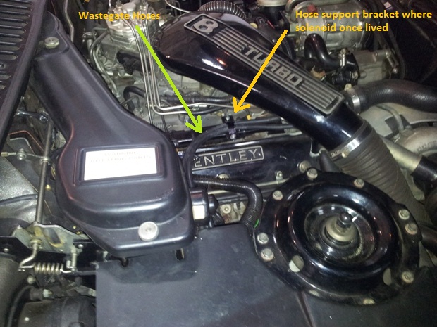
Ok, Now I have fitted a Hella ceramic solid state relay and relocated the solenoid to a cooler place. The extra length of hose seems to have no effect. Given that three out of three here have been experiencing problems with the boost solenoids, it has to be a good thing. The Saab guys told me that they have never sold a boost solenoid as they are extremely reliable. That has to be a clue to thye location needing to be a bit cool. Note that I fitted a Saab solenoid valve this time: exact replacement but in a different colour. Hidden under the relay cover, who cares ? Also note that I have attached a short hose to the solenoid exhaust port so that it vents into the engine bay and not all over the Motronic. RT. Underbonnet showing boost hoses 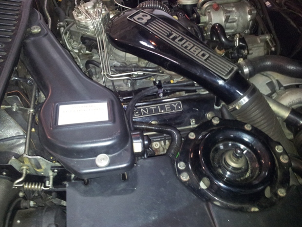 Solid State Relay  Repositioned Boost Solenoid 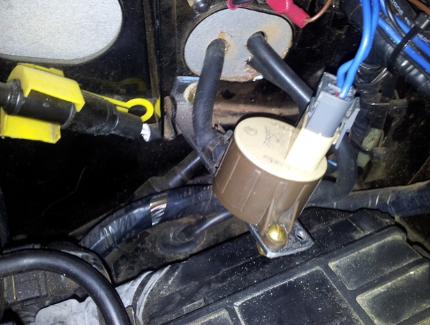 | ||||
Richard Treacy Grand Master Username: richard_treacy Post Number: 2617 Registered: 4-2003 |
 | ||||
James Feller Prolific User Username: james_feller Post Number: 200 Registered: 5-2008 |
nothing like a cool boost huh RT... frankly im going to forward all my speeding tickets to you Richard as this resurrected boost not only is amusing and highly addictive but makes me want to drive the car a lot more and at VERY illegal speeds...will you come visit me in gaol? Serious now, New TB solenoid coming on friday for my car to ensure absolute reliable 9psi and 600mbars each and everytime I want it! RT and I will post picks of this. We intend to do the above boost solenoid relocation on my 89 Turbo RL soon to ensure its always kept cool. As we both suspected a few weeks ago re the 'occasional non engagement' is more than likley down to the the things being cooked over the years noting the ridiculous place Crewe installed them originally...new one being fitted to motronic position should cure it. Frankly why the motronic ECU is located in the engine bay is silly too! in my 86 FI Spirit its Jettronic ECU is under the drivers knee roll, safe, dry and a heck of a lot cooler place than the bloody engine bay.... J | ||||
James Feller Prolific User Username: james_feller Post Number: 202 Registered: 5-2008 |
btw...great looking modifications RT! neat, smart and protected. What it should have been originally when paying $700K for the bloody things!!! hmmm....though I must confess prefer "black" colour rather than brown..... I know im just being picky now..... lol. see you later. J | ||||
Richard Treacy Grand Master Username: richard_treacy Post Number: 2619 Registered: 4-2003 |
Thanks James. Perhaps I'll hit it with some black paint. The last laugh will be on you when your new one turns up and it's.....Brown. | ||||
James Feller Prolific User Username: james_feller Post Number: 203 Registered: 5-2008 |
LOL...im laughing!! its black!!! With thanks to RT for today helping me perform the RT boost solenoid relocation and rectification. Boost solenoid is now in a much more sensible place in the motronic compartment, looks original, neat and tidy!! Richard and I were laughing today wondering what people must be thinking about a handsome Green Conti and my Blue Turbo tearing and blasting around the motorways near Mascot with two Bentley mad fellows upfront with cheshire cat grins on their faces!!! resurrected boost is VERY addictive!!    and a few more majestic ones... now to bring on TB!!  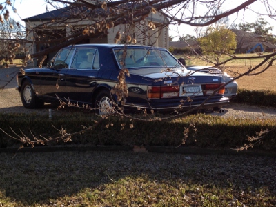  | ||||
Lluís Gimeno-Fabra Prolific User Username: lluís Post Number: 231 Registered: 8-2007 |
And imagine the day that you put a potentiometer in that green wire... ;-) | ||||
Richard Treacy Grand Master Username: richard_treacy Post Number: 2623 Registered: 4-2003 |
Lluis, On whether the boost and transient overboost systems are living up to expectations or not you had better ask James. We twisted a few axles between Sydney's East and the airport today, and I must say that both cars have changed from zippers to barnstormers over the past few weeks. We have not finished yet, but James may comment further on progress. RT. | ||||
Lluís Gimeno-Fabra Prolific User Username: lluís Post Number: 232 Registered: 8-2007 |
Hoi gentlemen, It's nice to see that you are Autobahnstorming now. It is indeed addictive, but being relatively easy to try and reversible, the pot modification is really a nice one in case you want to give it a shot. I am however writing on a different pot-topic. Being Friday and overworked I decided to spent my afternoon with the turbo-guy here going over the information of the Saab APC. He is quite convinced that the forums are right describing empirically the behaviour of the ECU, but wrong in the meaning of the potentiometers, which to his experience should be "proportional", "integral" and "derivative" and that what you do by turning them is to change the respective constants in the control function of the ECU. Eventually the K potentiometer could be the segregation function between acceptable Knock sensor frequencies and not acceptable, but he would be surprised. The meaning of PID controls is beyond my expertise but what I understood it that basically derivative would be changing the slope of the signal reaction, Integral the damping factor and constant the maximum signal level, so boosting slope, max boost and damping of the signal towards it's horizontal max boost asymptote (max boost). As damping includes going "beyond" max boost before stabilising, the behaviour empirically tested in the Saab forums as being "transient" could fit in in with the explanation. I am extremely curious to see what bench testing will provide in your Saab ECU Richard. Tomorrow I am recording the pressure level in the car as I need to go to Schiphol and back and roads are quiet now, I am however confident that 0.6 bars are coming now at 3000 rpm from mid throttle, more on that tomorrow night. See you, Lluís | ||||
Richard Treacy Grand Master Username: richard_treacy Post Number: 2625 Registered: 4-2003 |
Hi Lluis again, To clarify PID (Proportional, Integral, Derivative) controllers that I mentioned very early in these topics to one of your posts: the P Proportional gives a step response to reference (ie demanded boost pressure). The D Derivative pushes a spike when a step change comes along to speed things up, and the I Integral gives rise to zero error once things settle (ie what you ask for is exactly what is achieved when everything is stable). Once I fool around with the Saab ECU which has just arrived I shall confirm all this. If it is really a common-or-garden PID controller with no reference boost pots, then some Saab guys (like yours) are correct and the others just lucky but misguided. RT. | ||||
Richard Treacy Grand Master Username: richard_treacy Post Number: 2626 Registered: 4-2003 |
Mind you, with the boost control bits being pure Bosch stuff developed for Saab, I am almost expecting it to be simpler: The pots F and P on the ECU could mean: F= Führungsgröße (reference maximum boost) and P= Proportionalität (proportional gain.) I shall discover more… RT. | ||||
Lluís Gimeno-Fabra Prolific User Username: lluís Post Number: 235 Registered: 8-2007 |
Richard, Are you using generic fuel hoses to route the pressure? I took the bloody intake apart (which helped me clean a number of things and hopefully sort my oil leak) and I will hopefully relocate the solenoid this week. I will post pictures, but I plan to do a "boost control panel" in the engine bay, with the potentiometer, the two solenoids (transient and stable) and the relays. All nice with a "don't touch" label for Brabo. Best regards, Lluís Best regards, Lluís | ||||
Richard Treacy Grand Master Username: richard_treacy Post Number: 2632 Registered: 4-2003 |
Lluis, I used 1/4“ (6.5mm) vacuum/low air pressure hoses (cost at the parts shop or swimming pool shop was about than €4/metre). The inside and outside diameters are identical to the old brittle hoses. Fuel hose is normally reinforced and needs larger and uglier hose clips. It is not a critical issue as the pressures are relatively low. Underbonnet boost panel. Nice. In my transient boost module I can do the same but must first remove its lid to access the pots and other electronic adjustments. It has several switches to move it into simulation mode so I may set the values statically one by one. RT. ps: best put a Don't Copy label on for Brabo. | ||||
Lluís Gimeno-Fabra Prolific User Username: lluís Post Number: 236 Registered: 8-2007 |
Richard, this is the most complete description of the APC that I have found http://www.900aero.com/ I recommend the simulation part on the page with a description of the response of each pot. See you, Lluís | ||||
Lluís Gimeno-Fabra Prolific User Username: lluís Post Number: 237 Registered: 8-2007 |
Hi all, Just a little hand still: Yesterday I reassembled my manifold and boost control system and forgot to not in which sense do the arrows of the non return valve from the plenum to the dump-valve goes. Logic tells me it should be from dump-valve to plenum, so as to let depression actuate on the dump-valve but no boost. Can you please confirm? Lluís | ||||
Richard Treacy Grand Master Username: richard_treacy Post Number: 2636 Registered: 4-2003 |
Lluis, I think that’s the wrong way. The arrow should point to the dump valve. There is one hose from the plenum which splits into two just before the dump valve. One part goes direct to the dump valve pipe: that is the pipe at the bottom of the dump valve furthest from the mounting bracket. The other goes to the pipe close3st to the mounting bracket and the action: it goes through the one-way valve to the dump valve with air flow only able to blow the diaphragm shut quickly when the boost comes on. That reduces turbo lag. Correct me if I am wrong someone please !! RT. | ||||
Lluís Gimeno-Fabra Prolific User Username: lluís Post Number: 239 Registered: 8-2007 |
Ok, So according to this it's the small pipe that connects to the dump valve body through a the soldered elbow which open the dump-valve when vacuum is applied, and it's the other one with the one-way valve that applied pressure to close it shut. I really need IETIS and to find time to buy a lap-top. | ||||
Richard Treacy Grand Master Username: richard_treacy Post Number: 2639 Registered: 4-2003 |
Almost correct but not quite, otherwise there would be two one-way valves. I think it is mainly to speed up the opening of the dump valve when the throttle is closed suddenly. That is to do the job of a blowoff valve without that horrible drama you hear with Evos and WRXs. The effective diaphragm area on one side is smaller than on the other. If pressure or vacuum is applied to both sides it will move but at a regular pace. If you snap the throttle shut, the one way valve prevents the vacuum from applying on one side of the diaphragm. The result is to open the dump valve pronto before something bursts when the intertia causes a pressure surge. RT. ps IETIS says nothing about all this. | ||||
Richard Treacy Grand Master Username: richard_treacy Post Number: 2640 Registered: 4-2003 |
Lluis, Here is a picture I just took from my Conti R which confirms my thoughts. OK it’s an earlier setup than yours, but the one-way valve has the same function and most of the peripheral parts are the same. Note the direction of the arrow towards the dump valve. I wish that IETIS or at least one other manual would tell us this, but there is never a mention except that the valve exists. RT. pps: on Zytek cars, the Goldie that James and I refer to on his car - the transient boost solenoid - is superseded by a second Saab solenoid. Double trouble when hot ! 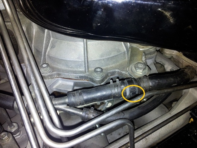 | ||||
Richard Treacy Grand Master Username: richard_treacy Post Number: 2642 Registered: 4-2003 |
pps: the dump valve is double-actuated as noted beforehand. In the picture above you can see clearly where the plenum pressure is split (on the left) and then the one-way valve interposed into one hose only. The dump valve is double-actuated (two hoses) because it is modulating the pressure above the butterfly whenever there is manifold-plenum depression. It is not simply open or shut. That gives the marvellous part-throttle response that you and James have rediscovered, and indeed what prompted me to find out why my Conti R was so mediocre compared to my Turbo R when I first explored the Conti. However, once under boost, the dump valve is completely shut. The double-activation gives the opportunity also, thanks to the one-way valve, to slam it open when full manifold depression suddenly kicks in if you drop the throttle in a hurry. RT. | ||||
Lluís Gimeno-Fabra Prolific User Username: lluís Post Number: 240 Registered: 8-2007 |
Thanks so much. A good book ŕ la Haynes would be useful indeed, but IETIS is better than nothing... The hoses (all of the hoses that never get changed, meaning oil vapour from the filler, turbo, etc...) were ROCK solid and many broke when I tried to remove them. I can't wait to drive the car tomorrow, as I exercised the transient boost solenoid (which now clicks like a master) and have all flow going nicely through my new pipes. In parallel I am starting to build the boost adjustment and activation module (as I call it). Best regards, Lluís | ||||
Richard Treacy Grand Master Username: richard_treacy Post Number: 2643 Registered: 4-2003 |
Lluís, Yes, the hoses on even the most well-cared-for cars seem rock hard and are pleasantly replaced. Now. That transient boost solenoid. Was it sticky before exercising it ? If so, maybe you are in for some more fun on the test drive. James has a brand-new one to fit on Friday. He suspects that his TB works once in a hundred asks at the moment. Does this imply that if his old one is sticky, then he is in for an even faster moonshot after he fits it ? RT. | ||||
Richard Treacy Grand Master Username: richard_treacy Post Number: 2644 Registered: 4-2003 |
ps: if so, then the TB solenoid valve is also immediately banished to a cool place. | ||||
Lluís Gimeno-Fabra Prolific User Username: lluís Post Number: 241 Registered: 8-2007 |
Hi again, My TB solenoid was clicking with a damped click, after soaking in WD40 and exercise it's back to a healthy click, much the same as with the boost solenoid. I am also of the opinion that a cool place will help, but the culprit of the problem is the oil in the boost air, I have seen it with my own two eyes, as I purposefully re-dismantled the solenoid again this week end: there was oil inside the cylinder and when burned by temperature it blocks the valve. Oil vapour in the boost air is quite normal, my car does not smoke nor use any significant amount of oil (other than the very recent minor leakage) and the turbine does not have any significant play, but being bronze-bushed it's levitates in oil, so there is just the thinnest of the layers of oil that pollutes the air, and the solenoid is about the only place to condensate where it's effects are felt. AS said, tomorrow I am getting a 200K pot to have more play, and this week end I am doing the boost rack with all the goodies, so that it is nice and cold. A thing I will also learn to do, when putting the key in the slot and turning, hear for the click, then depress the throttle till 80% and hear the TB click. And the party can start... See you, Lluís | ||||
James Feller Prolific User Username: james_feller Post Number: 205 Registered: 5-2008 |
ok!!! thats very interesting Lluis listening for the double click!! You are becoming just as addicted to this as Richard and myself. I will try the double click later and see if I can hear it. As RT mentions, I suspect the TB works very occasionally and not reliably at all. I have a new one to install and hopefully RT and I will be in for a big treat on friday. Interesting too Lluis your comments about the oil vapour build up in the TB solenoid, this would make sense then that over time and with little use it eventually just ceases to work. As the TB on my car is very rarely called on that would seem to make sense. Rarely if ever is the car doing 3-3500rpm, around town as we know they woofle about at just over 1000-1500 at best, crusing at Aussie motorway speeds is just as lazy for these cars 2300-2500rpms. Ive had the Turbo for about 6 years now and while a do extended freeway drives, the pathetic speed limits in Australia of 110klms means that i rarely extend the cruising RPMS much beyond 2400 rpms. Yes when over taking at high speed the needle shoots skyward to these TB ranges and with all the recent work RT and I have done re electrical boost enhancement, its only while up at this speed and Rpms I sometimes feel a magical and very definate shove at 3000-3500 and the car just accelerates like the wind. Never fails to make me smile!!! But its not always the case in these instances, this is why I will replace Goldie so we have a clean and new TB solenoid to test. RT, I think yes we do look at moving goldie to a cooler place as well...but first lets see if we can get the recalcitrant little bugger working everytime and reliably!! Im very keen to finish all of these rectifications and enjoy what my car is easily capable of again!!! more to come and photos too boys. RT is right Im enjoying the vastly increased mid range torque again thats been restored thanks to a few new solenoids and relays....never ceases to amaze me at whats been achieved with so little....LLuis need a full report on your findings too, in between us all giggling like naughty school boys with our Turbo toys...  J | ||||
Richard Treacy Grand Master Username: richard_treacy Post Number: 2646 Registered: 4-2003 |
One interesting point about installing solenoid valves: on Saabs, the outlet port is connected to a depression, exhausting just before the air flow sensor. That helps them along a bit as the depression assists the electrical action in opening the valve. On ours they simply vent to atmosphere even though the outlet is a barb made for the Saab hose. It would be a very simple change to connect a hose in a similar manner on cars with the Saab solenoid like ours. Incidentally, James and I have connected a short exhaust hose so that the valve vents outside the Motronic cubicle. When I opened my solenoid valve it was clean and not at all oily. Admittedly I had cleaned it up a bit. However, it all adds up: oil, grime, old plastic and heat. RT. | ||||
Lluís Gimeno-Fabra Prolific User Username: lluís Post Number: 243 Registered: 8-2007 |
Hi, No grin here today but grim, due to my leakage grrr. I also think that constant blowing and hardly any activation under constant heat, so that residue becomes solid ends up killing the solenoid activation. The Saab solution is so much more elegant, with the tubes discharging into the turbine inlet... maybe next modificatio. But first I have a leak to deal with. Sh****t. Leaking regards, Lluís | ||||
Lluís Gimeno-Fabra Prolific User Username: lluís Post Number: 246 Registered: 8-2007 |
Hi all, Inspection of the oil filler cap revealed a very hard cork seal which was literally breaking on my fingers when removed. It was immediately replaced (Brabo had one). The breather overhaul has certainly had an effect as well, as I am back to two drops of oil on the floor... let us see and hope, next week end I am in the UK and will drive a 1000Km. I am back into business with boost. I added an in-line 100K resistor to the pot active line to see what the next attenuation series will do to boost, but I will try carefully. Before Friday an electronics guy from the office will meet me and he will produce a PC based, serial port, voltage corrector, so that I can artificially create as APT output voltage from the linear input that the APT produces by introducing a non-linear attenuation, this will allow me to boost at lower rpm: the pot solution is linear, which is very nice, but I want more boost at 2000rpm. I also finally got a micro-laptop, IETIS working and I am looking for a catalog system, that I can plug to Mastercheck outputs for convenience and record simultaneously tps, boost, airflow, etc.... By the way, I scared the crap out of myself this morning, my dear Continental decided to idle at 2500 for a few seconds whilst in a 30Km/h area: or the throttle got slightly stuck, or Motronic tried to kill me after being dismantled for a few days. 100 Km on the situation is not repeated, but I had a moment of annoyance, any ideas of what may have caused this? Best regards, Lluís after Any further ideas on this well come | ||||
Lluís Gimeno-Fabra Prolific User Username: lluís Post Number: 247 Registered: 8-2007 |
Hi again, Hi Richard, Your comments are taken very seriously this side of the globe... please do not hesitate to comment on my comments below: The pot in my present set (100K ground throrugh 100 K) attenuates voltage to 2.23V (from the 2.35 orginal) in its maximum full wind position. I have measured boost and at 100K the boost control system controls boost to a stable 380-390 mBar (which is about 3 V APT voltage on the modified setting) at 3500rpm+ without TB, no knock what so ever, perfectly linear behaviour up to 4200rpm -ambient is 20°C- This evening I will make a full plot of pressure vs voltage for both settings and try to post it. Unfortunately I am still waiting to get a very exact manometer, so please do take my findings with a pinch of salt. See you, Lluís | ||||
Richard Treacy Grand Master Username: richard_treacy Post Number: 2654 Registered: 4-2003 |
Thanks, Lluís, The post following this introduction seems to have fallen out. Lucky, because there was a fundamental mistake in it which I have now corrected. The reason that you are having such small attenuation (ie not reducing the signal to 50%) is that the 100k resistor and 100k pot have values which are too large. Two 50ks would be far better, but you may safely go down to two 27ks if need be. It is explained below: the resistors sink current from a source of 5V with 100k internal impedance. Hence, the value of your pot-resistor pair is too close to the source impedance. That is why a pair of 50k resistor/pot will do a better job. If still not enough, go to 27ks. Note that with a pair of 50k resistances the source impedance is 25k ie with the pot set to minimum for the maximum boost, or a few ohms with the pot wound up fully for standard boost characteristics. My TB system works fine with, effectively, a pair of 57k resistors. Reposting with correction:
Lluís, I must comment here, as a series resistor will be detrimental. It will send the signal at the boost controller to an even HIGHER level than it is and effectively make the controller work on no boost all the time. In fact, the signal would probably sit at 4V all the time regardless of what goes on pressure-wise. Other strange effects could also occur if safety checks in the various ECUs detect excessively incompatible signals. For a start, the boost solenoid will probably clatter as soon as you turn on the ignition. In other words, a series resistor will effectively stop regular boost altogether. Furthermore, I have held back until now on the value of your potentiometer: it is too high and is not attenuating the APT signal accurately. I know that I recommended the value, but tests have shown it inappropriate. I suggest that you address the potentiometer circuit rather than doing anything else. To explain, I have jotted down the equivalent circuit of the boost controller input. It is made to be fail-safe in case a connection goes bad. In that case, the boost input goes to 5V, so the boost controller shuts down boost altogether. The boost controller has an input impedance of around 100k, and the APT sinks current to ground with a much lower impedance to give rise to the applied APT voltage. A higher impedance at the APT allows the voltage at the boost controller to float higher, not lower as you are seeking. The pot you are using has an impedance which is far too high. When wound to full attenuation, it will not be doing 50%, maybe more like 25%. In fact, in the higher ranges, when you first wind the pot from its top position, the voltage seen by the boost controller will be increased, causing the controller to reduce boost: the opposite of what you are seeking. As a compromise, I would recommend a pot with maximum 50k, with a 50k resistor to limit the attenuation as shown below. That will give an effective input impedance of less than 100K and an output impedance of less than 25k. That will be safe, but I considered loading the APT by going down to a 27K resistor and 27K pot too. The circuit below will give a maximum attenuation of 50%. At that value of 50%, very roughly, the boost controller would see a voltage of less than 2,5V indicating almost no boost when the turbocharger is actually running at 1000mBar boost. That is already out of range, and the transmission may even misbehave as it shares the signal, so I suggest you go no further. By the way, I confirmed this behaviour on my car early during the design of my TB ECU. Your electronics guy will understand my comments instantly. RT. 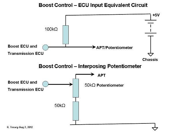 | ||||
Lluís Gimeno-Fabra Prolific User Username: lluís Post Number: 248 Registered: 8-2007 |
Voilŕ, It's understood. I have not interposed the resistor and driven the car. I am quite happy with the car safely pottering around at 380 MBar, which is more than original, but will try immediately the 57+57 option or even 27+27, my objective would be 500MBar and then transient kick in at full TPS. See you, Lluís | ||||
Lluís Gimeno-Fabra Prolific User Username: lluís Post Number: 251 Registered: 8-2007 |
Can somebody correct my thoughts below: I am quite convinced that Motronic M3.3 knows nothing about intake pressure, it only and strictly reads airflow (in respect to air magnitudes -in addition to rpm, TPS, etc...-). I have tried to find a connection between motronic and the APT and I am so far un successful, IETIS EMS description only discusses pressure in connection with the boost ECU. Do correct me in case that I am wrong. Furthermore I read in the "insight to boost controlled systems" in RR technical info, that L and K jetronic ECU had an earlier advanced setting for turbocharged cars, which would be the reason for reduced boost. In my opinion, this was however prior to close-loop lambda control system, as in Motronic, wherein the advances curve is not preset differently for cat and non-cat cars and wherein the the main reason would be to stay in close loop until 3000rpm (with reduced boost) for emissions (as described in IETIS). This has certainly positive implications in respect to how far the turbo setting can be fiddled with, I hope to be able to set it up at 500MBar in non-transient operation, but I want to be sure that fueling can cope. Best regards, Lluís | ||||
Richard Treacy Grand Master Username: richard_treacy Post Number: 2656 Registered: 4-2003 |
Hi Lluís, In IETIS you will find the ATP – MAP for the Motronic. It is Item 33 in the attached wiring diagramme and Item 21 in the component location diagramme. It is needed especially under boost, when the air flow meter is measuring the flow of dense, pressurised air rather than air flowing at almost atmospheric pressure: the pressure loss, giving only a slight depression at the air flow meter, is mainly the air cleaner system when there is no boost. With boost, the Motronic compensates for the denser air. RT. Click on icons to view files.
| ||||
Lluís Gimeno-Fabra Prolific User Username: lluís Post Number: 253 Registered: 8-2007 |
Hi all, For those running Zytek EMS (post 1996) please see what the set up of the twin boost solenoids looks like. This is the Continental R of my friend with the top intercooler water-air. I made close inspection of his car today which proved also to me how much oil the charger discharges into the intake. Richard: in case that you are asking yourself why and how did I kill my AFM, the answer is that once I had my intake dismantled I started cleaning everything, some elements with great success, such as the very dirty ISCV... some with less, like one of the ceramic substrates of the hot film AFM. Idel however is magical now :*) Not happy, but at least hardly any leak now and beautifully cleaned intake with all new boost hoses... Hopefully on Tuesday a new lambda sonde and a new AFM. Lluís  | ||||
Michael Hicks Frequent User Username: bentleyman22 Post Number: 55 Registered: 12-2011 |
Look Like my RT Ha Ha it is the same | ||||
Lluís Gimeno-Fabra Prolific User Username: lluís Post Number: 255 Registered: 8-2007 |
Hi Richard and all others, but in particular Richard, We have completely different Motronic set ups, in my case it's the 88 pin, with a rather different wiring. I will try to post this evening the image of the wiring. By the way, would you be in need of Bosch part numbers: Idle Speed 0280140550 AFM 0280217002 Lambda 0258003230 My car runs now beautifully, turbo operates perfectly and no leakage almost... I also want to confirm that no potentiometer means exactly 330 mBar pressure, with pot at 100 it's 390 mBar and when I am back from holiday I will try the set up with 27+27 K Ohms. THANKS to all for the support updating and servicing my boost control system. Best regards, Lluís | ||||
Richard Treacy Grand Master Username: richard_treacy Post Number: 2657 Registered: 4-2003 |
Hi Lluís, I am aware that your Motronic is quite different albeit of the same family. For a start, our early cars have twin distributors, whereas yours has none, just 8 amplifiers and coils. However, surely it has a MAP input ? I’ll dig out the schematics. Good to hear of the progress ! RT. | ||||
Richard Treacy Grand Master Username: richard_treacy Post Number: 2658 Registered: 4-2003 |
Hi Lluís, I see what you mean. The later cars have an air mass flow hot wire sensor, which presumably takes the pressure into account. Hence no reference to a MAP sensor for the Motronic. A simple air flow sensor as on earlier systems does not compensate for air pressure, and presumably needs the MAP sensor to calculate mass flow ! RT. | ||||
Lluís Gimeno-Fabra Prolific User Username: lluís Post Number: 257 Registered: 8-2007 |
Voilŕ That is what I meant, no APT input for Motronic 3.3. I also wanted to tell the list about my week fun with my AFM after breaking it... Friday I called my favourite specialist to get one AFM, thinking that this would be the couple-of-hundred-€ idiocy of the month... and was paralised when I heard "1100€ but no AFM deliverable". Bentley will only offer some magical conversion kit: an AFM to MAP (pressure) conversion chip, which costs 55 cents + programming... but for 1100€. The modification is not silly, but precisely the opposite of what we want to increase turbo pressure. Bentley likes it for a number of reasons, price, but also a robust design with one single sensor, as followed by many modern makers. Then I start looking around to find one AFM... mine is a Bosch but with no part number. More research reveals it as a hot film sensor, very precise but very fragile and I broke it (or possible simply helped breaking it) by brushing it with propanol. Mind you it is considered considered troublesome for this reason in many GM applications (including Volvo and Opel). Now guess what the fun part is, Bosch only produces two AFM and that the correction for total flow-voltage is made on the basis of increasing the air pipe diameter around the AFM probe... I finally find that aforementioned part number is the most promising option, but Bosch only offers two sensors, despite a myriad reference numbers, one for horizontal installation,one for vertical (more or less), see here http://www.bosch.com.au/content/language1/downloads/sensors_airmass.pdf Bingo, you can even have it on twin-hot wire arrangement on a micro-chip plate as conversion in case that you don't want the hot film unit (which is perfect other than for fragility. Installed it, drove it, happy and with some change from 1100€ left. After trying all set-ups I plan to take a day off and go to a good specialist and do a full rolling road tuning session. My car worked well before, but I am marvelled at how it drives now but want to be 99.99% sure of correct AFR before German driving. Lluís | ||||
James Feller Prolific User Username: james_feller Post Number: 209 Registered: 5-2008 |
KNOCK KNOCK KNOCKING ON HEAVENS door....or KNOCK likely.....hmmmm bloody KNOCK SENSORS...check them and CLEAN them! they can upset alot of good work and be entirely a drudge to good time!!! | ||||
Richard Treacy Grand Master Username: richard_treacy Post Number: 2659 Registered: 4-2003 |
Bruised arms and fingers from removing, cleaning and recommissioning both KSs tonight independently. Yip. Horrible stuff. Luckily I have a result. WTS. | ||||
Mark Luft Experienced User Username: bentleyman1993 Post Number: 11 Registered: 10-2016 |
I have a 1993 Turbo R which I believe does not have transient boost. Will these mods work on mine? I'd LOVE more boost. Thanking everyone involved! Mark | ||||
Lluís Gimeno-Fabra Grand Master Username: lluís Post Number: 415 Registered: 8-2007 |
Yes indeed, all of them work, you just need to make sure that the knowck sensors are fine and increase the boost pressure to close to 0.6 bar | ||||
Omar M. Shams Grand Master Username: omar Post Number: 1088 Registered: 4-2009 |
Dear LLuis, in a nutshell then - how difficult is the mod to execute? any idea how long the change will take from start to finish? Thanks Omar | ||||
Pete's Carstar Unregistered guest |
can anyone tell me how many volts are supplied to the solenoid. (Message approved by david_gore) | ||||
Richard Treacy Grand Master Username: richard_treacy Post Number: 3273 Registered: 4-2003 |
Gosh, this tread goes back to 2012. As explained, there should be battery voltage less about 1V with the motor stopped and the ignition turned on (maybe 13 volts). Touch the brake pedal and it should go to zero and the solenoid should click audibly shut. Most are hovering around 6-10V and usually not high enough to keep the wastegate open, hence the advantage of fitting a solid-state relay and amplifier as explained above in this thread. A standard electromechanical relay will not do as they are too slow to follow the PWM signal during partial wastegate inhibiting at maybe 40Hz. The relay will de-stress the boost controller output driver and the metres of thin cables from it to the wastegate control solenoid and extend the useful life by a few decades at least. As eluded to earlier, attending to tired boost control wiring at the knock sensors and applying the solid state relay could quickly find you another 150HP with ease. RT. | ||||
michael vass Frequent User Username: mikebentleyturbo2 Post Number: 580 Registered: 07-2015 |
Hi lluis ,RT and all I wonder if fitting a capacitor after the pot to ground would give a delay and act like a transient boost? 1mf would give about 1sec before the voltage signal rose to the ecu. What do you think? Mike |