| Author | Message | |||
Richard Treacy Grand Master Username: richard_treacy Post Number: 2562 Registered: 4-2003 |
I felt that my 1993 Continental R (KE3-Motronic) didnít have the urge of my Turbo R, so I have undertaken some investigation before going the full hog and tweaking the transient boost. Sometimes it seemed to give the extra zap I expected, but only very occasionally. I soon recognised that the Cat cars like my Conti R have a lower continuous boost setting than non-cat cars like my Turbo R. In fact, transient boost on a cat car three seconds after planting the foot is almost identical to full continuous boost on a non-cat. So far so good, the Conti should be a bit slower. But it still usually felt, dare I say it, er, gutless. To check it all out I bought a boost test gauge, one which shows vacuum and boost in millibar (mBar). Surprise surprise, the boost topped out at 160mBar, a far cry from the 320mBar it was supposed to be, let alone the 600mBar peak on Transient Boost or the 430mBar of my Turbo R. Hell, the wastegate was always opened by the turbine to its base level of 160mBar !! Next, test the boost control relay with 12V. Fine. A quick run at 600mBar and WOW. A real tyreshredder at last. Yip, the Turbo and wastegate are up to it. Next checked the ECU. Working fine. BUT when activated, the boost solenoid was down to 10V, not unreasonable for a solid-state driver, but the solenoid was not picking up with a healthy clunk. I exercised it about 50 times with 12V and it started to work occasionally. Darn it, better but intermittent. The thing must have been pottering around to much with the boost never demanded for too long. No messing around now, I simply fitted a standard Bosch relay (the same relay as all the other relays in these cars) in the circuit to give it the full 12V when energised and went for a spin. 340mBar straight away. So, that explains why so many Turbo Rs I drive seem gutless as the boost control solenoids have become lazy with disuse. If your Turbo Bentley is a bit less gutsy than you think it should be, this may be the answer and cure. Give it a thrash more often. Or best fit a helper relay so that it will always respond when asked to do so. RT. | |||
LluÌs Gimeno-Fabra Prolific User Username: lluÌs Post Number: 191 Registered: 8-2007 |
Hi Richard, Let me see, you fitted a 12V relay prior to be boost solenoid? I thought the solenoid is activated several times per second, to control the waste gate. Will the relay last very long? What I was thinking was to put a frequency controller in line with the solenoid signal with a controller in the cabin, so as to allow re-programming of the boost signal. What do you think? LluÌs | |||
Omar M. Shams Prolific User Username: omar Post Number: 258 Registered: 4-2009 |
Dear Richard, Where is the boost solenoid located on the 91 Turbo Rs? I would like to check mine out. Also how do you check to see if it is functioning correctly? Thanks Omar | |||
Richard Treacy Grand Master Username: richard_treacy Post Number: 2563 Registered: 4-2003 |
Lluis, Yes, a standard 12V interposing relay. The solenoid itself is a simple electromechanical device and far slower than the relay. At a guess, it can switch in and out at down to 200mSec at best. The relay is rated at 30 Amps DC and should last fine given its low duty, although it pulses at about Ω second intervals at times I assume. I shall keep an eye on it, and fit a solid state relay if need be. The trouble is then that any voltage drop across a solid state relay seems to worry the boost solenoid. Omar, this is the boost relay on your RL. It should click on with a thunk when you turn on the ignition, and clunk out if you touch the brake pedal. That is a good first test. Then remove the hoses and check that it opens by blowing through it. Lastly, hook up a test lamp to see it flicker when you drive hard. Alternatively, a boost test gauge costs less than 50 bucks and will tell all. The attached chart shows the tree levels of boost curves: A: Non-cat cars B. Cat cars C. Wastegate permanently energised (boost solenoid valve inoperative): 162 mBar  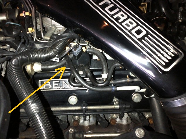 | |||
Richard Treacy Grand Master Username: richard_treacy Post Number: 2564 Registered: 4-2003 |
We just tested a 1989 Turbo R with the pressure gauge. Statically, the solenoid appeared to function as described above, clicking in and out with the brake pedal. We took it for a spin and saw only 160mBar. The solenoid was no longer functioning when we stopped to check it. Testing with the multimeter showed that the output was 10.5V on no load, but dropped to less than 5V when loaded by the solenoid. It was incapable of driving a test lamp. After a rest, the boost functioned up to the desired 320mBar boost just once then packed up again. Weíll try a relay on that car tonight. On my Conti R there were 10V without the new relay whilst this one dropped even lower when hot, all suggesting that the control electronics are systematically slightly under rated for the application. I am guessing that a combination of age and heat causes the ECU output capacity to degrade over time. At least on both cars the ECUs seem to function correctly, and I hope that the relay will be a proper upgrade for all these cars. However, I shall look for an alternative suitably fast solid state relay to be on the safe side. RT. | |||
LluÌs Gimeno-Fabra Prolific User Username: lluÌs Post Number: 194 Registered: 8-2007 |
Richard, Where do you take the 12V in the engine bay so that it looks neat, without too many cables? Best regards, LluÌs | |||
Richard Treacy Grand Master Username: richard_treacy Post Number: 2565 Registered: 4-2003 |
Lluis, It's not worth a photo as there is nothing to see unless you would like me to remove the cover. I mounted the new relay under the cover for the Motronic and the wiper & starter relays. It is all quite invisible, and I put heatshrink over all the wires. I put it outboard from the relays at the rear of the relay compartment, then spliced a wire from the starter relay +12V lead. The four wires to the boost solenoid area are tucked into the existing flexible conduit. Then I removed the short section from the boost solenoid to the engine loom nearby and cut off that awful original connector from the engine loom as they are not particularly reliable (as I found with the TPS). Fitting standard automotive spade plugs and sockets to the short section which plugs into the solenoid and to the wires (near the boost solenoid) from the ECU, the relay is energised by the two wires from the boost ECU and the power output from the relay energises the boost solenoid. The only other connection is an earthing lug connected to the relay mounting socket retaining nut and bolt. Incidentally I have found a few solid state relays, the best probably being a plug-in Hella H41773001 Solid State Ceramic 32 Amp SPST Mini Relay RT. | |||
Richard Treacy Grand Master Username: richard_treacy Post Number: 2567 Registered: 4-2003 |
Lluis, We had some success with the í89 today, but not as complete as on my Conti. Sometimes it reacts fully but not always, so I am just hoping that the ECU is not kaputt. When it does its full base Turbo bit it is impressive, and that is more than it did before. When we tried it at 600mBar unlimited, My Goodness !!! In any case I have ordered a few Hella solid-state relays on your prompt regarding switching speed and reliability, and just maybe that will be a more final fix. If not up to scratch, I shall make a few MOSFET modules myself and try them out. Next comes my bespoke TB kit. Very promising. Now, shall I tweak the dump valve to 800mBar and trust the knock sensors ? Yip, I think so. RT. | |||
Udo Hoffmüller Frequent User Username: udo Post Number: 87 Registered: 2-2008 |
A boost test gauge may be fine and easy, but it is easy to test the pressure with the voltmeter. In the compartment where the engineECU is located there is the plug connecting the two PTA, one of them is sending the volt data to the turboECU. Connect the voltmeter and read - ignition switched on, but engine not runnung: about 2,3V (depending on weather conditions a little bit), this means 0 mbar of boost - every 100mb cause 0,25V For my test purposes this is enough. With some experience one knows that 2,3 V is 0 boost 2,55 V is 100 mbar 2,8 V is 200 mbar 3,05 V is 300 mbar 3,3 V is 400 mar and the other values in between The formula is: p = (u +0,2) * 400 resp. u= p/400 -0,2 with p = pressure and u = tension, using V and mbar. With 1000 mbar from normal weather conditions you get u = 1000/400 - 0,2 and that is 2,5 (V) A reading of 3,25 V means p = (3,25 + 0,2) * 400 and that is 380, of course you must rest the ambient pressure of 1000 mb or whatever maybe your weather. For my test purposes this is enough. Sometimes I have the voltmeter installed inside the car just to see what is happening while accelerating. Just an idea. Regards - Udo | |||
Omar M. Shams Prolific User Username: omar Post Number: 259 Registered: 4-2009 |
Dear Richard, Thanks for the photo. On my 91 RL, the solenoid looks different and is orientated at 90 degrees to yours. How can I bypass its function to get full boost to test my air system to see if I get any more than 3 psia? Right now all I can get is 3.5psia at best. I wonder if this solenoid is a contributor to my low performance. I have a permanent guage installed in the cab to monitor boost pressure. If the bypass will give me any more than 5psia I will focus on replacing this solenoid. Thanks Omar | |||
LluÌs Gimeno-Fabra Prolific User Username: lluÌs Post Number: 195 Registered: 8-2007 |
Mastercheck has an active pin with boos in the cabin already, it's what I use to check the boost level. It's pin S or T, I don't know by hard, but the voltage readings are identical to those of Udo. Best regards, LluÌs | |||
LluÌs Gimeno-Fabra Prolific User Username: lluÌs Post Number: 196 Registered: 8-2007 |
Would somebody ever feel the need to add an aftermarket boost control system, you have an easy installation next to the Mastercheck plug, with all the signals that even the most complete modern BCS can need, this includes in one spot gearbox signal, airflow, TPS, boost pressure and road speed, all nicely trimmed to 5 volt... (boost gives 5 volts for 2 bar total... so 1 bar boost). You would jut need to wire the boost control solenoid to the new ECU. BUT, I must say that to raise boost I would very much rather leave the system as it is, and put a piggy box in line to trim the square signal to the boost solenoid. I am therefore avidly following this threat to see how Richard modifies the thing. Boost regards, LluÌs | |||
Stefan Morley Grand Master Username: myupctoys Post Number: 356 Registered: 7-2009 |
Hi Guys, Before getting too far into it, boost is all well and good but make sure the AFR is correct. There may be a very good reason cars in assorted conditions are not performing as one might hope beyond the boost. A band aid might not be the best without being sure of the rest of the system. Boost without AFR feedback under full fury is a potential for disaster especially if lean. The electrical output to the solanoid. It's a perfectly valid state of affairs to but a varibale duty cycle to a solanoid to hold the solanoid in a partially open state. As in the case or trying to regulate pressure. Naturally if the solanoid gets sticky, spring gets weaker, the supply drops over the years with incresing resistance in the connections the expected amount of power delivered to the solanoid will change. Food for thought. Few observations on my car when I was fault finding and rebuilding the turbo. 88 Turbo R. My Boost control ECU regulates the pressure to 3.5PSI. If the wastegete reomved from the equation the system regulates to 5.5>>6PSI via the spring loaded Dump Valve. Still need a new fuel pressure regualtor but it'll get there. Stefan | |||
Richard Treacy Grand Master Username: richard_treacy Post Number: 2568 Registered: 4-2003 |
Omar, Omar. You have EXACTLY the same issue with your car. 3psi / 160 mBar is the level that the boost reaches with the wastegate activated full time (see curve C above). If the solenoid or its driver electronics are dead then thatís what happens: 160Bar maximum. This, I suspect, is chronic on Turbocharged Bentleys !!! Attached is a picture of my (gutsy 440mBar) 1987 Turbo R solenoid valve. Perhaps yours is like this one. As to the pressure signals, sure the APT/MAP 0-5V signals are available and useful. There are two: one for the boost ECVU and one for the fuel injection ECU on cars from 1988 onward (earlier cars have just one). Sadly, both are green/slate wires, and they are often transposed so which is which On later cars, the boost ATP has a green/purple wire on one side of the connector near the Motronic ECU which changes to green/slate on the other side of the connector 6-way. In any case, relying on the signal assumes that the signal is correct, and that is why I have used a dumb pressure gauge on the vacuum-boost tube to see the full result just in cast the APTs are playing up (which mine are not). Important to me is that the knock sensors are fully functional, hence I do not intend to bypass the boost ECU. Rather, working with it I can up the boost in transient with the safety that the knock sensors will always prevent detonation if I go too far. Hence a protected 800mBar would be safe. By tweaking the boost APT signal (i.e. attenuate it transient) is fine as the Motronic system has its own independent and re APT signal unmodified to assure the correct fuel/air mixture under boost, and the Motronic can handle 2 Bar absolute = 1 Bar boost (roughly 5 volts on the APT). Early cars with one APT cannot be tweaked unless an independent APT is fitted to the boost as outlined in the Product Support Information bulletins. Omar, you can easily reach 600mBar by disconnecting the hoses at the boost control solenoid. You will e unprotected from detonation as the knock sensors are then bypassed, but as long as you are using 98RON fuel or higher it is safe. You will then feel one very powerful motor car !! Try it, but only brief. Attached are also the APT signal output calculations. RT.  
| |||
Richard Treacy Grand Master Username: richard_treacy Post Number: 2570 Registered: 4-2003 |
Stefan, I assume that you mean 550-600mBar for the dump valve (9psi). Also, with the wastegate fully connected to the turbine feed line (as when the boost solenoid is deactivated permanently), it regulates mechanically to 3psi no electronics required. That seems to be the chronic problem with so many of these cars RT | |||
Stefan Morley Grand Master Username: myupctoys Post Number: 357 Registered: 7-2009 |
Hi Richard, My dump valve opens at 5.5>>6PSI with the waste gate feed pipe removed from the solenoid. IE no manifold pressure available to open the waste-gate. With it connected a rock steady 3.5PSI regulation. Not to say there isn't an issue, by the sound of it there is, both spring pressure in the dump valve and possible the regulation. But my bigger problem is being way too rich under boost. I had replaced the wastegate solanoid. Couldn't unblock the original with degreaser. Think it was Omar who dissembled his. Not a bad idea but I'd already done the deed. Know what you mean about the 10V but wonder if the intention of variable duty cycle is to get the solaiond to act like a linear actuator against the spring. Not so much about losses in the semiconductor driver. Be nice if there was a spec sheet for assorted models and years. Seems to be a bit of variation and wonder if it's all about wear and tear. Stefan | |||
LluÌs Gimeno-Fabra Prolific User Username: lluÌs Post Number: 197 Registered: 8-2007 |
Hello all, Yes, the variable duty cycle is to have the waste gate acts like a variable actuator, more venting to the atmosphere from the solenoid, more boost... and this is just a matter of frequency of venting. I am ashamed to say that after cleaning the contacts in my boost solenoid my car drives better... Richard, you got it right first time... now the explanation of the behaviour of my car, which was, as you remember as fast as any, yet had a lazy solenoid: My car has transient boost, so as you can see from my other posts, I always said that the Zytek car of my friend drove better mid range but was not faster ultimately... this is because in spite of giving me full 0.67 bar on full throttle... my car was on transient, so the full tire-shredding Armageddon came at full gas, making the car fast but not feeling "light", like my friends Zytek car. Of course, this was because my boost control solenoid was lazy (not dead, but lazy), so I had less urge mid-range. The difference is really noticeable, not just subjective. Like getting wheel-spin on a 3/4 throttle kick-down at 70 Km/h... Mr. Treacy was spot-on getting the contacts clean on the solenoid and I will do the relay modification on Sunday and report. In the things to do list now, I have a variable cycle controller for the square signal to the solenoid, so that I can use all safety measures of the original system whilst trimming boost. I am not an electronics man, so I will look after-market. Removing the second cat, which is legal in this country as long as emissions are fine is also in the things to do list. Last but not least the pre-Zytek twin controller system for engine and boost is a wonderful tuner thing, because as said before, as long as the fuelling system can cope, you can tweak so much in safety... and indeed after-market boost controllers, as good as they might be, they do not have very often knock sensor data... so better stick to original as long as it's working and try to find a way to trim the signal prior to the solenoid. Best regards, LluÌs | |||
Richard Treacy Grand Master Username: richard_treacy Post Number: 2571 Registered: 4-2003 |
Indeed Lluis, The dual APT /MAP system is a dream for tweaking. Even better as you note is the independent boost control with its knock sensor protection. Whatever I do to the boost, the mixture is correct courtesy of the Motronic ECU with its own APT, and safety is assured by the knock sensors in the ECUB. I would be very careful to do any functional mods to the boost downstream of its ECU in fear of overriding the knock sensors. I must agree that mid-range response with the boost solenoid working is a revelation. I shall set my Transient Boost to take charge before kickdown to exploit the wonder of these motors without brutal kickdown. Even if we canít quite match the Zytek until fitting a liquid intercooler, we can surely tweak the systems to out-perform them in every respect other than absolutely flat-out !! I too may delete a Cat or two as we can do that here too within reason. I would like to delete the air pump too, but have not researched the ramifications yet. RT. ps: will you use a solid state relay (SSR) for your boost relay ? Iíll swap my standard relay for a SSR as soon as it arrives. It may be overkill, but I do take your earlier points seriously in this regard. | |||
Richard Treacy Grand Master Username: richard_treacy Post Number: 2575 Registered: 4-2003 |
I used the formula from TSD5000 and rewrote it as: Vo=Vs x (0,005P ñ 0,04) where P is in kPa (101,3 at sea level); Vs (Supply voltage) and Vo (APT/MAP output voltage) are in volts; Vs supply volts nominal = 5,0V. I found a formula close to that of TSD500 in my Bosch literature. I note that your formula is slightly different, and wish to compare sources. RT. | |||
LluÌs Gimeno-Fabra Prolific User Username: lluÌs Post Number: 198 Registered: 8-2007 |
This week-end I was planning to fit a usual Relay and to use a digital oscilloscope to take a look at the frequency of the signal to the solenoid. I think that 10.1 volts is the maximum effective voltage that we get because the pulse may have a relative duration a of ca. 80% at full load (I guess). The solution of fitting a relay I like a lot because the relay works as an amplifier to the signal without varying the rate... I am doing research into a Pulse Width Modulator and/or a "sample and hold" circuit, which would increase pulse duration output by a programmable percentage from a given relative pulse duration input. This means that under "open wastegate" conditions, the signal would be unaltered, so perfectly save. On the other hand, in anything beyond 200mBar, I would add pressure step-wise to the factory settings, so that in non-transient boost I am at 420-500mBar during a longer range, transient at 600MBar would be unchanged. The only killer that there is in this modification is that I do not know (do you?) whether the boost control system is a closed loop one, or in other words, when our ECU sends a pressure signal to the solenoid, what happens when it gets a different one from the MAP??? I think this is easy technically, but I have difficulties finding the hardware (I just took a quick look on google). | |||
Richard Treacy Grand Master Username: richard_treacy Post Number: 2577 Registered: 4-2003 |
Hi Lluis, The boost control is certainly closed-loop, albeit heavily overerdamped. I like your concept regarding PWM, and a few of us on this Forum can collide to find an elegant hardware solution. Perhaps a Chebychev response will be the way to go in terms of response characteristics ??? | |||
LluÌs Gimeno-Fabra Prolific User Username: lluÌs Post Number: 199 Registered: 8-2007 |
This is going to be interesting. In case I hole a piston my wife will kill me and you will hear the screams in Australia... | |||
Richard Treacy Grand Master Username: richard_treacy Post Number: 2579 Registered: 4-2003 |
Lluis, a Hole in One is less likely on these machines than me in the PGA, unless you are on low octane fuel without knock-sensor protection. I am convinced that a 5:1 compression, 1.2Bar boost, liquid intercooler and 800PS is the go. One day ! On TB etc, have you seen: http://www.rrtechnical.info/sz/transientboostkit.pdf This is the transient boost retrofit from Crewe. Also interesting concerning boost ramp-down is this very simple bit on Motronic TB cars:
| |||
LluÌs Gimeno-Fabra Prolific User Username: lluÌs Post Number: 200 Registered: 8-2007 |
Thanks, yes I know it. It's really interesting that they charged 8000Ä (like charging 900Ä for a Sanden compressor, or 590Ä for the plastic PAS reservoir, it's just crazy). I just realized that in some posts there was reference made to the wastegate being only on spring pressure with no boost signal. I think that in our cars (at least in mine) when the solenoid receives no voltage, it connects the boost pressure line to the waste gate actuator line, forcing it to open easily. It's when you are on full boost that you have "only" spring pressure, which actually is enough to shut the wastegate down. The TB kit applies addtional pressure to the back of the wastegate to spool up as fast as possible. Am I wrong? Best regards, LluÌs | |||
Richard Treacy Grand Master Username: richard_treacy Post Number: 2582 Registered: 4-2003 |
Hi again Lluis, I agree. The ever-so-slightly quicker spool-up is the only thing that I can see the revised wastegate and forced closure achieving, with its pressure closing. For that reason I am happy to extend the 600mBar application to compensate. It may not be so fast to reach full boost, but let's see. I have a feeling that the Ä8k kit was not particularly smart and that we can do much better. RT. | |||
LluÌs Gimeno-Fabra Prolific User Username: lluÌs Post Number: 201 Registered: 8-2007 |
Hi again, Would this be adequate as a solid state relay? I am an electronic an-alphabet... http://www.conrad.nl/ce/nl/product/504797/Elek-autolastrelais-ER-70-12V-70W/SHOP_AREA_84267&promotionareaSearchDetail=005 LluÌs | |||
Omar M. Shams Prolific User Username: omar Post Number: 260 Registered: 4-2009 |
Dear Richard, In your link (page 8) you can see that there are both a TB solenoid and a Boost control solenoid on the same image. From what you have explained to me, my boost control solenoid looks just like the TB solenoid on the image. I have not been able to take the RL out yet because the alternator belt is off the car awaiting replacement. When that is done I will try disconnecting the Boost Control Solenoid pipes. When I remove the pipes, should I plug them too for the road test? Thanks Omar | |||
Richard Treacy Grand Master Username: richard_treacy Post Number: 2583 Registered: 4-2003 |
Hi again, Lluis, it MAY be OK, but I can only find the limited data from Conrad. It doesnít list on-voltage drop. Most I found like that one have a 2,3V on-voltage drop which is far too high I believe. However, they are described as direct replacements for automotive use, so they are probably fine with a 0,5V drop or so. Worth a try if you are in a hurry. The ones I have ordered are Hellas. They are actually cheaper at Ä23 or so, and shipping is cheap from the USA. I just found an Amazon link, although I bought mine direct: http://www.amazon.com/HELLA-H41773001-Solid-State-Ceramic/dp/B000VU5FPE H41773001 Solid State Ceramic 32 Amp SPST Mini Relay And have the ideal characteristics. Apart from being fast and having no moving parts, there are two things I like about SSRs: they draw a tiny control current and switch at 3-4V. Assuming that the ECU output goes below 3V in the off-state these relays may resurrect a failing ECU. In worst case, maybe a 1k pulldown resistor may be needed for the output of the ECU to give the ECU output some quiescent current ??? RT. | |||
Richard Treacy Grand Master Username: richard_treacy Post Number: 2584 Registered: 4-2003 |
Omar, Does the RL have the transient boost kit fitted ? Only then will you have both solenoids. In any case, to test full boost just leave the hoses free: no need to blank them off. The flow rate is tiny, and in any case the solenoids simply vent the air. Just make sure that you have a high-octane fuel (I use 100 Octane in all my cars anyhow) and do the test for a short burst. If your car is presently hanging around 3 psi (160mBar) boost, then you are in for a real treat !! RT> | |||
Richard Treacy Grand Master Username: richard_treacy Post Number: 2585 Registered: 4-2003 |
Lluis, I'll have to rethink the Hella relay option. I have found a problem with the Hella relay: its control needs to be switched to ground. Darn it. As such, it may be difficult to make it work on the boost system. However, I may fit a transistor to reverse the switching sense. As it stands, the Hella unit behaves as a normally closed contact in service, where we need a normally open contact. Shame, as it is otherwise a pin-for-pin replacement. RT.  | |||
James Feller Prolific User Username: james_feller Post Number: 198 Registered: 5-2008 |
I think its a good assumption that most of our earlier cars are 'hanging around 3-4psi' or 160mbar. As we found on my car while it would easily reach its 230klm limited top speed it was nowhere near what it came out from factory with in boost assistnce. RT and I have now ressurected a solid and consistantly repeatable 6psi from my car. In for a treat at 600 mbar... you sure as heck are! WOW is all I can say and indeed what a glorious feeling it was to unleash my old girl for a brief moment and see it hit that figure everytime. 5 times in total. The take away from all of this as I have posted in 'transient boost' thread is its our ageing electircs that are failing to show us what our cars are still very capable of giving us!!!! Im 'exercising' my wastegate now. I now get solid 6psi from my car at full kickdown. It was proven by RT, that my issue was not mechanical, it was aging electromechnical connections. This has now been very simply and safely rectified and perfect behaviour is still present, both in idle, running conditions and improved fuel effiency too!! Im not imagining this. Its obvious to me as I've just done the fill up!!! increasing my low boost by 50% to what it would have been when new and giving me considerable savings at the bowser! Bring on the factory TB thats fitted to my machine now.....i wanna feel that 600mbars again Richard, it was terrific! J | |||
Richard Treacy Grand Master Username: richard_treacy Post Number: 2587 Registered: 4-2003 |
This should do the trick. The 210 Ohm input impedance should be enough to wet the ECU driver. A normal Bosch relay has about 90 Ohms but is of course inductive which can be nasty for an ECU. I am assuming that the input impedance of about 210 Ohms will pull the input down when the ECU is trying to sebd a 0V signal. It needs two transistors to make sure that the PN200 is either fully saturated or completely turned off. Without the PN100 there could be problems with a weak ECU signal: this circuit will switch at under 5V to take care of any ECU weakness. Incidentally, I noticed that this particular relay is commonly used on European cars to control turbo boost and PWM applications. RT.  | |||
LluÌs Gimeno-Fabra Prolific User Username: lluÌs Post Number: 202 Registered: 8-2007 |
Hi boss, How about a 555 timer based solution to increase our pulse duration? I believe that there are off-the shelf options with variable pulse increase? LluÌs | |||
LluÌs Gimeno-Fabra Prolific User Username: lluÌs Post Number: 203 Registered: 8-2007 |
Mr Treacy, How about this: http://www.jaycar.com.au/productView.asp?ID=KC5384 LluÌs | |||
Richard Treacy Grand Master Username: richard_treacy Post Number: 2589 Registered: 4-2003 |
Lluis, I can see where you are coming from with the 555 timer etc, but it will not work. All you would be doing is altering the loop gain in a closed-loop circuit, and the boost ECU will win. You may alter the damping of the boost system by virtue of the loop gain, but being a PID controller the landing point of boost pressure will remain unaltered. There are only two ways to do what you want: a new reference level (i.e. change the boost limit reference in the EPROMS of the Boost ECU - quite impractical) or the feedback. My test unit changes the feedback electronically at first t5o emulate the Crewe TB system. For your system, simply attenuate the boost feedback signal using a good old-fashioned Ä1 potentiometer interposed into the Green-Purple wire from the APTs/MAPs before the plug on the RH valence panel. You can attenuate the pressure signal as much as you like until the knock sensors come in or the dump valve opens at 600mBar. RT. Ps interesting that you spotted Jaycar. Itís a fantastic source of everything electronic from 2 cent resistors upwards.  | |||
Richard Treacy Grand Master Username: richard_treacy Post Number: 2590 Registered: 4-2003 |
pps: what would you consider to be a sensible increase in continuous boost level (ie a safe maximum after TB has timed out) from the standard approx. 320mBar on Cat cars ? Would 500mBar be silly ? Do you think that the CATs are the limiting factor and may burn up with too much continuous boost ? RT. | |||
LluÌs Gimeno-Fabra Prolific User Username: lluÌs Post Number: 204 Registered: 8-2007 |
Thanks, Can you send me a link to a suitable potentiometer. Conrad is the place to go here, and I am "überfordert"... I would put less resistance, just to avoid overboosting the thing too much (in case that I understand correctly, 200K would attenuate the voltage quite a lot. Like here? http://flashoffroad.com/Diesel/boost_fooler/boost_fooler.html Best regards, LluÌs LluÌs | |||
Richard Treacy Grand Master Username: richard_treacy Post Number: 2591 Registered: 4-2003 |
Distrelec, RS Components, Conrad: all the same. JAycar here is incredibly good value. I can easily and gladly send any bits you may need to you gratis if you can wait a week for airmail. Jaycar is just 100m from my office. A 200K pot will only attenuate as much as you want. Itís just a % dial. The input impedance of the ECU is around 300k, and attenuating the input by 20% will only give rise to a source impedeance of around 10k using a 200K pot. To be safer, you may put a 100k resistor and a 100k pot in the circuit to limit the attenuation. RT.  | |||
LluÌs Gimeno-Fabra Prolific User Username: lluÌs Post Number: 205 Registered: 8-2007 |
Richard, My test will be first 420mBar and then 500mBar, but there is a problem: I will be unintentionally raising the transient pressure by doing this modification, above the dump-valve release pressure which is in my car 670mBar (I tabulated it by disconnecting the solenoid connection to the wastegate)... BUT I am really not sure that with a double action waste-gate (firmly shut), the dump-valve can cope with transient boost (at 500mBar max normal boost, transient will be about 790 mBar so I will be very very careful. On transient boost I am getting a peak boost of 670, not 600 right now. | |||
Richard Treacy Grand Master Username: richard_treacy Post Number: 2592 Registered: 4-2003 |
Agreed. But to a point: the TB does not inhibit the knock sensor protection. The TB gives a constant 3V signal to the boost ECV during transient boost and to hell with much else. This is all part of why I am unhappy with the crude Crewed TB method. RT. | |||
LluÌs Gimeno-Fabra Prolific User Username: lluÌs Post Number: 206 Registered: 8-2007 |
Hello, Hopefully this afternoon I will get the car back after an airco-compressor job. I will do both modifications, time allowing, this week end and report, somehow I need to fit a clean looking and fast boost gauge in the car because the voltmeter is too slow. Maybe I will convert with an invisible switch the outside thermometer in a boost gauge, I think it works on a 5 Volt scale. Concerning increasing pulse duration versus boost, I believe that the histeresis in our calculators is such, that by increasing pulse duration we may even have the desirable effect of only increasing boost during acceleration, a sort of transient boost on demand. But the idea of having a cabin mounted potentiometer to adjust boost a bit is very attractive, so I will try it. Best regards, LluÌs | |||
Richard Treacy Grand Master Username: richard_treacy Post Number: 2593 Registered: 4-2003 |
Dear Lluis, Good luck with the tests. Iíll be so bold to make some predictions. I am expecting that the maximum pulse rate to the boost conrtol solenoid (BCS) will be 250mSec (4Hz). The BCR may respond in 50mSec, but the wastegate etc will be far slower. Also, I expect the step response to the wastegate to be around 300mSec for 3dB, so all in all a bit sluggish. I agree that putting a step disturbance in the output section of the closed-loop, by way of an instantaneous change in the pulse width, will give a temporary overshoot (TB), but my bet is that it will last far shorter than the pneumatic loop response and will be unnoticeable. I hope that I am wrong ! A boost pot on the dashboard sounds good, with an LED to show when the knock sensors kick in ! As James F. pointed out to me on Monday, many cars have had a less relevant gauge (voltmeter for example) replaced by a boost gauge. On the Conti R, the engine oil temperature gauge is almost for nothing, so it is a candidate. What do you think ? I recall that Conti Ts have a boost gauge: does it eliminate any other gauge ? RT. ps: I hope to test my TB kit tomorrow on the road !! | |||
LluÌs Gimeno-Fabra Prolific User Username: lluÌs Post Number: 207 Registered: 8-2007 |
Hi, Nope, they do not replace any gauge, some so-called coach built Continental R like this Jack Barkley's also had a boost gauge in the middle of the upper middle console. I have not bothered asking Bentley for a quote. I would be very interested in knowing how to have led indicated knock sensor activity. In case that I have not managed my Sunday I will try beginning of next week. This country is empty now for holidays, so I can easily test. Best regards, LluÌs | |||
LluÌs Gimeno-Fabra Prolific User Username: lluÌs Post Number: 208 Registered: 8-2007 |
See, that is neat  This is less to my taste 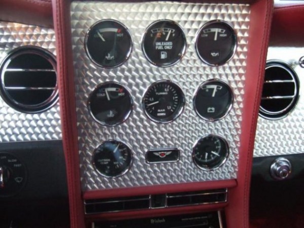 | |||
Richard Treacy Grand Master Username: richard_treacy Post Number: 2594 Registered: 4-2003 |
Again Lluis, You were writing that your boost solenoid valve was lazy. How did you revive it ? You may remember that 10V was not enough to make mine pick up. Today I decided to clean it out in case it was still weak with 10V, and I wanted it fully functional before my TB tests.. First I cleaned it with petrol, the decided to blow it out with compressed air. FORTUNATELY I put the compressed air on the bleed port completely by mistake before energising the solenoid. BANG. I say fortunately, because it blew the top off the device. Noting was damaged.I found all the internals with the help of a magnet, and was then able to polish the innards. I also cut 2mm off the return spring, about 15mm free length originally, to make it slightly more sensitive. Then the housing top simply snapped back on, and it works down to 8V now. So, my stumbled-over method to clean these things up without resorting to a new one (BTW a Saab Turbo part made in Sweden by SEM). Attach an air hose to the bleed port, put the solenoid in a plastic bag, apply 400kPa to the hose and BANG it opens up for a proper refurbishment without levering or damaging the all-plastic housing. Collect the bit from the bag and do the stuff. I may used this method on every Turbo Bentley equipped with the black plastic SEM valve I tinker with as the all seen to be malfunctioning. There is nothing to wear out or perish in the solenoid, so improving and polishing the existing one must be better than fitting a new one. RT. PS the relay mod is still a good one as it is kind to the ECU, as found on Jamesí Turbo R. This is not an exploded view of the boost solenoid rather a view on an exploded boost solenoid valve !!  | |||
LluÌs Gimeno-Fabra Prolific User Username: lluÌs Post Number: 209 Registered: 8-2007 |
Dear Richard, The car is back with a nice and quiet compressor... what a pleasure. I drove yesterday to Schiphol without boost control and the car is indeed a delight at part throttle acceleration, confirming that I want to modify the boost pressure signal to have better mid-throttle response and in the higher regime, hope that 0.7-0.8 bar is not too much. To answer you question: I cleaned the electric connections. I applied WD40 through the openings. I finally disassembled the unit, lost the spring, found it again and cleaned everything eliminating three rounds of spring. I noticed a patch of dirt which may be the source for the odd failures, but my relay always clicked on start up. All in all I think that the system is much much better now. About the potentiometer, this is how my valence area looks like in my car the sensor connections are buried under three layers of connectors. I noticed in TSD 6000 key to 7-2 (I cannot reproduce it from an Apple, IETIS does not support it and I still have not bought a windows lap-top) that the boost pressure sends a pressure signal to Mastercheck pin S throught the green-purple wire, I guess it's just a bifurcation of the signal send to the boost ECU... why would not we earth that signal with the potentiometer and avoid all the soldering in the engine bay area and the hassle of bringing the cable to the cabin? Best regards, LluÌs | |||
LluÌs Gimeno-Fabra Prolific User Username: lluÌs Post Number: 210 Registered: 8-2007 |
Here is the area...  | |||
Richard Treacy Grand Master Username: richard_treacy Post Number: 2597 Registered: 4-2003 |
Lluis, I understand your motivation concerning soldering etc, but I find a few connectors at the right place easiest to manage. I am happier to do nothing inside the cabin and do it all locally underbonnet by the RH wing near the Motronic stuff. I have wired my bespoke (and fully adjustable) TB kit using a new microswitch to save tapping into the TPS. So, I can activate TB Before kickdown if I wish. That will be nice: a rush of power without the commotion of kickdown and high revs The new circuits (I could call my PCB an ECU if I were adventurous) all work, and I have set the timers to match the Crewe kit for now. It became too cold and late as I only had two hours to work on it today, so the final commissioning will come maybe tomorrow night. Here are my takeoff point for the TPS/MAP, and my jury-rigged microswitch on the throttle near kickdown. Incidentally, with the APT/MAP signal opened, the original Boost ECU input floats high to over 4V indicating around 700mBar boost. This is a safe failure mode in case of a poor connection in service. Were it to float low, then the thing would boost to the dump valve limit until the knock sensors kick in. Opening the connection, as seen by the ones I fitted today below, the boost solenoid then kicks in and goes flat out at about 4Hz trying to open the wastegate. That is a good way to exercise a lazy boost solenoid !! RT. 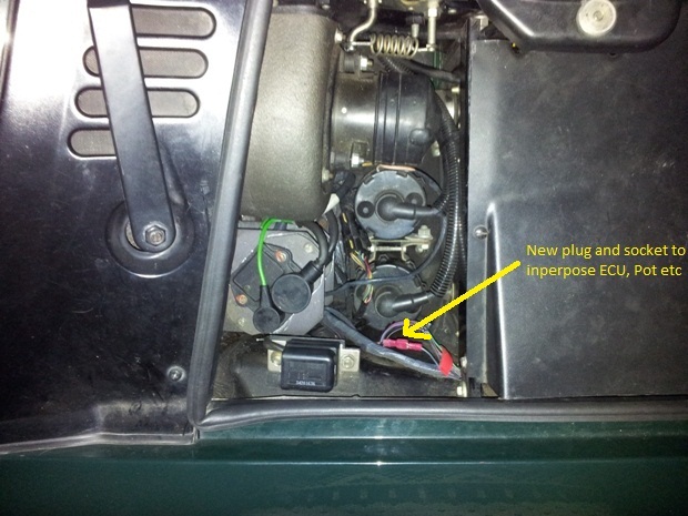  | |||
LluÌs Gimeno-Fabra Prolific User Username: lluÌs Post Number: 211 Registered: 8-2007 |
Hello again, It's nice to see the progress and I am looking forward to reports... I have found the connector to the MAP which is accessible, bit my question remains that Marstercheck has a nice active pin ready for boost control. By far I am illiterate in all things electric, but what happen when you earth that S/T pin through a potentiometer instead of having one in the engine bay that I cannot play with? Best regards, LluÌs | |||
LluÌs Gimeno-Fabra Prolific User Username: lluÌs Post Number: 212 Registered: 8-2007 |
OK now I see what you did, I guess you start a 3 sec timer with the microswitch that sends a sends a flat 12V signal to the BCS, would the knock sensors kick in the relay disconnects. Is this right? | |||
Richard Treacy Grand Master Username: richard_treacy Post Number: 2598 Registered: 4-2003 |
Hallo again Lluis, Mastercheck pin: if you shunt the signal with a potentiometer, you will probably ruin the APT. You need to put the potentiometer in sries as shown above: open the connection at the APT then fit the pot from the signal to the chassis. The output to the ECU is the pot wiper. The timer: not quite as you say as I can adjust it. When on high TB, a fixed dummy APT signal of 3V is OK Crewe-style, but I simply attenuate the existing 3.8V or so (at 600mBar boost) signal to 3.1V. 3.1V is what the boost ECU limits the signal to. If I am concerned at pushing it too far, I may reduce the attenuation. Likewise intermediate TB attenuates the signal such that 3.1V corresponds to 420mBar boost. In between are sliding values. The timer values are adjustable from 0-20 seconds, likewise the reset time 20-60 seconds. RT. | |||
LluÌs Gimeno-Fabra Prolific User Username: lluÌs Post Number: 213 Registered: 8-2007 |
Of course what an idiot, my idea was to earth the APT through a resistance, I had not realise it was a danger... I will connect the potentiometer in line now that I found the connection. 100KOhm potentiometer How much resistance have you put in the wire? And hell, how DOES IT DRIVE??? | |||
Richard Treacy Grand Master Username: richard_treacy Post Number: 2599 Registered: 4-2003 |
Hallo Lluis, Mine device is still on test so I cannot give fully accurate final figures. However, if you look at my last potentiometer diagramme, there is a 100k resistor between the bottom of the pot and the chassis, and the pot itself is 100k. That is perfect for tests, although the test results will indicate an optimum pair of valuesd for everyday driving. In that configuration, about the top 40K (40%) of the pot will be useful, providing an attenuation of 80%, as at that level of attenuation 600mB will be called for on full load. You may find that using more of the range is what you want to increase the mid-range boost, so I came up with the 100k values. With the pot on minimum, the signal will be attenuated a little less than 50% (the 4V float level of the ECU with its 300k impedance will raise the signal just above the 50% level). I expect that attenuating the signal to less than 70% or so will make no difference compared to 70%. The only possible question is what happens when you move it too far. That is, the MAP signal is attenuated too much and goes out of range, but I expect that the boost ECU will not care. Most likely for service I would probably recommend changing the fixed resistor to 150k and using a 50k pot to improve the resolution, but your tests and mine will reveal all. To achieve 600mBar boost with 150k fixed + 50k potentiometer, the pot should be set to 40k. That would mean that you could reasonably use 80% of the range of the pot, but again your tests with the 100k+100k will determine whether you need more range or less. RT. | |||
LluÌs Gimeno-Fabra Prolific User Username: lluÌs Post Number: 214 Registered: 8-2007 |
Hello again, This is the potentiometer installed: 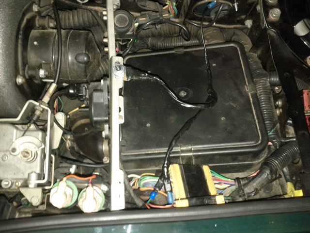 I installed it through one of the holes of the plastic cover, so that it is easily accessible by opening the bonnet, in case that it works as intended I will move it to the cabin. It's set up at 50% pot with a 100K resistance to earth. Let us see what happens, I will report. LluÌs | |||
LluÌs Gimeno-Fabra Prolific User Username: lluÌs Post Number: 215 Registered: 8-2007 |
Hi again, There are two more things that I wanted to report on. I found the spring in the solenoid to be completely rusted, probably cooperating with unreliable solenoid operation... I wonder why, could it be condensation? Finally driving with an open MAP, I found the gear changes to be terribly hard, so I think that there is something else going on than just boost control. Best regards, LluÌs | |||
Richard Treacy Grand Master Username: richard_treacy Post Number: 2600 Registered: 4-2003 |
Got it. That behaviour is quite correct. The APT drives the transmission system pressure, just like the vacuum modulator on a conventional transmission. See the file attached below. What you are experiencing is to be expected as disconnecting the APT upsets the transmission. However, I expect that it will be fine once my TB is fitted so I have not raised the issue beforehand. Depending how far you turn the potentiometer, you may feel the changes to soft on light throttle. On full throttle the changes will always be fine. For now, my ownh circuit only operates at full throttle, so the transmission will barely norice anything at all. With the MAP/APT open, the line float high to 4V as mentioned earlier so the transmission thinks that the boost is always full. That pushes the transmission pressure high and gives rise to firmer changes. Hence the rough changes. Once the pot is connected it should return to normal. In the worst case, if the grearchanges turn too slushy with the potentiometer in circuit, then the ATP-MAP signal to the transmission ECU may be rerouted. The connector is just near where you are working. In that case, simply disconnect the signal at the transmission loom (24 way connector, Green Purple wire) and reroute it to before the potentiometer (Green-Purple wire). RT. Shown are where the APT connects to the transmission circuits. You may download the complete transmission schematic here: http://rrtechnical.info/autotransmissions/3l80/3l80electrics.pdf And with markings: http://rrtechnical.info/autotransmissions/3l80/3l80electricsmarked.pdf 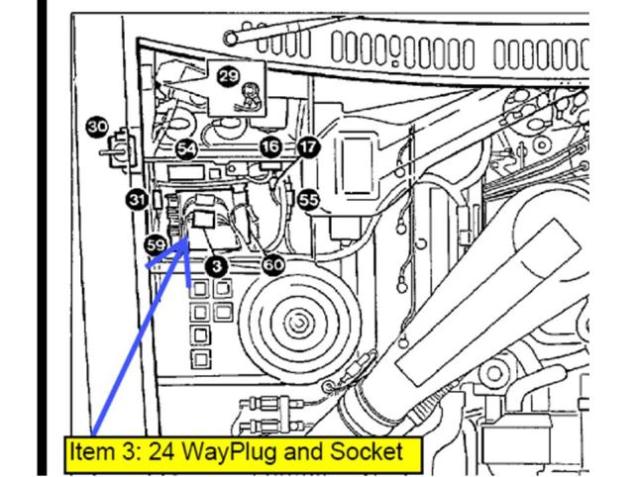 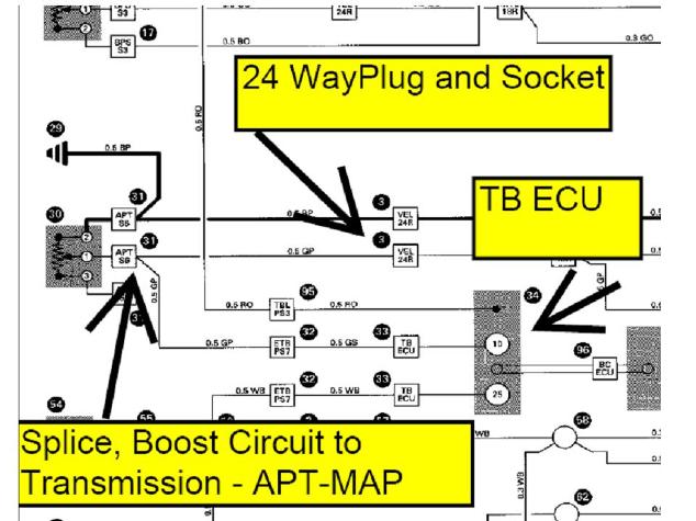 | |||
Richard Treacy Grand Master Username: richard_treacy Post Number: 2601 Registered: 4-2003 |
ps: with the ATP wire disconnected, as stated the signal goes to 4V causing harsh gearchanges. As that is a high signal, it may or may not exceed the fault detection limit in the transmission ECU, code 35. Did the CHECK TRANSMISSION warning come on ? If so, look for Code 35 in Mastercheck or with the blink code method (boost sensor high): 35 Boost sensor high effect: Maximum line pressure (Turbocharged cars only) For a fixed potentiometer application like yours, I would consider disconnecting the Green-Purple wire at the 24 way plug and connect the side going to the 24-way across to the Green-Purple wire before the potentiometer. That would ensure the correct transmission behaviour, but a road test beforehand will reveal all as I do not expect there to be very much effect really. RT. | |||
LluÌs Gimeno-Fabra Prolific User Username: lluÌs Post Number: 216 Registered: 8-2007 |
Hello, This is the first drive report: I drove the car in the the city for a few kilometres to get it to temperature and then went to an area of the highway which is rather quiet. The potentiometer is at 50%. Mid range response is certainly improved (from 2500 rpm) at part-throttle whilst there is what so ever no change at full boost, which is fine, means that my transient was working before, as i always thought and that the dump valve is doing its job now, which is safe -i had never complaint of ultimate performance-. Gearchanges are imperceptible again (thankfully) so no need to modify wiring. The most evident change in my car is the part-throttle transition from 3000rpm to 3800rpm, which is were you want to take over without going full blast, it's really much much much better. I also bought a pair of very nice connectors for Mastercheck pins to follow the boost pressure with my Volt-metre, which has a peak function so that I can draw graphs, I will report with the different settings, but I need some time and trials. Richard: No, there was no engine check or gearbox check message in the screen with the APT connector disconnected, the car was not nice to drive however. On the otehr had this is good news, as it means that would a solder let go I would notice almost immediately with gear change quality -once I had solder melt in my Jaguar during a "Stau" in Munich after a sub-1 hour drive from Nürnberg (193 Km/h average...). PS: What would be the modification needed to be able to follow knock detector operation with a led? PSbis: That the turbo is working harder is also clear, means that I will have to take even more care of oil changes and follow the engine temperature. PSbisbis: The oil temperature gauge will soon be a boost pressure gauge. PSbisbisbis: What I really like of what we did, is that it seems quiet safe and is easilly reversible, even during a trip would the potentiometer fail, as I arranged it so that the spades connectors for the original wiring simply matched. Since boost is not dramatically increased, I have little fuelling worries. Last but not least, when I am finally finished with my Jaguar (restoration of a family car which makes no financial sense but which I like) I think I will consider removal of the second cat in the Bentley -which is perfectly legal-. Tonight I am driving back home with the pot at 75% and will hopefully report. Best regards, LluÌs | |||
Richard Treacy Grand Master Username: richard_treacy Post Number: 2602 Registered: 4-2003 |
Lluis, I all sounds good. One point on the boost signal at Mastercheck: it will have to be the one for the Motronic as you are tricking the one for the boost system with the potentiometer. I do not know which Mastercheck brings out, but can be fairly certain that it is the one you want. Otherwise you would need to run a wire straight from the APT/MAP transducer before the potentiometer or straight from the Motronic's APT. On the LED, SAAB style, I am already looking into that. Also my oil temperature gauge is for nothing too. I have researched some 52mm boost gauges already. The trouble is that most boost gauges read up to at least 2 Bar, and we need one which reads up to 800mBar. I am ready to test my home made ECU gizmo on the roadf when I have a chance during the week. It all functions correctly in the garage. RT. | |||
LluÌs Gimeno-Fabra Prolific User Username: lluÌs Post Number: 217 Registered: 8-2007 |
Hello again, The drive back from work was even better than the way to work this morning... I had increased the potentiometer to 70% and it is quite perceptible that the boost kicks in earlier, about 2200 rpm, as for gear changes they are barely noticeable at low rpm, maybe just a bit more than usual, but really barely perceptible. Tomorrow I am going to work with the pot at 100%. The pot is now under the plastic relays cover in the configuration here, where the big o-ring is in the place where the screw used to be near the wiper arm:  It will stay there as I cannot find any convenient hole to pass cables cleanly into the cabin without dismantling half of the car. The behavior of the Turbo begins to be what I wanted, as the dump valve is keeping things in order at high boost I am not worried and I am getting boost a lower revs, the car does feel lighter and I wonder why it was not like this before from Bentley, it's really much nicer to drive under normal spirited conditions. It's with great interest that I will hear about anybody slightly raising the dump valve opening pressure, as this may be the next step in combination with second-cat removal. Best regards, LluÌs | |||
Richard Treacy Grand Master Username: richard_treacy Post Number: 2603 Registered: 4-2003 |
Great news Luis, It's so rewarding when such a simple tweak makes such a difference !! What size pot did you end up using, and did you fit a fixed resistor too ? 100k + 100k ? RT. ps: Phase I: my TB circuit works very well, and I may tweak it to have the same solution as yours when TB is not called for. Goes like stink ! | |||
LluÌs Gimeno-Fabra Prolific User Username: lluÌs Post Number: 218 Registered: 8-2007 |
Hi again, It's the 100K pot+100k fixed resistance that I am using from your schema, my wife soldered it for me... (I work with the noblest material of all only: paper) I drove today at 100% pot and indeed the boost has further moved to lower rpm. I see that the hot turbine of our cars is clearly under-dimensioned and that the cold turbine is huge, this is purposefully done to have the turbo spin at low rpm, our engines generate plenty of moles of hot gas, so it makes sense that we can fine-tune so well the low-rpm response. With the recirculation system operating properly no over-boosting either, which is safe for the pistons and gaskets, nice. But the bad news I believe is that it is critical to keep that little hot turbine under control as lubrication is limited and we don¥t want it to over rev: we are modifying the wastegate reaction with the APT signal but by limiting boost only with the recirculation valve we could have the turbo over spinning, turning air at 0.67 bar. In other words: Knock detection protects the engine, but with our toy we could over-spin the turbo couldn't we? Let us see: My APT gives 2.33V with the pot at 0% and 2.10V with the pot at 100%, so that would mean, in case the solenoid response is linear more or less an increase in boost of 10% for each point of the curve, that would be 0.47 Bar (1.340Bar+10%) in usual operation. I need to check with a real gauge. On transient that would be theoretically 760mBar, but in practice I have seen 670mBar without any modification, and that means about 840mBar with the pot at 100% (in case that solenoid signal was the limiting factor). I think it's rather safe, but what is your opinion? Are you going to try 200KOhm pot? My problem with bringing boost into ever-lower regimes is that I do not want the turbo to blow at below 2500 rpm at low (1/3) throttle openings, as this is comfortable cruising and I don't need it and I do not want to cook it in a few thousand miles either. Opinions are really very welcome. Best regards, LluÌs | |||
LluÌs Gimeno-Fabra Prolific User Username: lluÌs Post Number: 219 Registered: 8-2007 |
And by the way: I know it sounds stupid but: Are you really sure that the APT sends a signal to the Motronic ECU, I cannot find it anywhere, there is only a split, but this is one going to Mastercheck, one for the Boost control ECU. Surprising as it is, I think that Motronic does not have contact with the APT. | |||
LluÌs Gimeno-Fabra Prolific User Username: lluÌs Post Number: 220 Registered: 8-2007 |
Clear I now see it in the diagramm. pins R, S, T correspond to ignition, boost and barometric. | |||
Richard Treacy Grand Master Username: richard_treacy Post Number: 2604 Registered: 4-2003 |
Dear Lluis, I have absolutely no concerns over the Garrett TO4B turbocharger. This is a truck unit designed to work three times harder for two million kilometres. Trucks run full boost for hours on end, while we scratch the capability for a few seconds at a time. Even flat out on the Autobahn, the Turbo is napping. 1 Bar is common for turbocharged production motor cars, and we are at only just above half that level. Let alone the 2 Bar cars out there. What does concern me is WHY Crewe dropped the boost for Cat cars. The turbocharger on my non-cat Turbo R (340,000km and no turbocharger attention whatsoever) is always on-song and runs at 430mBar continuous if called upon, whereas unmodified the Conti R cat engine is not using the turbocharger much at all and only tolerates 420mBar in transient. It is the catalytic converter itself Crewe was worried about damaging with continuous high boost (not-so high really) ? RT. | |||
Richard Treacy Grand Master Username: richard_treacy Post Number: 2605 Registered: 4-2003 |
By the weay here is my transient boost ECU in position and working fine. Note the boost control repeater relay (black) adjacent to it. I could only try it out in peak hour traffic, but did hit 550mBar once on the test gauge. Iíll check it out properly when on the highway. RT. 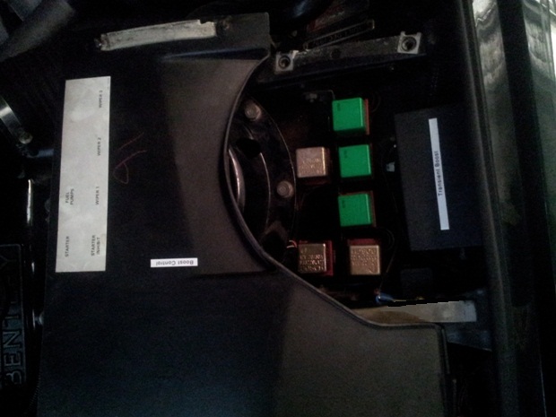 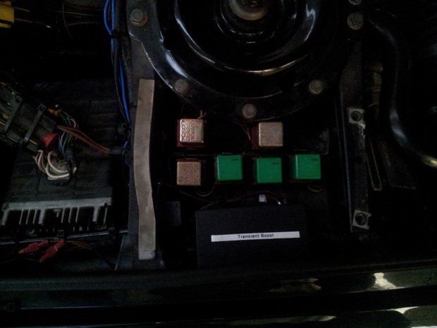 Not much to see really. 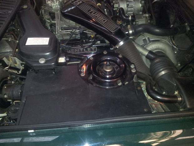 | |||
LluÌs Gimeno-Fabra Prolific User Username: lluÌs Post Number: 221 Registered: 8-2007 |
Hi again, Your worries are mine... that is why going beyond a given band is madness without having more data, but nevertheless I have the feeling that the only reasons why boost was reduced were emissions with the "primitive" motronic system. In as much as I know the Continental S later Continental T have identical exhaust systems and turbos and both have higher boost pressures, all due to higher intercooling capacity, not exhaust restictions. I guess that as long as we are only moving the boost curves around the risk of melting the cat is minimum, the fact that there is a separate fuelling calculator should compensate moderate increases in boost, reading the AFR at boost levels of 0.8Bar would be a must. By the way Richard: can you confirm or the opposite that the boost controller in our cars is 100% Saab? in that case I would have a very interesting information concerning their adjustability (not programming). Best regards, LluÌs | |||
Richard Treacy Grand Master Username: richard_treacy Post Number: 2606 Registered: 4-2003 |
What I can confirm re Saab is that the boost control solenoid is a Saab Part Number 7517477. The rest looks the same too !! Lots of bits are clearly pure Saab, the pioneers of production turbo cars designed to go shopping and do school runs (as we do in our Contis of course). Garrett or otherwise turbocharger hardware is of little consequence, but our Turbos have Saab wherever you look ! RT. | |||
LluÌs Gimeno-Fabra Prolific User Username: lluÌs Post Number: 222 Registered: 8-2007 |
Dear Richard, It's confirmed. I spoke to our Turbo man here who worked 12 years in Renault in the engine department, doing cat and turbo set up (fortunately for him we rescued him and now he does only paper...) The catalyst version of a model (in the days when there were non-catalyst versions) had to pass a more stringent pollution cycle control for legalization (not only less than 0.5CO, but a dynamic cycle measuring NO, CO, CH, CO2), and therefore the boost control unit was adjusted to make the full test without spinning the turbo which would increase pollution in the very specific cycle. Bentley was not alone, this was common practice. This was not only for the stationary legalization, but also for the dynamic tests... under acceleration (he has talking from memory but in those days it was something like 15-30Km/h, then 30-50 and so on with ramp up and steady cycles). In case our boost controllers are Saab-style, normal in the 90's they have three internal adjustable potentiometers, one for knock sensitivity (do not touch), one for pressure attenuation and one for pulse length to solenoid see the image below and explanation here:http://www.sacsaabs.org/speed2.htm In that case what we just did was to externalise the pot. Would you feel bad for pollution, he re-assured me, the pollution legal cycles have nothing to do with reality. And on Friday I am getting a second cat substitution pipe ordered :-) to fit exactly the original pipe. Best regards, LluÌs  | |||
Stefan Morley Grand Master Username: myupctoys Post Number: 358 Registered: 7-2009 |
Hi Guys, Just looked through the thread. Luis, that is a very neat engine bay. Mind boggles at the volume of air a 6.75 L engine would consume under 2 Bar. Cars that run this sort of boost reliably have a lot more effort put in than just cranking up the pressure. Lot of things come into play, not least higher flow injectors. Drove a Nissan Silvia (3L) that had a relaible 33PSI. Not much of the origonal engine management or fuel system left. Wen't like stink but compared with the B performace way too peaky for my liking. But the thought and engineering that went into it was impressive. Reading the thread I'm looking forward to resolving the remaining issues with my car. Keep it up. Cheers Stefan | |||
Richard Treacy Grand Master Username: richard_treacy Post Number: 2607 Registered: 4-2003 |
Lluis, Pin 19 on the boost ECU goes to ground when the engine knocks. A knock LED would simply be wired from Pin 19 to the +12v ignition circuit. Unfortunately, unless by chance it is wired to Mastercheck, the pin is not used on our cars, so you would need to run a cable from the ECU in the front wing all the way to the dashboard. Thatís quite a job in the wiring, but simple in concept. RT. ps better start a new thread soon !! | |||
LluÌs Gimeno-Fabra Prolific User Username: lluÌs Post Number: 223 Registered: 8-2007 |
Hi all, Last report from my side before any further modifications: I have left the pot at 100K, it's really flying and I start to see that wheel spin is the next step, so for the time being 100K will do and possibly when I have time I will install a cabin mounted pot with 200K. Richard: Yes, let us start a new specific threat on boost control. I propose to treat inter alia the eventual modification of the boost controller settings in case that it is feasible. I can open up my boost controller, but I am visiting a Trappist monastery next week end and I guess that they don't have the tools. Other issues could be the fine tuning of the the settings and in case somebody has the time, information on a rolling road session and eventual problems. I saw that neither of you did comment on the information above, but have you seen the inners of the boost controller? Stefan speaks about the remaining issues with his car: what are they? maybe Richard's relay or a dirty solenoid could be the missing link in your boost system? Richard. my solenoid is kicking bloody well now, would you still advise of fitting the relay? I know it's a stupid question but, taking into account that we replace a solenoid direct activation, I guess the relay does not need any diode protection? Last but not least, Mr. Blasco, the guy I had ask concerning boost pressure is categoric: there is hardly any catalyst risk for increased boost, what suffers is legal-cycle emissions but not real-life... he is a real expert in design of boost systems -he does this for a living from a very academic perspective-. Best regards, LluÌs | |||
Omar M. Shams Prolific User Username: omar Post Number: 265 Registered: 4-2009 |
Dear Richard, WOW!!!!! OMG!!!! The car felt like a bullet with those pipes disconnected from the boost control solenoid. I love the car now!!! What next? My boost solenoid appears to be a sealed aluminium thing that I will not be able to dismantle. I understand that I will need to relocate it - that is easy. But what do I replace it with? I am amazed that you were able to diagnose my car's problem in Dubai whilst you are at the other end of the planet!!! Thanks again Omar | |||
LluÌs Gimeno-Fabra Prolific User Username: lluÌs Post Number: 234 Registered: 8-2007 |
Hoi Omar, Just get a Saab solenoid, clean it well like we did and re-locate it with a nice ceramic relay to activate it. I drove yesterday my car monitoring the boost pressure (+ the potentiometer-modification), 400MBar from 3000rpm without transient, it's great. Anything beyond 600MBar, with the pipes disconnected and wheel spin is really near, which is too much for me, as I also drive the car in winter. Best regards, LluÌs | |||
Richard Treacy Grand Master Username: richard_treacy Post Number: 2628 Registered: 4-2003 |
Omar, I would suggest that you test your boost solenoid valve first. Those early metal ones seem to be more reliable on a Bentley than the later SEM-Saab plastic ones, but it sure sounds that yours is central to lack of boost. As pointed out earlier, the Saab people have no difficulties with their solenoids located in a cool place. My theory is that, due to its silly location and the wide heat cycles on a Bentley, the plastic valve seat inside the solenoid valve becomes soft with age and becomes slightly adhesive with heat. Disconnect the hoses. Make sure that air can flow between the two pneumatic connections to the solenoid adaptor ñ one goes to the turbine and the other to the wastegate. Blocking one solenoid adaptor and blowing down the other, no air should escape from the bleed port. If it does, then the system can overboost (not likely as we are looking for more boost). Next turn on the ignition and check for the solenoid clicking as it energises with 12V: the air should vent through the bleed duct. If so, the solenoid may be functioning but sticky and could respond to cleaning out with petrol. You may even do a road test with the solenoid connected pneumatically and energised all the time to give full boost. If the solenoid is not clicking or opening, give it a tap with a screwdriver handle. If nothing happens, use a voltmeter to see if 12V appears at its terminal when you turn on the ignition. Operating the brakes should turn the solenoid off, as should activating the Cruise Control. If there is no voltage on the solenoid, then you will need to look deeper into the wiring to the boost control module in the front left wing. In any case, from our recent observations I do agree with Lluis that a relocated solenoid and a solid state relay are the way to go. If your solenoid needs replacing, you may choose between the original metal type on your car or a plastic SEM-Saab unit. The Saab ones are available secondhand at a very reasonable price. A ceramic SS relay will need a transistor driver, simple if you are handy with Verroboard and a soldering iron. RT. By the way, although probably quite safe, I donít like running the motor with those hoses disconnected as there is no knock protection. By contrast, Lluisí potentiometer doesnít bypass the knock protection. | |||
Richard Treacy Grand Master Username: richard_treacy Post Number: 2629 Registered: 4-2003 |
Omar, I am assuming that your solenoid valve looks like this:  | |||
Omar M. Shams Prolific User Username: omar Post Number: 266 Registered: 4-2009 |
Dear Richard and Lluis, Thanks for all your support. Its is way too hot for me to tinker with cars now - so i will put things on hold till the ambients drop below 52 degrees C. The Bentley really struggles to keep me cool inside the cabin in these ambients. In fact they all struggle to keep the occupants cool - not just mine. I will hold off doing work on it till September. Meanwhile - here is a question: if the ambient temperature never drops below 15 Degrees C is there any risk of the engine knocking at all? My question is aimed at the "do nothing" option: ie just leave the tubes open to the elements. The silver solenoid is indeed the type I have on my car. Many years ago, I took it apart and found that it has a conical seat that never actually sealed properly. I may tear into it again. I am concerned that there may not be 12v at the two terminals. Best for me to wait till after September to have a good hard look at the car. Thanks for all your help guys. Omar | |||
James Feller Prolific User Username: james_feller Post Number: 204 Registered: 5-2008 |
Omar, yes its highly addicative fun when these old Bentley turbos are running back up at their potential. Taking those two tubes off the boost solenoid and expirencing full and unbridled 600mbrs its amazing !! RT and I did that to my 89 Turbo RL too prior to the work we did on resurrecting the system electormechanically. Its wasnt a concern as I only use 98 Octane fuel. We have now relocated my boost solenoid and its giving wonderful relaible and solid performace now, we are working on transient boost to give my back the full 600mbrs fully protected by the knock sensors. My question for you Omar is you should have a Black boost solenoid on a 91 Turbo RL yes? the metal types were on earlier cars I assumed... Goldie as we are calling her, is the Transient Boost soleniod. Is this the case for you Omar on your car? does yours have a Trasient boost system Omar? On the heat in Dubai 52'.....jesus...I think most cars struggle to keep passengers cool in those temps. Old English cars in those temps would scare the hell out of me....I think you are very wise Omar in keeping the older 'Pommie carragies' parked up till it cools down for them. BTW, on my way from Sydney to Mudgee last night is was between -1 and -4 most of the way....intercoolers like this better!!! ( yes it is winter in Australia at present) As for engine knocking Omar, the ambient temp has little if nothing to do with it, its poor combustion or detonation that is 'knocking' and its poor fuel quality and low RON that causes Knocking I believe. If left unchecked it can completely destory the engine very quickly.... Good luck with it Omar, as you can see now there is nothing wrong at all with the performance of these great old brutes of cars huh!!! What RT has helped me to do on mine with is simply astounding and I just cannot help myself...I hoon around in a 2.5 tonne Blue Bentley like its a go cart!!! its hilarous and addictive fun!!! | |||
Richard Treacy Grand Master Username: richard_treacy Post Number: 2635 Registered: 4-2003 |
Actually, James, your car has been altered presumably when the transient boost was fitted. That was likely partly to suit the later type of mounting arrangement which came with the kit. The UE71363 earlier type of solenoid valve continued through to the end of the 1990 Model Year. The very first 1991MY Turbo car car (Turbo R chassis 33148) is the last listed in the spares schedule as a lucky one without the black plastic type. Sure it is likely that by now there has been some swapping going on though. RT. | |||
LluÌs Gimeno-Fabra Prolific User Username: lluÌs Post Number: 238 Registered: 8-2007 |
By the way Omar, I would very respectfully disagree with James, Knock is very much temperature dependent, as it concerns spontaneous pre-ignition of the mixture, not only temperature indeed, but also inlet temperature affect it and we are not talking a couple of degrees here... and it's an air-to-air intercooler that you have. I would think that the difference between 25∞ and 30∞ is not much, but at 56∞C I would really advice NOT to get rid of knock sensor protection. In case you don't have right now the time to make the modifications above, I would just order any three-way boost control solenoid (Saab) and wire it as original until you can do the full modification. Maybe I am paranoid, but a) you are not running 0.6 Bar with the hoses disconnected, but higher (I check on my car and saw up to 0.8 Bar on full throttle for a couple of seconds when simply relying on the dump-valve) and b) 56∞C is something beyond imagination at least in Europe. Best regards, LluÌs | |||
Omar M. Shams Prolific User Username: omar Post Number: 268 Registered: 4-2009 |
Dear James, Lluis and Richard, Many thanks for your posts. My car is a Japanese spec 91 car that has no Transient boost but does have a silvery aluminium boost control solenoid. My point about ambient conditions is to do with air density. The high ambient conditions result in a lot less oxygen being available per unit volume. The turbo can kick out as much air as it likes, there just isnt going to be that much oxygen in the air to weaken the mixture enough to get it to knock at 50+ degrees C. The air fuel ratio will err on the richer side as volumetric efficiency decreases. This was my thought process when I asked the question originally. | |||
Omar M. Shams Prolific User Username: omar Post Number: 286 Registered: 4-2009 |
Dear Richard, Now that the weather is nice - I got the Bentley out to do the checks you suggested. The solenoid clicks when the ignition is switched on and also clicks when the brake pedal is applied. When its connected to the vacuum pipes, I get boost pressure of 3psi. When I disconnect the pipes, the boost pressure goes up to 6 psi. I do not register any form of knocking when I am up at 6 psi boost - In fact I never register any knocking under any conditions. I always use 98RON fuel in this particular car. What can I do to get the right boost pressure? Incidentally whenever I get the 6 psi pressure its often associated with a time lag before it gets to 6 psi. Thanks Omar | |||
Richard Treacy Grand Master Username: richard_treacy Post Number: 2686 Registered: 4-2003 |
Hi Omar, Almost certainly the boost ECU is functional, but there is that chronic issue with the knock sensor plugs continuity. We have had quite some success in that regard by cleaning the contacts at the KS plugs, and best with brand new connectors. Replacing the connectors is a bit of a beast of a job but very rewarding. Although the plug terminations are crimped, it is highly advisable to solder them on for improved security. To explain, the ECU must detect noise, ie 2 beats per revolution for each 4-cylinder bank, from the KS before it allows the boost to rise above base. It allows the normal boost until the KS sends 2kHz to 5 kHz signals to the ECU indicating detonation / knock. If the connectors are bad, as they usually are by now, the ECU cannot detect the low-frequency noise so assumes faulty sensors and restricts boost. If you need new connectors do let me know. I am in Switzerland until November 6 so can send some plugs to you after then. The boost solenoids sometimes suffer when hot even though they are fine cold. Do check the solenoids functional clicks after a hot run/ RT. | |||
Omar M. Shams Prolific User Username: omar Post Number: 287 Registered: 4-2009 |
Many thanks For the swift response Richard. Best regards Omar | |||
Stefan Morley Grand Master Username: myupctoys Post Number: 359 Registered: 7-2009 |
Richard, Absolute Gold. Comment makes so much sense. Didn't dawn on me the knock sensor inputs needed to see a degree of "knock" to allow the system to function normally. Fail safe really. Accounts for a test I ran ages ago trying to short those inputs and why that made no difference. Still have a fuel pressure issue but that comment sits very comfortably to resolve the remaining issue. Many thanks Stefan | |||
LluÌs Gimeno-Fabra Prolific User Username: lluÌs Post Number: 276 Registered: 8-2007 |
Hi all, For me it will be new Bosch sensors when the flue I have is gone. I will relocate them elsewhere in the block as distance from piston is not critical I have been told. Richard and all others who followed the discussion: I am running now on 2Volts base APT signal with a 25 K pot and a 50K resistor: my dear, do try it just for the fun of it... really. 0.7 bar is achieved from 2200 rpm at half gas, then the recirculation valve kicks in (you can hear the wooooosh) and the frequency to the solenoid stabilises (I have an oscilloscope with pulse measure). Wonderful. I promise to write a full report some time soon. LluÌs | |||
Omar M. Shams Prolific User Username: omar Post Number: 289 Registered: 4-2009 |
Dear Richard, How far up should I chop the wire and put a new wire/connector assembly? Thanks Omar | |||
Richard Treacy Grand Master Username: richard_treacy Post Number: 2687 Registered: 4-2003 |
Omar, Just cut the wires right at the plug. There is ample spare length to sacrifice 1cm for the new plug. The plug is a standard automotive type by Bosch and the rest. The replacements I prefer have a quick release clip. The originals are such that the retaining clip must be removed with an instrument screwdriver to release the plug from the knock sensor and are fiddly. The replacements only need to be squeezed by hand to release quickly and safely. RT. | |||
Omar M. Shams Prolific User Username: omar Post Number: 290 Registered: 4-2009 |
Dear Richard, I looked under the car and could only find one knock sensor. Should there be a second one? Also the connector for that one sensor was dismal. It broke up in my hands and had been cable-tied together. The wires either end of the male and female connectors are all over the shop from a colour coding perspective.At the sensor end there are two wires and a bare sheath. The sheath makes one of the three connections. I need to cut the connector and start again. We have a Radio Spares shop here in Dubai amongst others. What would be the best connector to put? Thanks Omar | |||
Richard Treacy Grand Master Username: richard_treacy Post Number: 2688 Registered: 4-2003 |
Omar, You disintegrating plug is typical. There are two knock sensors on fuel-injected cars. Carburettor Turbos, ie before 1987, have just one, a crude tuned device sitting on the inlet manifold, a system which only retards the ignition if knocking occurs and only if you are lucky. They are not failsafe at all. Those early cars need care as if the KS is faultry the motors can blow apart if low RON fuel is used. The injected cars are, by contrast, annoyingly failsafe in this regard. Both your sensors are located half way along the cylinder block below the exhaust manifolds, one at the centre of A bank and one at the centre of B bank. The one on A bank is stupidly close to the downpipe from the turbocharger and is exposed to far too much heat. Once the plug has been undone you can remove the knock sensor from below in a few seconds using a standard 6-point spark plug spanner or a long-reach socket. That way, if your plug is completely ruined, you can take the KS to an electrical garage to find a suitable pair of plugs. Furthermore, the KS will need a very thorough chemical clean if you are to reuse it, and that can only be done with the KS removed from the motor. Radio Shack and the like are unlikely to stock the plug you need, but it is so widely used on motor cars of all brands that you should have no problem at an autoelectrician. RT. | |||
Omar M. Shams Prolific User Username: omar Post Number: 292 Registered: 4-2009 |
Dear Richard, I am confused. I could only find one knock sensor and it is located near the engine mounting on the gearbox. here is a photo of it. case.  | |||
Richard Treacy Grand Master Username: richard_treacy Post Number: 2691 Registered: 4-2003 |
Omar, That is not the knock sensor. You are looking at the timing sensor on the flywheel and torque converter lower cover. You need to look at UE70135 as shown below. RT.  | |||
Paul Yorke Grand Master Username: paul_yorke Post Number: 878 Registered: 6-2006 |
Omar. That's the CPS, wrong part I'm afraid. If only they were so accessible! Look in front of the starter motor.  | |||
Paul Yorke Grand Master Username: paul_yorke Post Number: 879 Registered: 6-2006 |
 | |||
Richard Treacy Grand Master Username: richard_treacy Post Number: 2692 Registered: 4-2003 |
Here is a typical knock sensor as removed. Notice the corrosion on the electrical terminals.   New Plug  | |||
Richard Treacy Grand Master Username: richard_treacy Post Number: 2693 Registered: 4-2003 |
Now, just to throw the cat amongst the pigeons I have, under evaluation on my Conti R with perfect results so far, an upgrade kit to fit modern knock sensors to these cars. The original Lamerholm devices are long out of production, even though Crewe fitted them to Arnages and later cars, so I have developed a kit which gives the exact mechanical and electrical performance criteria required whilst eliminating the silly issues with the original KSs. I have pictured the same B-Bank location that Paul has posted for comparison purposes. Note that the electrical plug, chosen to be a plug-in identical match for the Lamerholm type, is not connected in this picture, nor is the new heat shield developed to suit this KS to the Crewe V8. Those accessories improve matters even more. All KSs delivered by Crewe are now old stock but these superior new ones will be around forever. Note that the physical layout avoids the heat from downpipes and manifolds far better. On the A-Bank the improvement is far more striking. RT.  | |||
LluÌs Gimeno-Fabra Prolific User Username: lluÌs Post Number: 277 Registered: 8-2007 |
Hi Richard, Please correct me in case I am wrong. But as long as they are in direct mechanical contact with the block, you can relocate the sensors without the need to produce an adapter. Best regards, LluÌs | |||
Richard Treacy Grand Master Username: richard_treacy Post Number: 2694 Registered: 4-2003 |
Hallo LluÌs, What you point out is correct. However, I would be reluctant to move the sensors far from their present locations. Where they are now they are nicely central on each bank and towards the top of the bank where combustion takes place, and that is fairly optimal. Also, the block has machined surfaces for each sensor, thereby providing an excellent mechanical interface for each. The adaptor is a simple device which just screws in and may be removed just as easily. I donít see any available M8 or 5/16î UNF bolts or threads anywhere suitable for mounting knock sensors, so the M12 to M8 adaptors I have made to use the existing sensor threads in the block must be a safe and easy option. They also do not need any rewiring the way I have fitted them, and adding simple heatshields secured by the same fasteners as the sensors has to be a good thing. If you do find better locations, please let us know. RT. | |||
James Feller Prolific User Username: james_feller Post Number: 239 Registered: 5-2008 |
I can think of one RT but I suspect the moderators would cut my post out for profanity. As you and I both know, the KS locale is such an absolute mongrel to get at near the cat.... Was thinking rear if you get my drift....enjoy swiss! btw saw the doppelganger of your Conti R yesterday. Im gonna stop him soon and ask him is hes happy with the performance....and also steal his wheels J | |||
LluÌs Gimeno-Fabra Prolific User Username: lluÌs Post Number: 281 Registered: 8-2007 |
Hi, No need for moderators... I managed to disassemble the sensors from the block. Not as bad as I thought, but my car is LHD, which may help. No, there is no other suitable position for the Bosch units that I bought, at least on the LH bank, on the RH there is a bracket that I could use with a 6mm bolt, not 8 but close enough. Any way, tomorrow it's off to try to buy a suitable bolt to make an adapter for the original positions, which as James and Richard say are ideal. To make things more amusing I just ordered a 180HP Vtect engine for my classic Mini. It will be a fun winter with the Jag disassembled for restoration, the mini in pieces and a customised Continental blowing at a max boost from about 2000 rpm... Fortunately a friend lent me an Audi A4... LluÌs | |||
James Feller Prolific User Username: james_feller Post Number: 256 Registered: 5-2008 |
picking this thread up again, Lluis you are quite correct, knock has everything to to do with preformance in so much as heated air is much harder to compress and the warmer the ambient air the harder the compressors has to work....so I was factually incorrect in my post above as you pointed out. My 89 Turbo RL is now delievering 430mbars or around 6 psi on full load, reliably and everytime I want it and the rpm range is 3500-4000rpm full load. This is seen on my pressure gauge and im delighted that the Ole girl is thundering along most rapidly all the time. My issue is Transient Boost!!! if you remeber my car has TB fitted and thus it should give me an extra ooophm up to 9psi of 600mbars for 3-4 secons and then ramp down to 5-6psi as long as I keep my foot planted but not FULL throttle kickdown! its important to remeber that the knock sensors will back the boost off a little on kickdown, try holding the fun pedal slightly off kickdown but full throttle and see the difference. But I digress, the point is while me knock sensors are now working RT and I are fairly convinced that its indeed the excessive heat that makes the ones on my car very sensitive and restrict TB when the car is hot and indeed the temps outside are warm. The TB ECU works and behaves correctly, its our belief that my knock sensors get far too hot and thus wont allow TB dynamically when the car is hot. Stattically we have tested the system and it works perfectly.....so the up shot we will try some newer knock sensors and a better heatsheilding arrangement and see if at last my car will give 9psi and 600 mlbars fully protected. J | |||
Richard Treacy Grand Master Username: richard_treacy Post Number: 2817 Registered: 4-2003 |
So. Maybe 650HP at 11psi is the limit with the Garrett T04 on the standard 8:1 compression ratio. Next is to drop the compression to 5:1 and go for 22psi with twin IHI Turbos. Can we crack 1,100HP James ? RT.  | |||
James Feller Grand Master Username: james_feller Post Number: 304 Registered: 5-2008 |
Staggering pressures the 6.75 blown will give huh Richard....  if anyone can its u RT.....hope i dont hear the mighty bang all the way over here in blighty.... J | |||
Graham Burn New User Username: graham Post Number: 2 Registered: 6-2013 |
Hi Guys just read through this amazing thread and, like Omar, I think my boost solenoid is my problem too on my 87 Turbo R. When I switch on the ignition it seems sluggish to pull in, certainly doesn't snap on, so think it needs a clean at least. Mine is the same as that fitted to Omars car, how is the easiest way to get it off? the rigid pipes are just that very rigid and then the bracket seems very inaccessable any tips on that please. My boost is very inconsistent, sometimes it works sometimes it doesn't, not really ideal!! I'm going to check the supply voltage today and see what I get. Thanks Graham | |||
Richard Treacy Grand Master Username: richard_treacy Post Number: 2845 Registered: 4-2003 |
Those hoses are only rigid because they need replacing ! Generic black air/vacuum hose from any automotive parts shop will do. My '87 Turbo R has the same solenoid as yours. Removing it is no drama - just release the strap around its girth. It should click quickly and surely, unlike at least 9/10 that I have seen. I have replaced the hoses on my Turbo R and Conti R of course. RT. | |||
Graham Burn New User Username: graham Post Number: 4 Registered: 6-2013 |
Hi Richard, thanks for that, it wasn't so much the hoses I meant but the rigid pipes to which they are attached, I assume I can release the hoses and slide them down the rigid lines to give room to get the valve out then is it the 2 screws inboard and below to release the valve? Thanks Graham | |||
Richard Treacy Grand Master Username: richard_treacy Post Number: 2849 Registered: 4-2003 |
Indeed, Graham, it is as easy as that. Disconnecting the hoses is as quick as turning a door handle. Take the opportunity to replace the hoses. Best of all is to relocate the solenoid to a cooler place and to fit a solid state driver relay to relax the boost control ECU. RT. | |||
James Feller Grand Master Username: james_feller Post Number: 307 Registered: 5-2008 |
trust me Graham, the small but very worthwhile 'clean up' modifications will make the world of difference. AS Richard states, make sure you hear a good solid click from the solenoid each time you put your foot on the brake with ignition on. Make sure the kick down relay is functioning correctly by pushing the 'fun pedal' fully to the floor and you can hear it clicking and last but by NO MEANS LEAST make sure your knock sensors are working correctly!!! Its best to have a second person to help with these checks btw. If your KS are gummed up and corroded like 99% of older Turbos are these days you will only ever be thundering along with base boost (2psi instead of the 6psi you should have) in effect a 'quick' Mulsanne S at best....RT and I spent many many many weeks of trial and error figuring all this out. Moving the solenoid to a cooler environment is ideal and we both have done this modification after sorting out the sticky solenoids, non functioning relays and gummed up knock sensors first. RT, is the guru on this and trust me, when its 'brought back up to scratch' you will never loose your smile when thundering up the M1/M25 in a sorted Turbo R.... | |||
Graham Burn New User Username: graham Post Number: 6 Registered: 6-2013 |
Hi James, thanks for the encouragement and pointers, at the moment I sometimes get a decent boost then other times when I floor the loud pedal nothing too exciting happens, so I'm guessing my biggest issue is a sluggish boost solenoid, but once I get that freed up I'll go through the rest of the system and finally look at the modifications. Thanks again Graham | |||
Robin Hall New User Username: bombguy54 Post Number: 6 Registered: 6-2013 |
Turbo R 27723 I don't seem to be able to locate anything specific to my issue through the site search engine so I'll post here as it is somewhat related. Per the observations of others, it appears I, too, have a serious no/low-power issue. I've gone through the troubleshooting per the manual. Got to the Mityvac pressure test of the wastegate and I can't get any pressure to build which (I think) tells me that the wastegate diaphragm is damaged. My question is about gaining access to the wastegate. Any tricks, recommendations or pointers?} | |||
Omar M. Shams Grand Master Username: omar Post Number: 535 Registered: 4-2009 |
Dear Robin, perhaps you need to look at this thread instead: http://au.rrforums.net/cgi-bin/forum/show.pl?17002/12300 | |||
michael vass Frequent User Username: mikebentleyturbo2 Post Number: 96 Registered: 7-2015 |
Hi All Fascinating thread! I have a '89 turbo R kch27650 ,motronic ,(don't know which version sorry),(I have the 2 large round military style connectors by the right strut) Hope I have got this right step 1) connect voltmeter between were? to test/read boost pressure? step 2 if not getting 3.3V? on full throttle? or 2500rpm? I start checking a) knock senors b)boost solenoid c)do modifications anyway? Sorry if I'm being thick. Cheers Mike | |||
Robin Hall New User Username: bombguy54 Post Number: 7 Registered: 6-2013 |
Turbo R 27723 Per the posts of 7/12 involving the use of the Hella Solid State Relay. I have the relay but with regard to the components to get it to do what it is supposed to do: What are the "correct" resistors/transformers to use? I go to Mouser and their online catalog is massive with resistors/transistors of different capability/capacity. I don't know which ones to pick with acceptable wattage capability...or does it matter?} | |||
David Towers Experienced User Username: xtriple Post Number: 30 Registered: 6-2010 |
Sorry to drag this slightly off topic but.... My Brooklands 'R' is a low pressure turbo. I assume this means that it boosts to a lower amount than a full fat Turbo? However, when I compare part numbers for my car (66221) and a Turbo R (66222) the turbo units themselves are the same unit. I wonder if it is possible to up the boost on my car to the heady heights of the full fat cars? | |||
Richard Treacy Grand Master Username: richard_treacy Post Number: 3263 Registered: 4-2003 |
Surem you could push the boost safely to a somewhat higher figure. However, the Turbo RT you refer to (66222) diffwers from your rare shortwheel base Brooklands nainy ib that yours has no intercooler at all. The first injected Turbo Rs have no intercooler, but the an air-to-air intercooler arrived two years later and helps a bit. The later top-end turbocharged motors, from the Turbo S and Continental S onwards have a liquid intercooler with all its nuisance plumbing and the like to keep it all in shape. Their engine management systems were becoming bespoke and very tricky to look after over a decade onwards. After the Turbo S and Continental S came the Zytek engine management systems. I would hate to own one of those last pure Bosch orphaned Turbo S - Conti S let alone a later Zytek system. It would be very brave to convert a car from one EMS to another. Safest may, I suggest, be to tweak the boost as described by LluÌs and fit an intercooler. The EMS will handle the rest by itself assuming that the same manifold pressure transducers are fitted as to the intercooled motors. Then you may tweak the wastegate and dump valve. Mind you, this all involves a lot of work and certain risks. RT: | |||
David Towers Experienced User Username: xtriple Post Number: 31 Registered: 6-2010 |
Thank you for the answer. I think I'll leave well alone! Since I changed the plugs and air filters it is actually going quite acceptably (!) though the fuel consumption is still horrific. | |||
michael vass Prolific User Username: mikebentleyturbo2 Post Number: 133 Registered: 7-2015 |
Hi David I thought the LPT was one of the most efficient! What are you getting then? I would still like to know where I connect a voltmeter to see what boost pressure I get, or have I got that wrong? Cheers Mike | |||
David Towers Experienced User Username: xtriple Post Number: 38 Registered: 6-2010 |
Hi Michael, my fuel consumption is horrific at about 10mpg. But, most of my journeys are very short (2-3 miles) and the car is usually cold. Once a week (maybe)I take her for a longer run where she may get to do 20 miles. Total weekly mileage is often less than 30 miles! I really cannot blame her for 'horrendous' fuel economy! Just to add to her misery, the air con is always on (I don't think it can be turned off can it, not that I would anyway?) and at least three of the windows are wide open. Two dogs in the back who are fresh air freaks and a smoker in the front. I really do feel sorry for my car! | |||
Wendell L. Jones Unregistered guest |
I experienced a miracle this week! My '93 Turbo R has been extremely hard to start, and drove as an underpowered car for the past 3 years. I opened the trunk fuse panel (on the right side, far back) and found a 10amp fuse labeled "Engine Management". The fuse looked fine, but failed a continuity test. I replaced it and turned the ignition key. The car started immediately and has tremendous power on the road. A MIRACLE! (Message approved by david_gore) | |||
Larry Kavanagh Grand Master Username: shadow_11 Post Number: 326 Registered: 5-2016 |
Nice, inexpensive fix Wendell, happy motoring with improved fuel economy. | |||
michael vass Grand Master Username: mikebentleyturbo2 Post Number: 527 Registered: 7-2015 |
Hi All would someone please explain which plug Udo was on about?? "A boost test gauge may be fine and easy, but it is easy to test the pressure with the voltmeter. In the compartment where the engineECU is located there is the plug connecting the two PTA, one of them is sending the volt data to the turboECU. Connect the voltmeter and read " Thanks Mike | |||
michael vass Grand Master Username: mikebentleyturbo2 Post Number: 529 Registered: 7-2015 |
No then, ah well. Mike | |||
Stefan Morley Grand Master Username: myupctoys Post Number: 393 Registered: 7-2009 |
Mike, Assume he is talking about the signal for the two pressure transducers. The connector on his management system I can't comment on as his car is later than mine but the signals he is referring to is the pressure transducers. 3 Pin Bosch connectors, +,Signal,0. Early on there was only one pressure transducer, but they quickly changed to two. One for the boost controller and one for the fuel/ignition side of things. My car they are near the firewall RHS from drivers perspective. Two smallish boxes with solid piping attached for the pressurized air. Stefan | |||
michael vass Grand Master Username: mikebentleyturbo2 Post Number: 530 Registered: 7-2015 |
Thanks Stefan I'll have a look. | |||
michael vass Grand Master Username: mikebentleyturbo2 Post Number: 531 Registered: 7-2015 |
Hi Stefan Thanks for your help ,I have found them now and get the gist of what they are on about, it didn't help that Udo quoted PTA instead of APT lol, I thought he meant parent teacher association lol Just need some good weather now to get the car out! Thanks again Mike | |||
michael vass Grand Master Username: mikebentleyturbo2 Post Number: 541 Registered: 7-2015 |
Hi All Thanks for all the info! I've ordered an opto-coupled relay to control the boost solenoid (only getting 9v) (no reverse emf to the ecu and yes I know it's mechanical switching but 30ms is faster than the solenoid and with a life of 10m> will see me out)and I've ordered a LM3914 with 10bar led's to indicate my boost pressure in the cabin (2.3v to 3.4v at APT). Questions ,does that sound ok? and where best to relocate the solenoid from on top of a red hot engine? Many thanks Mike | |||
Stefan Morley Grand Master Username: myupctoys Post Number: 394 Registered: 7-2009 |
Hi Michael, The APT signal is nominally linear from 25 inHg @200 odd millivolts, through atmosphere at roughly 2.3V and boost up to the nominally 3.4V. Follows approximately a linear excursion through the whole range. Point is signal doesn't start at 2.3V. Should be able to deal with that but least you know. The solenoid is driven with a Pulse Width Modulated signal from (PNP open emitter from memory) transistor at roughly @ 14hz when active with the duty cycle varying as required. A DMM will measure the average of the PWM signal plus loss across the EC junction and assorted wiring losses. Account for what might be a bit lower than envisaged. No comment on mounting other than it's a wonder the assorted solenoids and rubbers lasts as long as they do. BTW you can get the 3 Bosch way connectors for the APT sensors (they are not Bentley specific) and rubber seals readily enough from Ebay. The old rubber seal will probably tear if you try to open the back to add your wires. Stefan | |||
michael vass Grand Master Username: mikebentleyturbo2 Post Number: 542 Registered: 7-2015 |
Hi Stefan ,many thanks for your advice and guidance! I chose 2.3v to 3.4v mainly to check on boost pressures. I see now why my dmm was reading 9v, would like to lighten the load on my ecu though, would this be a good solution? https://www.ebay.co.uk/itm/12V-Input-Optocoupler-Isolation-Module-Solenoid-Valve-Relay-5-12-24V-Output/392094365178?hash=item5b4aa535fa:m:my7a9_kdN5FtysY_Znh9yvQ Many thanks again! Mike | |||
michael vass Frequent User Username: mikebentleyturbo2 Post Number: 659 Registered: 07-2015 |
Hi All A quick update. Moved solenoid to cool area, fitted apt pot, replaced faulty knock sensor with my direct replacement(£74.99) for the Lamerholm now getting 427 mbar (C curve). Next job knock Led indicator. thanks for all the info Mike  | |||
LluÌs Gimeno-Fabra Frequent User Username: lluÌs Post Number: 441 Registered: 08-2007 |
Michael, could you share what are the direct replacements please? | |||
Patrick Lockyer. Grand Master Username: pat_lockyer Post Number: 2313 Registered: 09-2004 |
Is it really running 3100RPM at 60MPH!!! | |||
michael vass Frequent User Username: mikebentleyturbo2 Post Number: 660 Registered: 07-2015 |
Hi guys I'm still testing Lluis, thats why I want to fit a knock indicating LED ok Yes it's on kickdown, it went into 3rd at 75 lol Cheers Mike | |||
michael vass Frequent User Username: mikebentleyturbo2 Post Number: 661 Registered: 07-2015 |
Edit I meant the A curve as in graph e17-13 ok | |||
michael vass Frequent User Username: mikebentleyturbo2 Post Number: 803 Registered: 07-2015 |
Hi Lluis, Sorry for the delay in getting back to you (only 3 years lol) this is the replacement: https://www.ebay.co.uk/itm/144388470956? Only £10 instead of £234 !!!!!!!!! I actually paid £15 for this one https://www.ebay.co.uk/itm/333500220049 Best wishes Mike | |||
michael vass Frequent User Username: mikebentleyturbo2 Post Number: 805 Registered: 07-2015 |
Interesting video https://youtu.be/6_DQPLihXfo?feature=shared Mike |