| Author | Message | ||
Stefan Morley Prolific User Username: myupctoys Post Number: 249 Registered: 7-2009 |
Hi, After six hours, couple of reds and a few bruised knuckles letter I have a T04B sitting in my lap. Thanks RR and B for the logic in making cars that encourage maintenance. Sarcasm over. Started pulling it apart and fount a missing an Oring from the compressor flange. That wont help. But got to the stage of trying to remove the inlet turbine compressor nut. Be fine if the exhaust turbine had something that looked sensible. But it was designed by a person that had no idea of symmetry. How do you remove the nut without making a mess of the turbine blades. Any ideas. Thanks Stefan | ||
Stefan Morley Prolific User Username: myupctoys Post Number: 250 Registered: 7-2009 |
Hi, Had a look around for pictures on the web for other turbines to see how they are made. All the ones I found have a Hex molded as part of the exhaust turbine. Logical that removal for these is pretty straight forward. This is the picture of my exhaust turbine. Either someone in the past has gone to town balancing the turbine or they are made this way. Don't know how I'm going to take it off. Any Ideas? Cheers Stefan 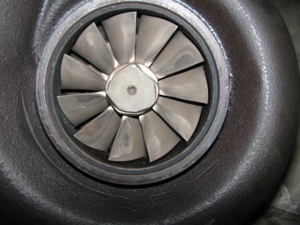 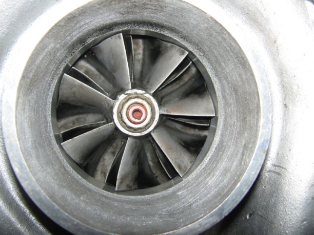 | ||
Richard Treacy Grand Master Username: richard_treacy Post Number: 2300 Registered: 4-2003 |
Stefan, Just as background for the puzzled, the exhaust turbine is never to be removed from the shaft once it has been fitted the first time, so maybe hence the funny staked fastener to discourage you. It is not necessary to remove the turbine from the shaft for overhaul. I assume that it is not a good idea to have a removable turbine or nut washing around in that tremendous heat and fiery gas. The picture below is an extract from my Garrett T04B book which shows that. You guessed it: I have never opened up a turbocharger yet. There are plenty of good shops which will overhaul you unit, but that would be cheating and less fun. Anyhow, I gleaned the following from some assembly notes. It implies that you may or may not have a 5/8� nut at the bottom. If not, as with yours, it may be held in a vice while you undo the compressor nut. Is that a possibility ? It look like it from the photos you have posted in light of the following text: >>>>>>>>>>>>>>>>>>>>>>>>>>>>>>>>>>>>>>>>>>>>>>> � Remove all of the turbine housing bolts except for the two at the top and bottom of the housing. (across from the oil feed-in line and oil outlet) These two screws will hit the center section and be used as "jacking" screws to push the turbine housing off of the center section. � Back both of the above bolts out until they hit the center section. Continue to alternately turn each bolt about 1/4 turn until the center turbine housing is separated form the center section. NOTE: The turbine housing needs to come off the center section parallel to the turbine wheel. If allowed to come off crooked it will bind on the turbine wheel and possibly damage it. After EACH 1/4" turn try and turn the turbine/compressor wheel. It will bind a little during this part of disassembly. TAKE YOUR TIME ON THIS STEP. If the binding seems excessive turn the bolts back in and try again. More penetrating lubricant may also be needed. � Remove compressor housing by removing the 13mm bolts and metal retainers. Keep an eye out for an 'O' ring around the outer diameter of the compressor seal plate. This 'O' ring can be re-used if not damaged. � Mark the compressor wheel and turbine wheel so they can be lined back up when reassembled. (The turbine wheel and shaft are one single piece) � A 5/8" socket should fit the turbine wheel "nut". If it does not fit, CAREFULLY secure the wheel by this nut in a vice. � Remove compressor nut using 12 point 7/16" socket then remove compressor wheel. >>>>>>>>>>>>>>>>>>>>>>>>>>>>>>>>>>>>>>>>>>>>>>> Hmmn. RT. 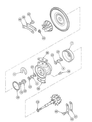 | ||
Stefan Morley Prolific User Username: myupctoys Post Number: 251 Registered: 7-2009 |
Hi Richard, As always, thanks for the input. Never simple is it. Was speaking to a bloke who used to service Diesel locomotives, in relation to Turbo's. Told him about finding no seal in the compressor and he suggested if the compressor is in anyway leaking there are significant flow on effects. Air leaking creates turbulence which breaks the clean air flow path loading up turbine. Apparently it doesn't take much of a leak to see significant issues. Don't know why someone left it out in the first place. Infuriating. What I'm thinking is replace this seal, then hope the small amount of movement in the bearings is acceptable and put it all back together. Have the right seal in the rebuild kit I bought. Worst case it will give me a breather to decide to get a full rebuild done. Best case it all works. Thanks Stefan | ||
Stefan Morley Prolific User Username: myupctoys Post Number: 252 Registered: 7-2009 |
Richard, This is the hex molding that would make life so much easier. Glad my blades don't look like that one. http://i257.photobucket.com/albums/hh203/dadasracecar/paper/turbinewheel.png Oh well. See how the seal goes. Stefan | ||
Stefan Morley Prolific User Username: myupctoys Post Number: 253 Registered: 7-2009 |
Richard, You asked about putting the exhaust turbine in a vice. Not very easily at all. This photo shows a better perspective. The outer end of the turbine is almost level with the exhaust flange and the blades are recessed about 5.5mm. Not a great deal of meat to get a vice onto and no room for slipping and no opposing flat surfaces. 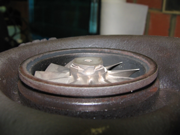 The seal I'm talking about isn't in the diagram you posted. It mates between the outer compressor housing and the large disc seen in the diagram. Touch wood the seal will improve matters. Cheers Stefan | ||
Stefan Morley Prolific User Username: myupctoys Post Number: 254 Registered: 7-2009 |
Hi, The rubber compressor seal did nothing. Gritted my teeth and spent most of the day rebuilding the turbo. New bearings and seals throughout. The compressor to oil gallery metal sealing ring was cracked and the turbine one looked worn. Scoring on the outside of the bearings as well. The shaft looked good thank god as do the blades. Hardest part of the job was removing the turbine housing. Took two hours tapping the housing and spinning the turbine to make sure it wasn't binding. Just about all done and a quick test in the garage at 2000 rpm and I'm fighting to keep my hand on the turbo outlet. Last time I loaded the turbo like that up the pressure disappeared instantly. Looks positive. Will know tomorrow. BTW the two turbo kits I bought (just in case) both had compressor nuts that go the wrong way for our cars. Apparently new Garrett turbos have a left hand thread. Re-used my old one with some lock tight. Stefan | ||
Stefan Morley Prolific User Username: myupctoys Post Number: 257 Registered: 7-2009 |
Hi, Thought people would like to see what the bits look like. The most difficult part was removing the the turbine housing. Patience using a rubber mallet whilst rotating the turbine to ensure it didn't bind on the housing. If you tackle the job make sure you scribe a mark indicating the relationship of the compressor to the turbine on the shaft for re-installation. Note on the removal of the compressor nut. Apparently newer Garrett Turbos have a left hand thread, mine was a Right hand thread. 88 vintage. The other thing is when you have the turbine in the vice and undoing the nut use a T Bar style wrench to apply rotational force around the axis. IE a spanner will cause problems. You don't want the blades broken. Only other hassle I had was one of the bolts on the turbine housing refused to undo. Ground it off then re-drilled and tapped a new thread. Amazing I managed to re-drill the hole exactly in the center of the stuffed bolt. Followed the old thread perfectly. Amazing stories. Toughest part of the job, turbine housing removed. 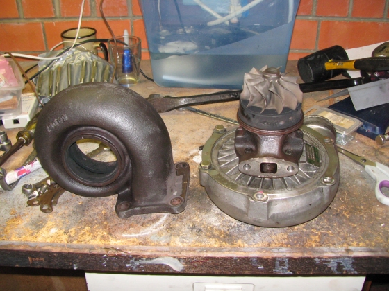 Compressor Nut removed 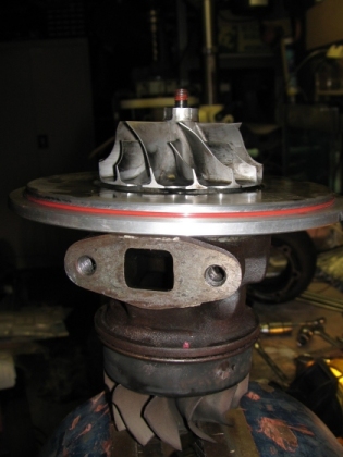 Old bearings 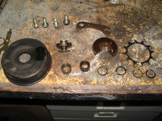 New bearings and all cleaned up 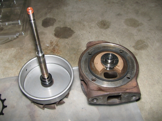 All done 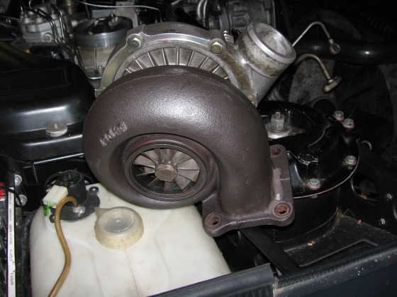 Cheers Stefan | ||
Stefan Morley Prolific User Username: myupctoys Post Number: 258 Registered: 7-2009 |
Hi, BTW Do not forget the small metal rings at each end of the shaft. They don't look like much but they are the seals between the compressor and oil gallery and turbine and oil gallery. I bought two kits from Ebay in Japan. One was better quality than the other. Search for "Turbo Rebuild Kit Garrett T3, T4, T04B, T04E (Dynamic)" and "T3 T4 TURBO REBUILD KIT VL R31 RB30 T04E T04B GARRETT". Latter of the two was better quality but both gave me room to move just in case. The nut was wrong in both kits. Cheers Stefan | ||
Stefan Morley Prolific User Username: myupctoys Post Number: 259 Registered: 7-2009 |
Hi, On last thing. Removing the turbine housing, the way I did it was totally remove three of the bolts. Then bit by bit slowly undo the remaining three bolts whilst tapping on the housing and rotating the turbine. The bolts stop you going too far once things start moving. It is quite critical to prevent stuffing up the blades. The compressor end is easy in comparrison but similar process will prevent dameage. Once I fix my leaking EHA shold be able to give the old girl a blast. Cheers Stefan | ||
Richard Treacy Grand Master Username: richard_treacy Post Number: 2304 Registered: 4-2003 |
Stefan, that is really great stuff. I assume that the turbine and compressor housings may be rotated relative to eachother. As your car has an intercooler it has the two 90% different from mine which has no intercooler. Time to give it a go myself. A question. Is there any choice of bearing types � whitemetal, roller, ball ? I must say that whatever mine has is fine after 320,000km+. However, it may be time to overhaul the turbocharger for good measure. By the way, I am tempted to carve up some pistons to drop the compression ratio to 5:1, then double the boost. The 8:1 compression on our cars is the limiting factor when it comes to boost. I have pushed mine to the limit of V-Power fuel as the octane rating of the Australian blend is too low. It was better on Europe's 100 ROZ stuff. On full demand, it tends to drive on the knock sensors, and that�s not really a good thing. With 5:1, it can emulate a 14 Litre naturally-aspirated engine with whatever horsepower you dial up without fears of detonation or piston overheating. Dreams ! RT. | ||
Stefan Morley Prolific User Username: myupctoys Post Number: 260 Registered: 7-2009 |
Hi Richard, Yes the turbine and compressor housing can be rotated relative to the bearing housing. The only limiting factor is the 270 degree bearing plate needs to be in a certain orientation, you can't get it wrong though. No I don't have the inter-cooler. That came in in 89. So what you see in the pictures would probably be the same orientation of yours. Mine was white metal. Only reason you'd want ball/roller bearings is faster spool up. But you'd need to be meticulous with your oil changes. Seen a few Spura's with larger than stock turbos and to help with the lag they use ball bearings. Is it really worth it when you got 320k. I'll be happy when my old girl is back to stock performance. Blasted EHA valve. Reading on the Merc forums its a known issue also a known cause of car fires. Apparently the biggest killers of both the fuel distributors and the EHA's is Ethanol blends. Newer diaphragms and rubbers are designed to cope but the older cars aren't. Hopefully its only my EHA. Cheers Stefan | ||
Stefan Morley Prolific User Username: myupctoys Post Number: 261 Registered: 7-2009 |
Richard, The inner bearings looked like brass, the 270 degree end bearing looked like sintered bronze and the end bearing looked like stainless or something looking like that. The seals at each end where light grey metal slightly rough surface. One of the old seals was broken and the metal is quite brittle. Then standard looking cir-clips. I've never run Ethanol blends but who knows what past owners did. In Oz if your above 98 RON you're probably using an ethanol blend. Causes the older rubbers to swell. Hopefully this is not the problem with my EHA, if it is the problem is almost certainly in the distributor as well. Hope not. Stefan | ||
Stefan Morley Prolific User Username: myupctoys Post Number: 262 Registered: 7-2009 |
Hi, One other useful little tit-bit. You don't need to undo the turbo heat shield mount on the timing cover, or remove the top radiator hose as stated in the manual. The top part of the heat-shield has two nuts on it and can be removed. Just push bottom part of the heat-shield out of the way with the remaining flex. Keeping the radiator hose on actually helps keep this out of the way. The V Clamp on the exhaust coupling needs a solid tap to break rotate it. Not hard just in the right direction. Gets caught up in the scroll of the turbine when tightened and needs to be moved back to a better position to be able to release it from the entire circumference. Have fun. Stefan |