| Author | Message | ||
Miguel A. Garcia Prolific User Username: magarcia Post Number: 111 Registered: 3-2005 |
Hello, last week the temp clock of SRH3430 started to fail reading. With contact key off, it remains death as all other clocks. Once the contact is switched on it turns up to mark "Zero". The same whith engine running. But it does not go up more than "zero" with the motor warm or even hot while running in the road, so i think that the problem is in the probe. It is (if i am confused, please let me know) in the expansion tank, and it is for the coolant level and temperature measuring, is it? Well, i have seen that it is clamped with an "o" ring, but once disconected the wires, and taken awy the "o" ring, i do not know how must it be taken way to be replaced with the new one that i have bought to Introcar. Is it screwed? i am afraid to broke it doing it in the unproper way, so first i should like to know how is it the procedure for replaciong. In the workshop manual is not any topic about this procedure, sorry. I have tested also that the the wires have electricty current with the key switched on, but wich would be the right voltage in them with engibe stoped? Thank you in advance. regards, Miguel | ||
Mark Herbstreit Experienced User Username: mark_herbstreit Post Number: 41 Registered: 5-2005 |
Miguel, to get you on the right track, if this is the probe you are talking about, it is coolant level only. It is held in place with a circlip. 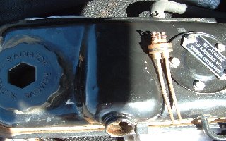 I would encourage every Shadow owner to check the function. The last time I checked mine it worked, however on the recent Darwin trip the radiator started leaking and it didn't work when I needed it most. While the man was fixing the radiator I took the probe out and cleaned it. I tested it by placing it in a bottle of water. Note low coolant light off.  Low coolant light on when removed from water. I would also replace o ring and circlip when cleaning. 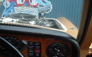 | ||
Miguel A. Garcia Prolific User Username: magarcia Post Number: 112 Registered: 3-2005 |
Yes Mark, this the probe that i say, but if it only is for coolantlevel, where is the temperature sensor that sends the information to the temp clock in the facia? Thank you | ||
Richard Treacy Grand Master Username: richard_treacy Post Number: 1032 Registered: 4-2003 |
The temperature transmitter for the analogue gauge is the lowermost probe on the thermostat housing of most models. Incidentally, the coolant level sensor probes drive a simple transistor amplifier located under the centre of the top roll. The probes, as Mark shows them, are simply a pair of thick bare wires, and not much can go wrong there. The amplifier for the coolant level is identical to that of the windscreen washer low level warning device where fitted as on later cars. The three transistors in the amplifier have a limited life, as do most 1960s semiconductors, but it is easily repaired. If the level probe plays up, usually but not always by illumination when it shouldn't, it is usually just necessary to replace the transistors at a cost of a few cents. Remove the top roll (surprisingly a very straightforward job), and remove the screw holding the amplifier to the dashboard frame. Using two BD138 and one BD139 transistors, change out the old ones and presto. Replace all the diodes with 1N4007 types while you are at it. 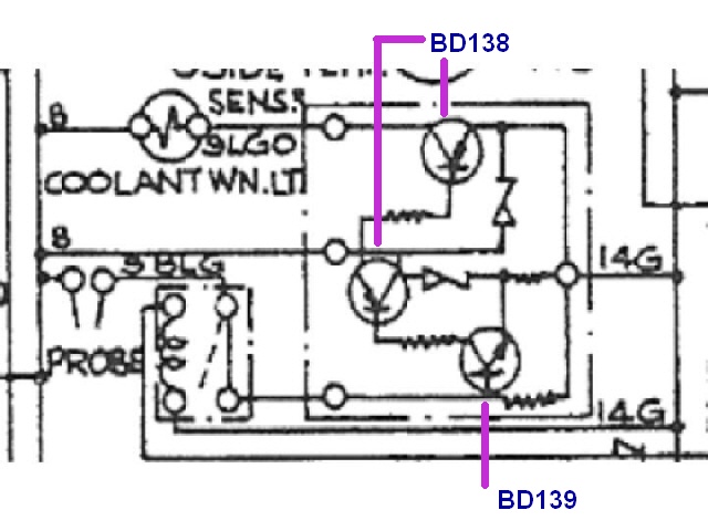 | ||
Miguel A. Garcia Prolific User Username: magarcia Post Number: 115 Registered: 3-2005 |
Thank you Richard. I have seen that in the down side of the thermostat of SRH13052 is located the probe that you say, but not in SRH3430. In this unit, the thermostat housing is clear of any hole or addon. Just the hose atatched to it, so really am confused about where is located the probe that sends the temperature data to the clock in the facia. I do not find it also in the CD�s workshop manual. Sorry for the insistence about it. regards, Miguel | ||
bob uk Unregistered guest Posted From: brig-cache-4.server.ntli.net |
There are three water "probes" one senses the temperature and the other which is in the header tank senses the water level. The third one senses cylider head temperature. the one in the header tank is at the rear of the tank held in by a circlip and covered with a dainty rubber boot-- 2 wires. Short these together and the low coolant light should alight. The temp one is either screwed into the inlet /water mainfold just below the stat or nearby in what appears to be the inlet maniflod which is also a water manifold. 1 wire. If this wire is earthed out by touching it on the engine the gauge should go hard over to hot. The temp sender is a standard Lucas jobby as fitted to loads of contempory Brit cars like BLMC-- Rover. If the gauge goes hard over then the sender or sensor is faulty and replace it. If you using a sensor that is not supplied expressly for a RR V8 then check that the threads are the same. The sender earths it self via the body of the sender. Sometimes I have found that by using the "wrong" sender that the gauge is well out because the resistance of the sender is wrong. In general Lucas only used one range of resistance for all there temp gauges for years. The water level one in the header tank are not so reliable and I always physically check the water. Lucas -Prince of Darknest and all that. The engine should run at between 85 and 90 celius. Brief excursions into the high 90s are allowed but prolonged running like this will cause a boil up. The sensor that senses the head temp is fitted to the right hand ( sitting in car) cylinder head this controls a buzzer (on my car) and goes off at 135 celius. Cylinder heads always run hotter than the water. If the buzzer goes off then the engine is king hot. This has one wire wwhich when earthed will set off the buzzer and a warning light ( depends upon which year the car is ) The cylinder temp idea is standard aero engine practice where the flight engineer would monitor the head temperature in flight so that he could adjust mixtures for maximum ecomony of feul without running so weak that the valves burn up, nowadays the flight engineer watches jet engines which have a whole load more sensors. I guess that RR Motors got this idea from RR Aero Engines. Because I have never seen a head temp sensors on any other car except RR. I have never had my engine go above 90 celius. If an engine starts to get a bit hot turn aircon off heater on and keep moving so air is coming through the rad if temp does not drop off then stop and check it out. My car which is UK based and 30 celius ambient is a hot day has never used water in 17 years. If I didn't change the antifrezze it would still have the factory water fitted. (Message approved by david_gore) | ||
Charlie J Unregistered guest Posted From: adsl-33-202-93.lft.bellsouth.net |
In regard to the cylinder head heat sensor it seems that on my Cornicne the heat sensor and thermostat controlling the radiator fan (electric in front of the rad) are in combination at the top right of the engine. The fan does not work unless I contact the two electrical leads together bypassing the switch/sensor. Can this unit be repaired or cleaned or must it be replaced? Or...is there a fuse to control these functions. Also my outside temperature sending unit is adrift under the right bumper. Is there a special bracket to attach it to the bumper and is the reading adjustable since it reads minus 20 in the summer? (Message approved by david_gore) | ||
Mark Herbstreit Frequent User Username: mark_herbstreit Post Number: 58 Registered: 5-2005 |
Charlie, are you assuming the electric fan should come on when the aircon is on "like other cars"?. It doesn't. I'm guessing your Corniche is late seventies or early eighties with a factory electric fan? If you have shorted the wires and the fan comes on then the fan circuit itself is working. The sensor is temperature dependant regardless of whether the aircon is on or off. | ||
Richard Treacy Grand Master Username: richard_treacy Post Number: 1127 Registered: 4-2003 |
I can't state that the Corniche or Silver Shadow II are exactly the same, but on my Turbo R the fans are switched on either by refrigerant pressure or by coolant temperature. The coolant temperature switch is the sensor on the thermostat cover (it measures the radiator coolant temperature, NOT the engine coolant temperature, as it is located after the thermostat). Both sensors definitely work fine on my car. Having said that, I have only ever noticed the fans come on twice over the years. On both occasions it was in standstill traffic and 35C plus general ambient, meaning that the engine heat and other traffic raise the the local ambient by the car to maybe 50C. The radiator is quite overdimensioned and does not really need the auxiliary electric fans at all. The coolant engine temperature (measured by the probe before the thermostat) never rises above just past the D in COLD in any ambient on my car, and the thermostat is new. The message ? By all means check the functioning of the auxiliary fans, but they have no effect above 10km/h. You may never witness them coming on even when fully functional. Even below 10km/h they are only a nice-to-have feature in extremely hot conditions when the refrigeration compressor is working hard. 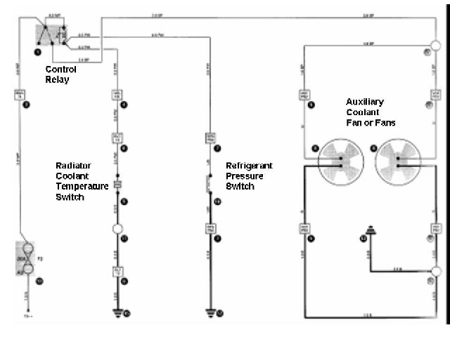 | ||
Gus Brogden Experienced User Username: gus Post Number: 14 Registered: 2-2008 |
My 68 shadow srx2838 is running a might cold. I put a Stant #13649 in my 77 shadow last spring and seemed to have no cooling problems at all. I realize both cars have a bypass, but it worked fine on the '77, even in 35 degrees. Is there any danger to this? Can I put one on my 6.2 L or do I need to get the factory gold/brass one? | ||
John Kilkenny Frequent User Username: john_kilkenny Post Number: 68 Registered: 6-2005 |
This is an interesting question. If you use a single acting thermostat like the Stant 13649, the radiator by-pass will remain open and only a percentage of the coolant will be pumped through the radiator. You would expect that the coolant could overheat in this situation. (See Tee One Topics Issue 61) However if the radiator cooling efficiency is such that the primary thermostat never becomes fully open when a dual acting thermostat is used, the single acting thermostat will try to compensate for the open by-pass by opening further and may be able to maintain the coolant temperature at a reasonable level. However this is not to be recommended, as on a very hot day, with the aircon in operation or an extended period of idling, coolant overheating is likely to occur. While the cost of the recommended RR thermostat seems outrageously high there is the 'peace of mind' factor to be considered. I would not take the risk with my car. | ||
Nigel Johnson Yet to post message Username: nigel_johnson Post Number: 1 Registered: 12-2008 |
Hello everyone, first post so here goes. The temperature gauge sender is located at the rear of the B bank cylinder head on CRH11939, a 1971 Corniche.Its a right beggar to get at, you will need a 5/8 AF spanner at least a foot long. And you can only get at it from above, which entails climbing on to the engine. Best of luck. Regards, Nigel. | ||
Dave Puttock Experienced User Username: ariel Post Number: 29 Registered: 5-2010 |
Just investigated my level probe amplifier, with a view to replacing the transistors but I find that two of the resitors are very brown (presumably overheated, one of them the wire detached as soon as I touched it. Can anybody confirm the resistance values or give me the colour codes as I think the best policy would be to replace every component. | ||
Richard Treacy Grand Master Username: richard_treacy Post Number: 2549 Registered: 4-2003 |
They are not critical in resistance, but the following will do. Use a � W resistor for the 100 Ohm and 220 Ohm resistors, and the other two are not critical power-wise. From the top of the diagramme posted 29 June, 2006 , use: Top resistor: 100 Ohm (brown, black, brown), � W Second resistor down: 220 Ohm (red, red, brown), 1/2 W Third resistor down: 1k (brown, black, red) Bottom resistor: 1.5 Meg (brown, green, green) RT. | ||
Richard Treacy Grand Master Username: richard_treacy Post Number: 2550 Registered: 4-2003 |
ps: don't forget to replace the diodes while you are at it. Parts costs are trivial. The Jaycar chain in Australia does this stuff, but RS Components is worldwide. | ||
Brian Vogel Grand Master Username: guyslp Post Number: 339 Registered: 6-2009 |
This seems to be the thread on to which to attach these questions. 1. What size is the O-ring that seals the coolant level probe into the header tank? I've got a fairly extensive collection of EPDM O-rings from putting together various hydraulic seal kits and these should work just fine in this application. What I don't know is whether I have the correct size in my current collection or not. 2. If you pop the probe and clean the ends is there any treatment that can (or should) be applied to them to help limit corrosion? I'm guessing the antifreeze should probably take care of this, but it never hurts to ask. 3. Is there any reasonably easy way to test whether the probes are "working"? You can't do a simple continuity test with a multimeter, or you can't with mine, because the amount of current is just too low. I can even dip the tips of my multimeter directly in the header tank and still not get a continuity reading. Even though I suspect I have a bad amplifier it would be nice to have a way to check to see whether this particular part of the system is actually working or not. 4. If my low coolant light is now constantly on, even if the two wires for the probes are directly connected to one another, is that enough to assume a bad amplifier? I had placed both wires on one probe just to get the light to go out while working on other things, and that worked for quite a while, now even that doesn't work. The header tank is full. 5. What is the cohort's opinion on this article for Repairing the Silver Shadow's "Low Coolant" Warning Amplifier? Should I follow the instructions there but use Richard Treacy's substitutions instead, or is either method OK? Based on the pictures in the article I'm seeing only one diode. I'm presuming that pretty much any rectifier diode (such as those used for the RT Window Lift Improvement) can be used for this application. If that's not correct, what would I need here? If anyone in the U.S. has done this fix, do you know if Radio Shack has the electronic bits needed or do I need to order from Mouser Electronics or similar? Brian P.S. See Tee-One Topics, Issue 95 with regard to an alternative thermostat for SY/SZ cars. [Disclosure: I'm the third of the three authors for said article.] | ||
Jeff Young Prolific User Username: jeyjey Post Number: 138 Registered: 10-2010 |
Hi Brian, My header tank recently split a seam, so I'm about to move everything over to a salvage one, and happen to have the coolant probe O-ring to hand: 7/8" OD, 1/8" Dia. There's nothing to break on the probe itself. If it's mechanically intact then it should be fine. I think it's safe to assume the amp is dead. Replace the transistors and diodes in it. I used a BC107 for the sensor transisitor (so that I didn't have to change any resistors), BC327 for the two amplifier transistors, and 1N4007 for the flyback diode. The second diode is standing up in the picture. I used a zener for that one (since that's what mine originally had), but I'm not sure it matters. After replacing the components, give both sides of the board a shot of clear laquer to keep the damp out. Cheers, Jeff. | ||
Brian Vogel Grand Master Username: guyslp Post Number: 342 Registered: 6-2009 |
Jeff, Thanks much. Brian | ||
Brian Vogel Grand Master Username: guyslp Post Number: 343 Registered: 6-2009 |
Jeff, I realized after reading your post that I am unclear about which transistors and diodes are which. Here is an edited copy of the image from the repair document I'd posted, with the various transistors and diodes numbered or lettered. 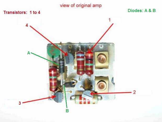 The only thing I am fairly certain about is that Diode A is replaced by a 1N4007 rectifier diode and Diode B was what you used a zener diode for. Would you mind clarifying this for me by filling in the following: Transistor 1 - BCXXX (function) Transistor 2 - BCXXX (function) Transistor 3 - BCXXX (function) Transistor 4 - BCXXX (function) Diode A - ??? Diode B - ??? Brian, who would rather get this right the first time (and is somewhat embarrassed to be unclear about this after some of the PCBs I've worked on in the past - most recently replacing two electrolytic capacitors on the power supply board for a plasma TV) | ||
Jeff Young Prolific User Username: jeyjey Post Number: 139 Registered: 10-2010 |
Hi Brian, Yes, Diode A is the flyback diode (1N4007) and Diode B is the zener (but it's possible a 1N4007 would work there too). I left Resistor 1 alone (so it's still 1M ohm). Transistor 2 is the sensor transistor (BC107), while 3 and 4 are the amplifier transisitors (BC327). Cheers, Jeff | ||
Brian Vogel Grand Master Username: guyslp Post Number: 346 Registered: 6-2009 |
Jeff, Bless you. I'll actually update the image such that this is included on it. Based on Richard Treacy's prior posts it looks like a 1N4007 diode should work for both applications on this amplifier. Just for my education, how does one know which one of these bits is a resistor versus a transistor? I'm imagining it's either the main body color or the banding color combination, but really have no idea. These bits appear to have been far more colorful "way back when" than they are now. (Of course, if it's from the logical diagram . . . [not yet really good at reading those]) Brian | ||
Jeff Young Prolific User Username: jeyjey Post Number: 140 Registered: 10-2010 |
Hi Brian, Only resistors have color bands. Diodes have a single band (to show which direction is which), but it's not usually in color. Once you look at the board up close, the transistors become easy to identify because they have 3 leads. (Resistors, diodes and capacitors generally have 2 each.) Cheers, Jeff. | ||
Richard Treacy Grand Master Username: richard_treacy Post Number: 2818 Registered: 4-2003 |
Brian, Diodes have a single band (stripe) at one end of the component, the cathode end. It signifies that conventional current flows from the other end � the anode � to the end with the stripe � the cathode. By the way, a 1N4007, EM513 etc is good for 1000 volts reverse off potential or more and 1 uA to 1 amp forward (on state) at 0,5 - 0,7V. Resistors usually have three main bands (stripes) plus one. The first three colour bands are black (0), brown (1), red (2), orange (3), yellow (4), green (5), blue (6) etc. The first two are numbers and the last the order of magnitude in ohms. For example, Brown (1) Black (0) Yellow (4) is 1 0 times ten to the 4, that is 100,000 ohms or 100K. The fourth and last band on a resistor is usually silver (ie within 10%) or gold (within 5%). If the fourth band is another colour, then the resistance value is more precise, eg grey is 0.05%. Great for colourblind people. RT. | ||
Richard Treacy Grand Master Username: richard_treacy Post Number: 2819 Registered: 4-2003 |
Jeff,
BC107s and BC327s - wow, they take me back to the 1970s. Fine, but I have been going for PN100 etc and sledgehammer BD139 / BD140 etc for a long time since, and even they are decades old. RT. | ||
Jeff Young Prolific User Username: jeyjey Post Number: 141 Registered: 10-2010 |
He he... yeah, I went digital around 1980, and then crossed over into software around 1984. What little remains of my hardware knowledge (empahsis on the little, sadly) is a bit dated. Cheers, Jeff. | ||
Brian Vogel Grand Master Username: guyslp Post Number: 347 Registered: 6-2009 |
Thank you gentlemen for this fascinating trip down "memory lane" of electronics. I don't know precisely why I find this sort of arcana interesting, but I do. I'll update the graphic to include the transistor numbers that Richard uses since by both your statements these are the more common/current of the numbering schemes. Brian, off to mow the lawn | ||
Brian Vogel Grand Master Username: guyslp Post Number: 348 Registered: 6-2009 |
Would this be the correct version "for posterity"?: Moderator's Edit: Incorrect image posted, author requested image replacement as below. | ||
Geoff Wootton Prolific User Username: dounraey Post Number: 170 Registered: 5-2012 |
Hi Brian Thanks for putting this up. It is really useful to have such information available. It appears that the Sensor transistor value has been clipped in the photo. If you need to make another iteration that value would be useful, although it can be gleaned from the text. Geoff. | ||
Brian Vogel Grand Master Username: guyslp Post Number: 349 Registered: 6-2009 |
Geoff, Strange since this is precisely the same image I used in the lettered/numbered version, but with the actual numbers filled in. It's entirely visible for me on the forum and in the original. I'll be happy to e-mail a copy to you. I'd still like to be assured that my diagram is correct from those that know before it circulates any further. If it's not I'll correct it and have any other versions deleted so as to minimize any possible confusion. Brian | ||
Geoff Wootton Prolific User Username: dounraey Post Number: 171 Registered: 5-2012 |
Brian Many apologies - I had mis-read it. Please ignore my last comment. Geoff. | ||
Brian Vogel Grand Master Username: guyslp Post Number: 350 Registered: 6-2009 |
OK, electronics people, since I already have a "did I get the right transistors in the right places" question I have a follow-up related to orientation of said transistors. In the original document (and I know that we wouldn't have to do this with the proposed transistors) the author states, "Please note that the new transistors have to be rotated 180�, because the collector and emitter leg are in opposite orientation." This leads to the question: How does one differentiate the collector from the emitter leg? The replacement versions of BC138 & BC139 transistors I can find are all flat like this drawing: 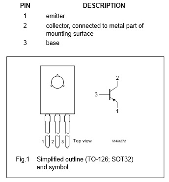 In all photos and drawings the legs appear to be of equal lengths and even in photos I haven't been able to discern what markings are on a transistor case that lets me know what's pin 1 versus what's pin 3 [pin 2 always being center]. Obviously it's essential that the correct pins go into the correct locations relative to the originals. How do you tell which pin is which on the originals and on the replacements? Brian, who's sorry for drawing this out, but who's cautious and anal-retentive about this as well | ||
Jeff Young Prolific User Username: jeyjey Post Number: 142 Registered: 10-2010 |
Hi Brian, For the replacements, the writing is on the front of the case. (I believe the three dimples or notches also mark the front of the case.) (And once you know the front, the drawing you posted shows the order.) For the originals, I traced out what they were connected to on the board to determine the orientation. For instance, for the sensor transistor: * the base is connected to the probe pin and a resistor * the emitter is connected to a resistor and a diode * the collector is connected to a resistor Cheers, Jeff. | ||
Brian Vogel Grand Master Username: guyslp Post Number: 351 Registered: 6-2009 |
Jeff, Bless you, as I can follow precisely what you've offered above. Do you by any chance have the same information for the amplifier transistors at hand? I intend to put in an order for some of these bits (which are dirt cheap) in fairly short order. If there are any readers in the U.S. that would like to have some let me know. I'll be happy to order extras and drop them in an envelope for cost. The postage for the things is far more expensive than the items themselves and I could probably order several hundred transistors and diodes and have them shipped for the same amount I'd be paying to have two sent. If anyone wishes to take me up on a "group buy" PM me with your e-mail contact info and mailing address. Brian | ||
David Gore Moderator Username: david_gore Post Number: 1272 Registered: 4-2003 |
In response to Brian's request, following is correct image: 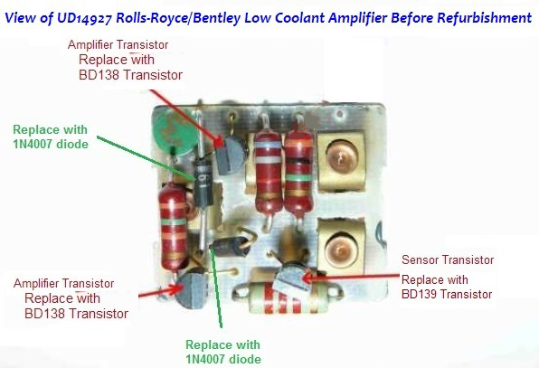 | ||
Jeff Young Prolific User Username: jeyjey Post Number: 143 Registered: 10-2010 |
Hi Brian, Amp transisitor #1: * base connected to a resistor (other end of resistor goes to sensor transistor) * emitter connected to a resistor (other end of resistor goes to base of other amp transistor) * collector connected to two diodes and earth pin Amp transistor #2: * base connected to a resistor * collector connected to warning light pin * emitter connected to a diode, two resistors and the +12V pin That's all from the schematic on page M4-20 of TSD4200, so I'm not sure which amp transistor is which, but it should be easy enough to figure out with the board in hand. Cheers, Jeff. | ||
Brian Vogel Grand Master Username: guyslp Post Number: 352 Registered: 6-2009 |
And after Jeff's input and "logic-ing things out" with regard to the photo, here's what I hope will be the fully annotated version as far as landmarks of interest for refurbishment. The additions are what pins/spades are which when you're looking at the circuit board from the components side. 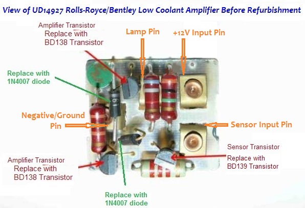 Brian P.S. Thanks again, Jeff P.P.S.: All of this is presuming that the labeling on the original photo of the refurbishment instructions I'd posted a link to are correct.} | ||
Carlos Magana Unregistered guest Posted From: 67.180.92.242 |
The coolant light and buzer go on even though the coolant level is fine. I have cleaned the probe at the header tank and tried to short the connectors and the warning light and buzer still stay on. Looks like I have to pull the relay under the dash and fix it. I can't seem to figure out how to disconnect and lift the dash to get to it, although this article says it's simple. How? Thanks (Message approved by david_gore) | ||
Paul Yorke Grand Master Username: paul_yorke Post Number: 1153 Registered: 6-2006 |
Carlos, have you checked the engine overheat sensor on the right hand cylinder head? Above A3 & A4 spark plugs? The low coolant light does not normally operate the buzzer. | ||
Brian Vogel Grand Master Username: guyslp Post Number: 700 Registered: 6-2009 |
Carlos, First, check what Paul has recommended. Then search these forums for the phrase "top roll" and/or do the same for the Tee-One Topics Archive. Removing the top roll, which is the upper front part of the dashboard under which the low coolant amplifier resides, is not a difficult task. I've done it multiple times and have probably posted about it. The procedure is also documented in the Workshop Manual, Chapter S10. Brian | ||
Hubert Kelly Prolific User Username: h_kelly Post Number: 113 Registered: 3-2012 |
Hi everyone, my header tank probe light is not illuminating when test button is depressed(I have not as jet checked the bulb). I have read the above txt , is there a test I can do to establish/eliminate the probe /amplifier unit. Many thanks Hubert Kelly | ||
Jeff Young Prolific User Username: jeyjey Post Number: 190 Registered: 10-2010 |
Hi Hubert, The test circuit bypasses the probe, so if it doesn't light on test then it's most likely the bulb or amplifier (or possibly one of the two test relays or the diode between them). Fig. M29 in the electrical chapter of TSD4200 shows the whole circuit. (This assumes a SSII or T2. I'm not familiar with the earlier cars.) Cheers, Jeff. | ||
Hubert Kelly Prolific User Username: h_kelly Post Number: 114 Registered: 3-2012 |
Hi Jeff, thanks very much for information supplied, I shall do a few tests over the coming days and report back. Many thanks Hubert Kelly | ||
Brian Vogel Grand Master Username: guyslp Post Number: 858 Registered: 6-2009 |
As an aside, I see I never posted the AS568 dash size for the coolant probe O-ring: -208 Thank you very much to Jeff Young for posting the necessary measurements way back on 2 May 2013. Brian P.S.: If anyone needs one in EPDM I still have a stash. PM or e-mail me. | ||
Randy Roberson Prolific User Username: wascator Post Number: 233 Registered: 5-2009 |
Great posts here: timely for me as I just removed my probe (in about 10 pieces) while refurbishing my Car's tank. That puppy was NOT coming out.I suppose the O-ring was so hard it would not give enough to come out. I tried everything I could think of, before finally resorting to that old familiar politician's friend: violence. | ||
Bob uk Unregistered guest Posted From: 94.197.122.82 |
Big hammers and determination win through every time. My little rubber boot perished, I found a similar boot on a Japanese starter motor which looks the part. If a whistle is fitted to the steam valves out let then the whistle will blow if the steam valve lifts. I had a mini that used to blow a bit of steam so I put the plastic overflow tube in the wing channel under the bonnet edge so when it blew I could see the steam and back off a bit. I thrashed that mini until it it's pips squeaked. (Message approved by david_gore) | ||
Richard Treacy Grand Master Username: richard_treacy Post Number: 3092 Registered: 4-2003 |
Interesting, but I preferred to buy the correct part UR15238 for just 20 quid (less than $40 in our money). | ||
Bob uk Unregistered guest Posted From: 94.197.122.89 |
Richard, I agree with the principal of buying the right parts. The boot does fit. It is an insignificant part that could be left off. I ran the car for 10 years with a perished one that sealed nothing. I think the idea is to keep damp out and putting the low coolant light on. The quality is good and it makes the wiring look tidy. The boot to me is a simple wiring sundry like a spade terminal and therefore any maker will do as long the quality is good. I don't care who made my rear light bulbs which are necessary unlike the rubber boot. I haven't a clue who made the original. (Message approved by david_gore) | ||
John Beech Frequent User Username: jbeech Post Number: 76 Registered: 10-2016 |
Brian, You recommend doing a search on top roll and let me tell you, on a forum about Rolls-Royce auto, THAT doesn't work very well. However, the tip to look in Workshop Manual S10 was perfect because on page S107 was the necessary diagram and instructions. Thanks! | ||
Brian Vogel Grand Master Username: guyslp Post Number: 2120 Registered: 6-2009 |
John, I presume that anyone who's familiar with doing searches of any sort knows how to add on additional search terms to narrow down results as needed. I also try to emphasize that virtually any question regarding how to take apart or put together any part of these cars can be found in the Workshop Manual, Tee-One Topics, or both. I put together an article, UD19427 Rolls-Royce/Bentley Coolant Level Amplifier Repair, based on the input from this thread and my own work using that input. Brian | ||
Geoff Wootton Grand Master Username: dounraey Post Number: 1499 Registered: 5-2012 |
I recommend everyone to download the above pdf file to their personal archive. This is the document I followed when successfully rebuilding my coolant level amplifier. The parts are readily available from any electronics supplier. Thanks for putting it up again Brian. I think it's a good idea to have a personal archive as documents such as these are often difficult to find after a few weeks have elapsed, just when you need them. Geoff | ||
Brian Vogel Grand Master Username: guyslp Post Number: 2121 Registered: 6-2009 |
Geoff, Unrelated to my own recent contribution, I strongly echo your sentiment about having your own electronic archive. Over the years I have amassed a huge personal electronic archive, a great deal of which was directly downloaded from the RROC-Australia Post-War Technical Library along with a great deal of "incidental and interesting" bits picked up from elsewhere. As far as the stuff from the technical library goes, and please do not interpret this as a criticism as I know it's the result of accidents of history and available technology, a very great many of the PDF files are image scans and, thus, not searchable. I've spent a lot of time running OCR processing on most of the files I use regularly, and many that I do not, so that finding what I'm looking for is much easier. Crewe (and they're hardly alone) had the annoying habit of placing critical information (at least to me) at times in sections as "asides" that are completely unrelated to where I'd first try to look for something. However, if you know the magic keyword, and often you do, *pop* - it shows up in a Windows search (provided you have file content searching enabled, which it is by default and has been since at least Windows 7 [I think]). Brian |