| Author | Message | ||
John Rowney Experienced User Username: johnrowney Post Number: 53 Registered: 02-2015 |
The following describes the procedure used to replace the original Lucas Opus internals in the distributor in my 1978 Rolls-Royce Corniche DRH32489. This was a UK delivery vehicle, but it has spent most of its life in Australia. Since it was a UK delivery of that vintage, it had a Solex 4A1 carburettor and some of the procedure below may only be relevant to this particular sort of vehicle. I am sure that others will advise whether this will be OK for other SY models. This replacement was necessary since the original Lucas system had completely failed and no spark was available for ignition. A classic �Failure to Proceed�.  DRH32489 in Failure To Proceed mode It was decided to eliminate the original ballast resistor, particularly since there was no understanding of what was to be done with the ballast resistor and the 6 wires going in and out of it. This meant replacing the existing coil with a non-High Energy Coil. The coil selected was a Bosch GT40 which replaced the existing Bosch GT40R (which is used with the ballast resistor).  Distributor with cap off 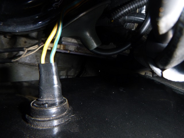 Ballast resistor top view  Plug into ballast resistor - passengers side The instructions which came with the Petronix LU-281 did not have specific directions for application in the Corniche or any other Rolls-Royce vehicle, so the following procedure was used. 1. Disconnect the wiring plugs from both sides of the ballast resistor. 2. Remove the ballast resistor by removing the two anchoring bolts. 3. Measure the distance required for a wire to connect from the driver�s side plug on the ballast resistor to the positive terminal of the coil. Cut the wire and install a male tag to fit one end of the wire into the middle space of this plug. On the other end of the wire, install a tag supplied from the kit. (This will be used later to provide 12 V power to the coil.) This temporary wire is required since the ballast resistor plug is in an awkward position to reach with a multimeter probe. 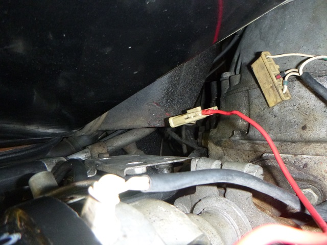 Installation of the temporary wire 4. Turn on the car ignition, and verify with a multimeter that full battery power is available at the wire tag on the temporary plug tapping. Turn off the ignition once the power source is identified. 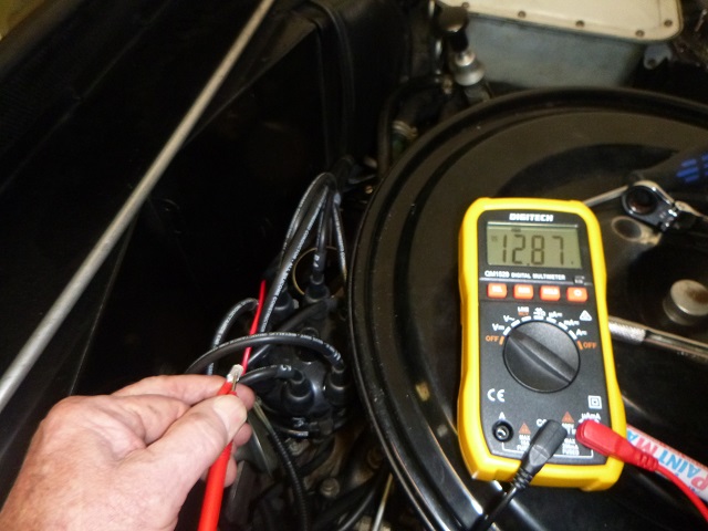 Checking that the supply voltage is OK 5. Using cable ties, fix the ballast supply plug to the plate where the ballast resistor originally was located. There may be a better solution, but this will work, but it will not look completely kosher to the enthusiastic RR owner. 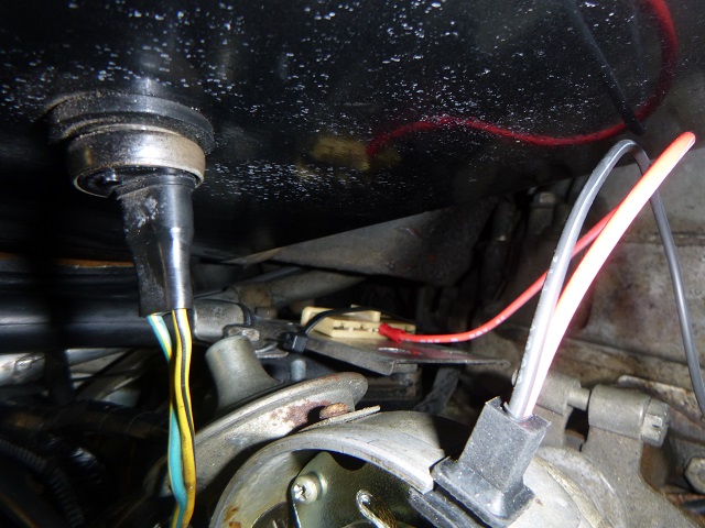 Power supply from original plug located with a cable tie 6. Remove the wires from the existing coil including the HT lead. 7. Remove the original coil and replace with the new GT40 coil. 8. Reinstall the condenser and reconnect it to the positive coil terminal. 9. Mark the distributor cap and all high-tension leads, so that if the leads are removed to make more room to work, they will be replaced in their original positions without much anguish. 10. Remove the distributor cap. 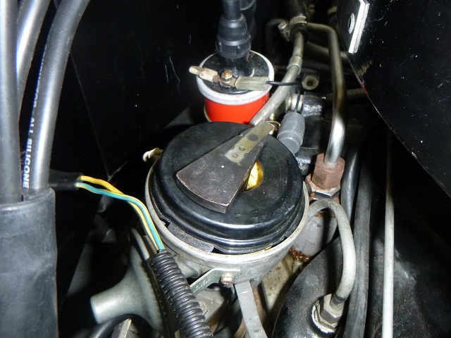 Distributor with cap off 11. Remove the rotor. 12. Remove the dust cap. 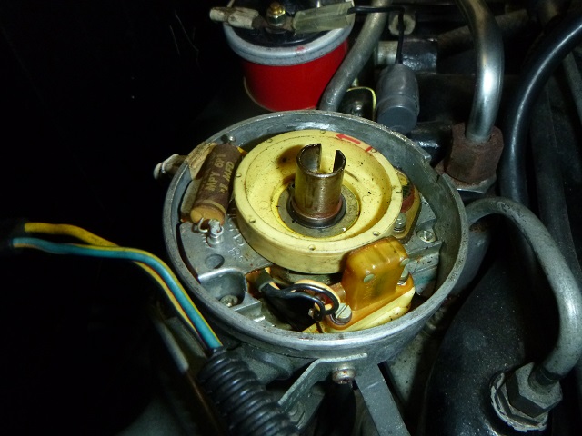 Distributor with rotor and dust cap removed 13. Remove the 3 Phillips head screws and small spring washers which hold the main distributor electronic equipment in place. 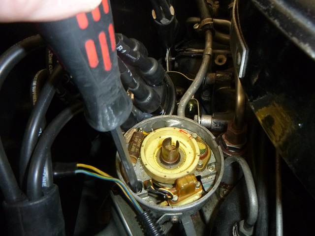 Removal of the Phillips head screws from the main plate 14. Remove the circlip, washer and O-ring from the distributor shaft. 15. Remove the plastic trigger wheel by pulling it off the shaft. 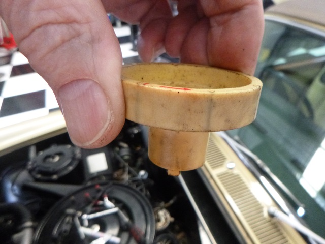 Removal of the Trigger Wheel 16. Remove the electronic assembly from the distributor. This is to be discarded. The system includes with wiring and the plug into the passenger�s side of the ballast resistor. 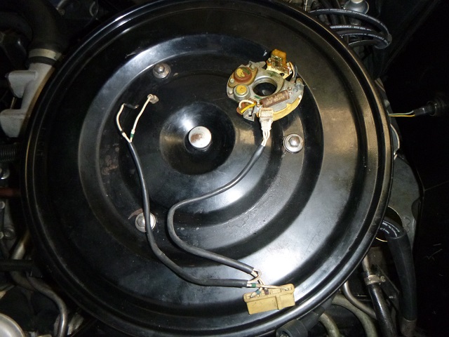 The original Lucas OPUS electronic system 17. Clean up the distributor housing and spindle. 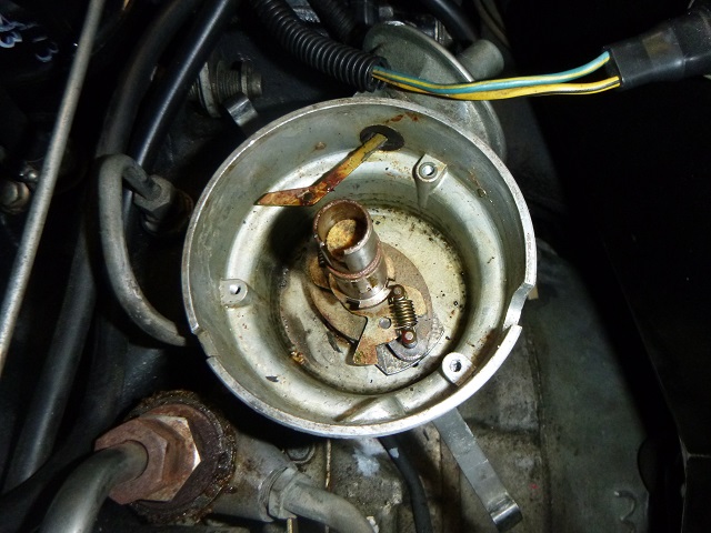 The distributor housing before cleaning 18. Install the new LU-281 ignitor plate assembly into the distributor, taking care to line up the vacuum advance pin with the vacuum advance arm. 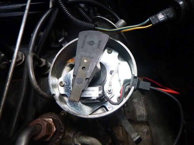 Ignitor system LU-281 and rotor in position 19. Using the original screws and washers: a. Attach the loose end of the earth wire to the nearest location. b. A small piece of blu-tac may be useful in helping locate the earth wire tag before using the screw to install the tag. This is very fiddly to connect up. c. Clean the blu-tac from the underneath of the tag before fully tightening the screw. d. Install the remaining 2 screws and washers to fully secure the ignitor and the plate to the distributor. 20. Slide the rubber grommet holding the black and red wires into the slot at the side of the distributor housing. 21. Attach the magnetic sleeve extender to the bottom of the distributor spindle. This black plastic fitting is the smaller of the two black devices supplied in the kit. One tooth is larger than the other 3 and must be aligned correctly. 22. Install the larger magnetic sleeve assembly � again, line up the larger tooth with the larger hole in the spacer below and press down firmly. 23. Install the rotor and then the distributor cap. 24. Connect the wire from the supply point on the driver�s side plug of the ballast resistor to the positive terminal of the coil. 25. The red wire from the distributor is then fitted to the positive terminal of the coil. Cut the red wire and fit a female tab to it and install on the positive terminal tag. 26. The black wire from the distributor is then cut to fit the negative terminal of the coil. The supplied tag will be fitted to the end of this black wire to make the connection. 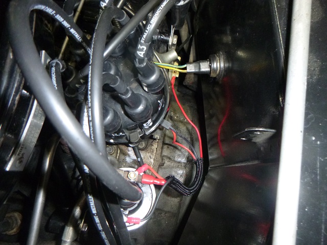 The final installation The new system is set to go. My new installation fired up first turn of the ignition, which was never achieved in the 6 years I have owned DRH32489. I welcome any comments about how to improve this procedure, particularly if you have a method that will hide the obvious wiring and ballast resistor changes so that the car will look just as it was built. I am just happy the beautiful machine is no longer in the FTP category. John Rowney | ||
John Rowney Experienced User Username: johnrowney Post Number: 54 Registered: 02-2015 |
Sorry, it has been a little while since I have posted something, and the captions were missing - I erroneously thought the title of the photo file would be given. The captions are as follows for each photo. 1. DRH3323489 in FTP mode. 2. Distributor cap off showing rotor and dust cap. 3. Obscure top view of the ballast resistor. 4.The plug on the passenger's side of the ballast resistor. 5.The wire connection to the power supply. The other plug is on the right. 6.Testing the supply voltage is OK. 7. The plug from the ballast resistor is cable tied in place with the new power lead connected. 8. Distributor with the cap off. 9. Distributor with the rotor and dust cap off. 10. Undoing one of the 3 Phillips head screws. 11. The plastic trigger wheel. 12. The complete Lucas Opus electronic assembly sitting on the air cleaner. 13. The distributor housing prior to cleaning. Note the vacuum advance arm. 14. The LU-281 system and rotor installed. 15. The final assembly. John - have added photo captions to your post above and have adjusted the formatting accordingly. Thank you for documenting this modification for our benefit. . | ||
Brian Vogel Grand Master Username: guyslp Post Number: 3015 Registered: 06-2009 |
John, Quite similar to my adventure installing the replacement Mallory distributor as far as figuring out wiring goes. I could have sworn I documented what's currently where in the engine bay and with the wiring, but I can't seem to locate that particular thread easily at the moment. Thank you very much for having taken the time to photo document your work and write up the step-by-step description of same. Brian | ||
Jim Walters Frequent User Username: jim_walters Post Number: 296 Registered: 01-2014 |
John, thanks for documenting the procedure with an excellent post. If you are going to toss the OPUS bits, could you mail them to me instead? I'm collecting parts like this for rebuilding. Thanks, Jim. SRH8505 SRC18015 SRE22493 NAC-05370 www.bristolmotors.com | ||
Philip Sproston New User Username: phil2025 Post Number: 37 Registered: 07-2006 |
John, the Petronix will work well plus give better fuel consumption but we do one better by replacing the whole distributor with an Australian built one using Bosch internals which we have tested to give 9% better fuel economy Phil Sproston | ||
Graham Phillips Frequent User Username: playtime Post Number: 236 Registered: 03-2019 |
G'day everyone,..... Got the model /part number for that Dizzy? Graham. | ||
Philip Sproston New User Username: phil2025 Post Number: 38 Registered: 07-2006 |
Graham give us a ring Phil 0418266631 | ||
John Rowney Experienced User Username: johnrowney Post Number: 55 Registered: 02-2015 |
Jim I wasn't actually going to toss the OPUS system - I always keep things, so sorry I can't send it to you. I am hoping some bright spark will come up with a method for replacing the ballast resistor and plugs so that the system still looks original. This is a long term aim, since I will be putting the engine back in my 1938 Wraith WXA68 soon. Philip, Due to the rather large job on the older car, I won't be looking at any more work on the Corniche, apart from fixing the air leak in it which happened suddenly just before Christmas. I have already replaced the coil, condenser and HT leads, and now have replaced the electronics as described in this post. I have a new Solex gasket kit and start this today - hopefully all will be fixed before WXA68's engine lobs in my shed. John | ||
Jim Walters Frequent User Username: jim_walters Post Number: 297 Registered: 01-2014 |
John, here is an article on rebuilding the Lucas OPUS module: http://35de8ignitionrepair.eu5.net/ SRH8505 SRC18015 SRE22493 NAC-05370 www.bristolmotors.com | ||
John Rowney Experienced User Username: johnrowney Post Number: 66 Registered: 02-2015 |
After advice from Steve Sparks (see the postings on the Solex 4A1 carburettor needle seat), I purchased a Petronix Flame Thrower coil from Pro Quip on the net. It was a convoluted path to determine which coil I should use, but it ended up being a 1.5 ohm 40,000V model. Delivery was quick - after ordering it on Tuesday afternoon it was in my PO Box on Thursday morning. I don't think I have noticed any change in performance, but hopefully every component will last a good while. | ||
Mark Aldridge Frequent User Username: mark_aldridge Post Number: 668 Registered: 10-2008 |
John, ensure Flame Thrower coil is mounted vertically, they do not seem to like horizontal mounting. I have had 2 coils fail on my MG and can only guess it is due to the mounting angle. Mark | ||
ross kowalski Prolific User Username: cdfpw Post Number: 1351 Registered: 11-2015 |
John, The maximum voltage a coil can make is a function of it's windings, the voltage that a coil actually makes in your car is a function of the environment in the combustion chamber. The resistance of the coil effects a faster charge time of the coil. In a low compression / low rpm engine like the RR v8 any coil would function identically. The higher voltage potential of a high output coil allows larger plug gaps which is necessary when running lean mixtures. Modern cars all have relatively high output coils because of fuel economy requirements. I am running a coil that came off an international harvester tractor in mine and it idles as smooth as you want and drives just fine. I would however, add that I would only buy high quality coils from trusted manufacturers, you might not need a high output coil, but need one that works. | ||
Robert J. Sprauer Frequent User Username: wraithman Post Number: 632 Registered: 11-2017 |
Has anyone installed a Pertronix in a fuel injected RR/B? I'm having issues with keeping the motor running after it starts. I think the ECU wants to know the motor is turning over. | ||
michael vass Frequent User Username: mikebentleyturbo2 Post Number: 683 Registered: 07-2015 |
Have you checked the 2 crank sensors? | ||
Jeff Martin Experienced User Username: jeff_r_1 Post Number: 120 Registered: 07-2018 |
He found the solution. https://www.rollsroyceforums.com/threads/pertronix-install-use-9br-ballast-or-not.29055/page-2#post-195625 | ||
Robert J. Sprauer Frequent User Username: wraithman Post Number: 633 Registered: 11-2017 |
Michael, There are no crank sensors on a 1980 Silver Wraith II that is fuel injected. The original Lucas 9BR had to be used due to the engine running sensor. The project went well. Works great. Thanks | ||
KevinBacon Unregistered guest Posted From: 2.25.159.249 |
I would have thought using the feed to the ballast resistor as above means that the feed to the weakener and anti diesel solenoids is lost. I freely admit though that car electrics are a mystery to me especially the complicated arrangements Rolls Royce seem to love using. (Message approved by david_gore) | ||
Brian Vogel Grand Master Username: guyslp Post Number: 3317 Registered: 06-2009 |
Neither of these exist in a fuel-injected engine, and that was the context of the referenced post in rollsroyceforums.com. Both of those are only pertinent in cars with carbs. | ||
Daniel Shepherd New User Username: 1957_grey_cloud Post Number: 24 Registered: 12-2021 |
Thanks for sharing - we need to get around to doing this to our '74. | ||
Kevin Bacon Yet to post message Username: bacon13 Post Number: 1 Registered: 11-2022 |
A nice clear and easy to follow thread. I fitted a Petronix to my Shadow 2. The hardest part being joining the feed to the terminal block that previously went to the resistor contraption, as the wires were already short. I previously replaced the rotor arm as, when hot it seemed to short out at high revs cutting the engine. I replaced it with an old stock genuine Lucas one, I understand failure of the cheap unbranded rotor arms is quite common. I had wondered (see my previous post) if doing away with the resistor block would stop the feed to the solenoids (weakener and anti diesel) but they are in fact fed without going through the resistor block. I noticed the Petronix gives far less scatter, seen via a timing light, presumably this was due to the original unit starting to fail. | ||
Robert J. Sprauer Frequent User Username: wraithman Post Number: 812 Registered: 11-2017 |
Leave the Lucas component in place. You need the ballast. You may want to swap out the coil as well. I use Pertronix I and II in the RR's here. Much smoother idle and acceleration. | ||
Alan Dibley Frequent User Username: alsdibley Post Number: 363 Registered: 10-2009 |
"Much smoother idle and acceleration." Robert, compared to what, points or other electronic box? I am in the middle of dithering about whether to go electronic. Alan D. | ||
Kevin Bacon New User Username: bacon13 Post Number: 2 Registered: 11-2022 |
I did away with the resistor as per recommendation from Petronix, the coil was suspect and replaced with 3 Ohm one also as rer their recommendation. |