| Author | Message | |||
Glen Poolen Experienced User Username: wgipps Post Number: 190 Registered: 03-2018 |
Afternoon all. 1974 Shadow 1 SRH17903. Can anyone help with these 2 engine bay connection plugs please. 1 driver side and 1 passenger side. There are broken/damaged/cut wires on each of them visible in the pics. I'd like to get them repaired. Is anyone able to provide a diagram or description of what wire is what? 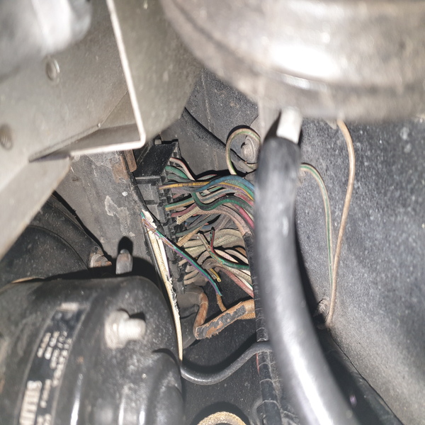    . | |||
Jeff McCarthy Frequent User Username: jefmac2003 Post Number: 633 Registered: 05-2007 |
The practical wiring diagrams in the manual will have the pin-out. It's a pain to read. The cut wires means someone has "fixed" something in the past. Hopefully by just running a new wire without unravelling the loom. That purple/green wire in the top photo looks a worry - is that exposed copper I can see? That should be the first thing you fix. It probably looks worse than it is. Write down the colour of any cut wires to figure out what circuit it belongs to. Also note if it's on the nearside or offside. I'm about to go out but I'll keep an eye on this thread over the weekend. P.s. my car is in Melbourne for major work. The bill so far is $27,000 !!!!! Complete rebuilt engine and auxilliaries. Now I discover someone left a spacer washer out of the diff gubbins sometime in the past and I've had a "free-floating" thingamajig with teeth rattling around inside the diff for the last 12 years. Aaaaargggghh!! I think I'm | |||
Geoff Wootton Grand Master Username: dounraey Post Number: 2159 Registered: 05-2012 |
I can't help with an actual connector diagram however I find the attached file useful in conjunction with the wiring diagrams when trying to figure out electrical problems.
| |||
Glen Poolen Experienced User Username: wgipps Post Number: 191 Registered: 03-2018 |
Thanks Geoff Wow Jeff - its gonna be good for another 50 years!! don't worry about the thingamajig - I think I've got a spare here somewhere!!  The practical wiring diagrams! Good God! It gave me seizures just looking at it! http://rrtechnical.info/SY/TSD2476/Version2/21.pdf - RHD cars from serial 9000. Section 9 page 153 - sheets 1 to 4. I'm going to suggest that the original documents these are a large wide single document that you pull out? If so - does anyone have it in its original size? I'm sure that it can be reproduced easily enough - let me know and I'll see what i can organise so we can put it up here for people to print out at their leisure. Its a pity the photos uploaded here are small - on my computer I have really good zoom ability. And for some reason this site spins them on their side - so i apologise for neck injuries viewing the pics. Anyway, sheet 1 from that set mentioned. The drivers side bank has 6 plugs with the ability to hold 9 wires each - but it doesn't appear that any of them have the full 9 wires in them. There's 3 cut toward the plugs, 2 cut further up the loom and that purple/green exposed copper wire across the top. On the passenger side (plugs and surrounding appear dirty) there is again 6 plugs in the one bank. There's about 5 wires cut back up the loom (just visible past the tape) and a few cut down near the plug. I've flipped several coins, consulted a psychic, had my palms read and have concluded that the attached diagrams are the plugs in question. The left hand toeboard are the drivers side plugs as they have the single (9th) wire at top. I can't see the single wire on the passenger side set so I am assuming its because its at the bottom of the plug. Feel free to correct me if I am wrong!     . | |||
ross kowalski Prolific User Username: cdfpw Post Number: 1261 Registered: 11-2015 |
Glen, Hear hear on the fold out full sized paper ones from the manual. Way easier when tracing down wires. The half page scans were likely done because they fit on a home scanner. I'll try and scan some this weekend for you. | |||
David Gore Moderator Username: david_gore Post Number: 3481 Registered: 04-2003 |
Ross, Yes - I only had an A4 high quality scanner when I made the high-resolution version of TSD2476 in the Technical Library in 2004. It was my intention to make a composite page from the individual scans using Photoshop however other problems intervened as a consequence of being self-employed and this intention became low priority. Larger scanners at the time were very high priced commercial units outside my ability to purchase one. | |||
Glen Poolen Experienced User Username: wgipps Post Number: 192 Registered: 03-2018 |
Can anyone provide the dimensions of the full sized ones - ill make some enquiries as to scanning and printing. | |||
David Gore Moderator Username: david_gore Post Number: 3483 Registered: 04-2003 |
Glen, I no longer have access to the printed TSD2476 I used for the original scans however I am reasonably certain they were a standard A3 size or an A2 if my initial guess is incorrect. | |||
Martin Taylor Experienced User Username: martin_taylor Post Number: 164 Registered: 07-2013 |
I have a reasonable copy scanned to PDF from the manual, where do I send it? | |||
ross kowalski Prolific User Username: cdfpw Post Number: 1263 Registered: 11-2015 |
Martin, Is your scan the complete wiring diagrams? ( Meaning each diagram is a single image) not I was planning on scanning up those diagrams at 600 dpi this AM. Let me know and I'll be able to save that time. Thanks | |||
Trevor Hodgekinson Experienced User Username: wm20 Post Number: 92 Registered: 11-2006 |
The manual pages would be B2 or B3 as it predates the standard A sizing. Most instant print shops will have a large flat bed scanner of some sort. The Artview are the best , used of course for scanning art. However an instant print shop should be able to stitch the PDF images together and print them out at any size Photoshop 9 and newer should have auto stitch ( might be called panoramma) but the images will need to be raw format from memory | |||
ross kowalski Prolific User Username: cdfpw Post Number: 1265 Registered: 11-2015 |
Martin, I scanned all the wiring diagrams this AM as 600 dpi PDF files. It was a test of the scanner quality. They look really good I then went back, put everything in proper order and started scanning the complete document with divider pages and index pages and sure enough brownout resets the scanner and it won't restart. ( Maybe it will eventually but after 30 min on the third restart attempt I was done) | |||
Glen Poolen Experienced User Username: wgipps Post Number: 193 Registered: 03-2018 |
What size is the original in the manual? | |||
Martin Taylor Experienced User Username: martin_taylor Post Number: 165 Registered: 07-2013 |
https://drive.google.com/file/d/16fKT3wTnQUdpyALi_l-f-7v-EME9VR9U/view?usp=sharing This is the wiring diagram for 72-73, suits most, scanned from the FSM | |||
Martin Taylor Experienced User Username: martin_taylor Post Number: 166 Registered: 07-2013 |
That was scanned in a printing shop, I also made a few laminated copies, should be zoomable etc, let me know if it doesn�t work | |||
David Gore Moderator Username: david_gore Post Number: 3487 Registered: 04-2003 |
Martin. I downloaded your sample and found it fully legible with some mild pixellation at 800% magnification using Adobe Acrobat. | |||
Glen Poolen Experienced User Username: wgipps Post Number: 194 Registered: 03-2018 |
Attached are stitched pdfs. This will be - i would suggest - the most common Shadow wiring diagrams from Aust and UK. They dont print well - on A3 they are too small and cant be read. They arent scanned with high quality enough to print out on a large format printer. They do zoom in on a computer quite well - so at least they are in 1 single document for now
| |||
Jeff McCarthy Frequent User Username: jefmac2003 Post Number: 634 Registered: 05-2007 |
Glen most big storefront printshops have printers for (about a metre) wide rolls of paper. I did this years ago and got it laminated. It has saved me so many, many hours of headscratching frustration that it was worth the couple of hundred bucks - most of that for laminating by the way.Ends up about 2 metres wide. I used the theoretical wiring diagrams from this site as they're really sharp & high res - unlike the practical ones. Unfortunately my paper manuals are photocopies so not as good. | |||
Jeff McCarthy Frequent User Username: jefmac2003 Post Number: 635 Registered: 05-2007 |
Just had a look at your PDFs - I'm taking those straight to the printshop. Well done! | |||
Glen Poolen Experienced User Username: wgipps Post Number: 195 Registered: 03-2018 |
If you can print them out on big paper let me know. A3 is too small to read. A1 migh come out better but the image isnt sharp enough and all you might see is black blurs where the writing is. If we can find an original set that we can scan with high DPI we are gonig to be on a winner. | |||
Trevor Hodgekinson Experienced User Username: wm20 Post Number: 93 Registered: 11-2006 |
The rip application on most large format printers can scale PDF's to keep them sharp. I used to have an A2 machine and I could blow up very small adds to very large sizes . The down side is the more fiddling the print shop has to do the more expensive it will be. You might find a poster printer will be better value You should be able to get it output onto vinyl for around $ 50 . The go to an art supply and get a roll of acid free paper and roll it up with the acid fee which will stop it transferring to the back if it gets too hot & humid. The go is to allow them to use whatever media they have so they can tack it on the back of another job or use a short length of a roll that would otherwise have become scrap. | |||
Trevor Hodgekinson Experienced User Username: wm20 Post Number: 94 Registered: 11-2006 |
And gracious thanks to both David & Glen to make these available | |||
Glen Poolen Experienced User Username: wgipps Post Number: 196 Registered: 03-2018 |
thanks Trevor. I would like to get them blown up to the best size available - certainly on soft copy so people can take them and get them printed to whatever size as needed. Thus far the whole exercise has cost me $0.80 - so im happy to keep going. My cousin has a commerical print operation so im hoping I can call on him in the near future but I need good quality scans. | |||
Glen Poolen Experienced User Username: wgipps Post Number: 197 Registered: 03-2018 |
Ok - so along I go with my problem and this is what I have found. 1 plug on each side is the most serious of problems with cut wires. Right Side Plug F. All "Relay PC Socket" except UP which is a "Relay Valance socket" GBP Switchbox 11, Gearchange Actuator, Rear Demister, Rear Demister, Relay & Switch, Wiper Switch, Intermittent Wipe Control WRP Neutral Start Switch, Starter Relay, Choke-On Start Relay, Heater Switch, Water Tap Relays WUP Thermal Delay Switch (for Choke), Choke Solenoid, Stop Light Relay, Stop Light Warning Lamp, Compressor Clutch, Water Tap Relays, Suction Throttling Valve Actuator UP Rear Demister Relay, Wiper Switch, Wiper Motor, Wash Wipe Control, Headlamp Safety Relay, Headlamp Safety Cut-Out, Refrigeration Switch YPP Water Tap Relays, Refrigeration Switch  In the picture, the wires have been cut at the plug and at the loom - which explains all that. The red wire in the middle is just hanging on so it will need to be repaired as well. Left side Plug M. All "Gearbox Actuator Plugs" BNP Gearchange Actuator, Gearchange Selector Switch, Auot Park Relay, Suction Throttling Valve Actuator BYP Gearchange Actuator, Gearchange Selector Switch, Height Control Solenoid and Switch BGP Gearchange Actuator, Gearchange Selector Switch, Coolant Probe, Coolant Probe Relay BUP Gearchange Actuator, Gearchange Selector Switch, Suction Throttling Valve Actuator, Refrigeration Switch BRP Gearchange Actuator, Gearchange Selector Switch, Suction Throttling Valve Actuator, Refrigeration Switch WBP Ignition Coil, Distributor LT BWP Gearchange Actuator, Gearchange Selector Switch, Suction Throttling Valve Actuator, Refrigeration Switch GBP Switchbox 11, Gearchange Actuator, Rear Demister, Rear Demister Relay & Switch, Wiper Switch, Intermittent Wipe Control In the picture the purple and green wire isnt connected to the plugs so i dont know what it is but it will need to be repaired. The Red/Green and white cotton wires in the middle cut at the loom - im not sure where they go yet. 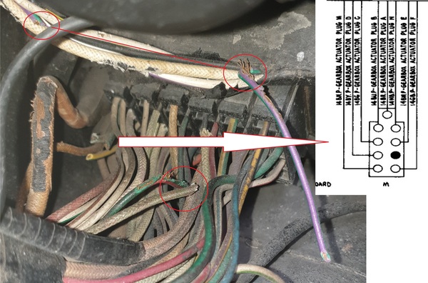 So at this early stage, does anyone want to take a stab at what might be going on with and of this? | |||
ross kowalski Prolific User Username: cdfpw Post Number: 1267 Registered: 11-2015 |
Glen, Green with red stripe looks like rodents. Some of the others as well. | |||
Glen Poolen Experienced User Username: wgipps Post Number: 198 Registered: 03-2018 |
Ross - the first guy I had look at it said the same thing. Im still at a loss as to what has happened mechancially and electrically and how its working. In the 1st pic, in Plug F, all the wires have been cut, except 1 that doesnt appear on the wiring diagram. On the 2nd pic, Plug M, at least 3 wires that have some sort of control over the gearbox have been cut. I would have thought this would be causing all sorts of mechanical problems and at least a lot of electrical gremlins. Brake light switches, rear demister and windscreen wipers/washers are safety items and they are working fine. As so far as I can tell, the car is running well. There are some minor electrical gremlins currently existing (some of the dash lights flicker when i change gears) but I doubt this would be the only outcome of cutting those wires. One part of me thinks to reconnect them and see what they do but then i think if i do that it will probably cause more problems - ie they were probably cut for a reason. So what seems to be the general consensus on unknown cut wires? | |||
David Gore Moderator Username: david_gore Post Number: 3491 Registered: 04-2003 |
Glen, Be super cautious twice over - you cannot know what was done and/or happened earlier elsewhere in the system that resulted in the need to cut the wires. Just reconnecting them without tracing and checking their original destination first could have disastrous consequences if there are short circuits/failed components or more. Patience and caution will be required in abundance before you get things sorted out. | |||
Martin Taylor Experienced User Username: martin_taylor Post Number: 167 Registered: 07-2013 |
Glen, have a look at the plugs on the opposite side, these plugs and sockets often corrode (and the design was changed by the factory mid 72), one reason why you never wash a shadow engine with water. The inside plug may also be cut and the wiring bypassed directly to the end device if everything appears to be working, those plugs are an awkward reach at best so understandable if an auto electrician bypassed them somewhere (not that I would do it that way) | |||
Glen Poolen Experienced User Username: wgipps Post Number: 199 Registered: 03-2018 |
Yeah Im thinking to just let it be. This car is 1974 so it will have the bettered design you identify Martin. Im not going to look for the other sides - i dont want to create more questions. I first went looking at this stuff because of their location I thought I might be having problems with my heater/air conditioner. Then I noticed the ones on the driver side as well. So I think I can chalk this one down to 'getting to know your car' and Ill let it be. Im 99% happy that things are working as they should - in that I cant detail any specific fault in the systems identifed. However - im still happy to work on getting a hi-def scan of the original wiring diagrams for the RR community so ill make a post in the Wanted part of the forum. | |||
ross kowalski Prolific User Username: cdfpw Post Number: 1269 Registered: 11-2015 |
Glen, It looks like all the wires in that plug are supposed to be plastic coated, but they appear to be cloth coated in the picture. Are you sure that's the correct plug / diagram? | |||
ross kowalski Prolific User Username: cdfpw Post Number: 1270 Registered: 11-2015 |
Glen, The wires at the gear change selector go from a cannon plug through a wire bundle directly to the firewall plug. As Martin said someone might have rewired it to bypass things, but if you trace the wires back from the gear change servo, you will at least know what's going on. Also it's possible to lose wires to the gear change servo and still have it work. Have you tried shifting into all the gears? | |||
ross kowalski Prolific User Username: cdfpw Post Number: 1271 Registered: 11-2015 |
Glen, Complete agreement with David, absolutely no reattaching previously cut wires without first checking them out completely. I'd normally want to know what was done for a repair in a situation like this even if things seem to be working OK. People do some really I'll thought out and slapped together hack jobs in cars especially when It comes to wiring. | |||
Glen Poolen Experienced User Username: wgipps Post Number: 200 Registered: 03-2018 |
Ross -- "Are you sure that's the correct plug / diagram?" Not at all - that is just my best guess. The wiring description - toeboard, 6 sockets in a row, both left and right hand sides and the top/bottom orientation of the plug setup leads me to this conclusion. I cant get underneath the car to check on wires. Ive got a few hours work for an auto-elec on some other little bits I need done (he does a lot of RR work apparently) so my plan is now to run a few checks on these wires to see whats what. I can change into all gears although sometimes it plays up with regards to the actual gear its in compared to the location of the gear selector on the steering column. | |||
Martin Taylor Experienced User Username: martin_taylor Post Number: 168 Registered: 07-2013 |
Glen, the other side of those plugs is in the car in the foot wells, not underneath. |