| Author | Message | ||
Kelly Opfar Prolific User Username: kelly_opfar Post Number: 215 Registered: 7-2004 |
Given the recent topics discussing accumulator rebuilding, I thought I would create a post describing how it is done using the correct tools. I hope my friends here will forgive the shameless infomercial since I am using tools I make and sell and it is a service I offer. I like to split spheres outside instead of in my shop because it allows the use a long cheater bar if needed - as will be demonstrated soon. I have a post mounted on the back patio that can hold a grinder/buffer, tubing bender, anvil or in this case, my outside vise (to distinguish from my inside vise). My wife loves this. I place the fixture in the vise and hold onto it securely: 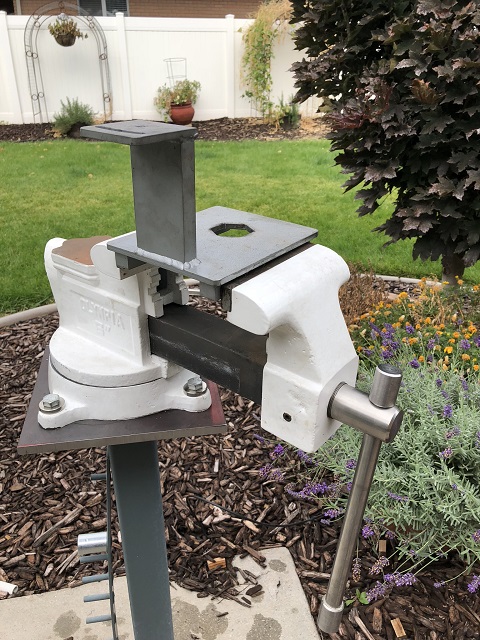 Then the accumulator is placed in the fixture. The tool I offer comes with a large nut that keeps the accumulator stable in the fixture. This is important when trying to break free a recalcitrant clamping ring. Finger tight is plenty for this nut. It�s not going anywhere. 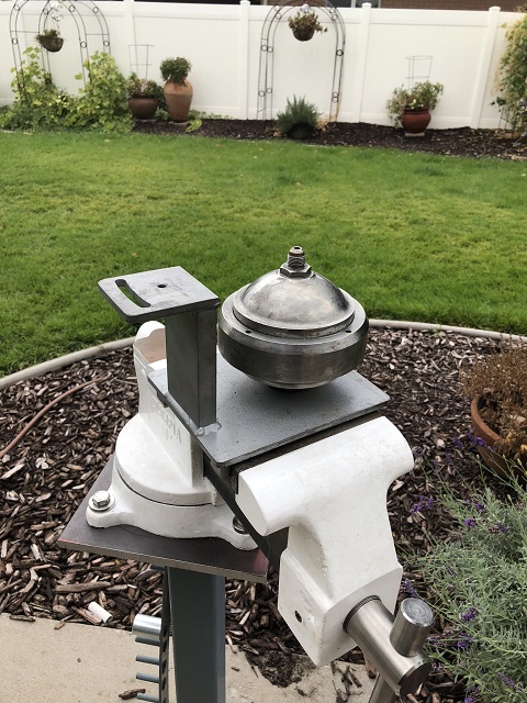 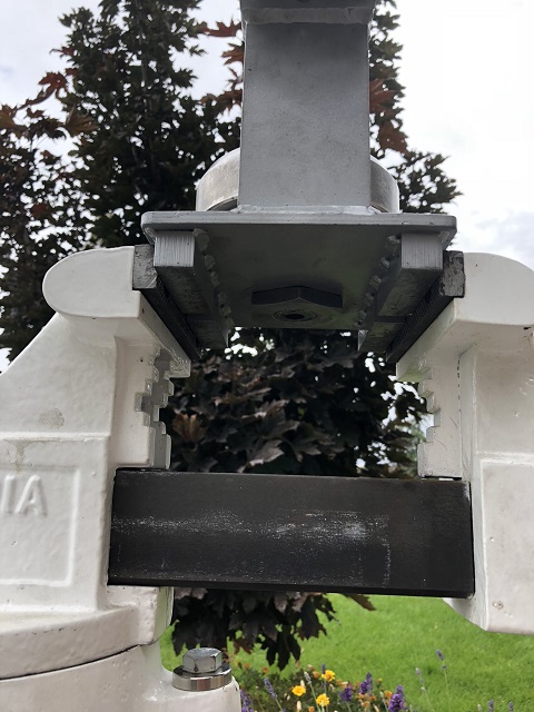 This is a good time to make sure the sphere is depressurized. I use a little tool I made that relieves the pressure gracefully by using a hex key which slowly depresses a plunger that pushes the seal off its seat and vents the nitrogen through the little hole on the side of the tool. 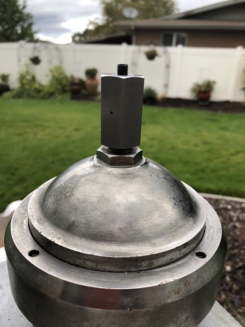 This tool is a luxury but not a necessity. You can achieve the same result with a small punch and tiny taps with a hammer. Then the locking ring socket is dropped into place making sure the pins properly engage the holes in the ring. The socket is double drilled to accommodate the two different Bolt Circles offered by The Factory. 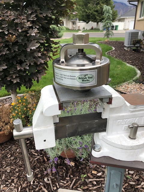 My socket features rotating tabs on the bottom that lock into place with a satisfying detent to prevent the pins from disengaging and fouling the pin holes. 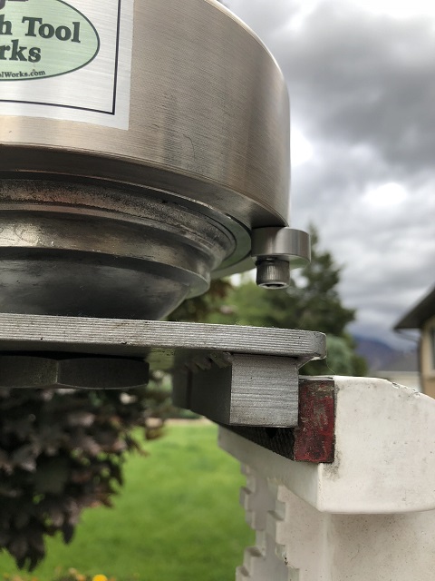 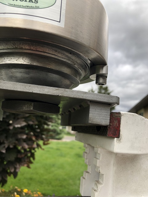 For disassembly purposes, the upper wrench is not entirely necessary, although it does hold the accumulator stable in the fixture. I can tell that this sphere was not built with the correct fixture because the wrench does not line up correctly. During assembly, the wrench is necessary to hold the two halves of the sphere relative to each other and to keep the upper half from rotating. If the upper half rotates while the locking ring is being tightened, the membrane can �smear� or be pushed out of the correct position. 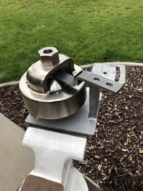 The upper wrench has a split in the center which allows for the handle portion to be rotated allowing for tall and short style spheres. This is a tall sphere shown. There is a low profile nut that keeps the upper wrench in place as well. Again, finger tight is fine. 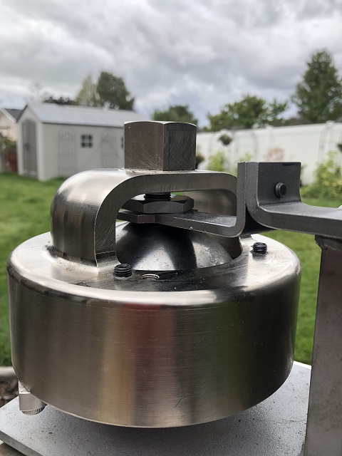 Now that everything is secured, it�s bustin� time. I have a succession of cheater bars I use starting with a 3ft. over my �� drive breaker bar. When that doesn�t work, we�ll try the 6 and then the 10-footer. Almost nothing withstands the 10-footer. Even my tiny wife can break a ring loose with a 10-footer. But more on that later. 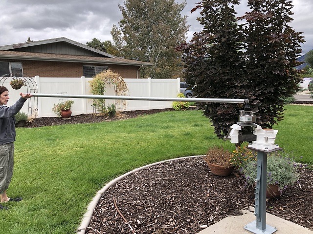 Once the ring lets go, here is what the inside looks like: 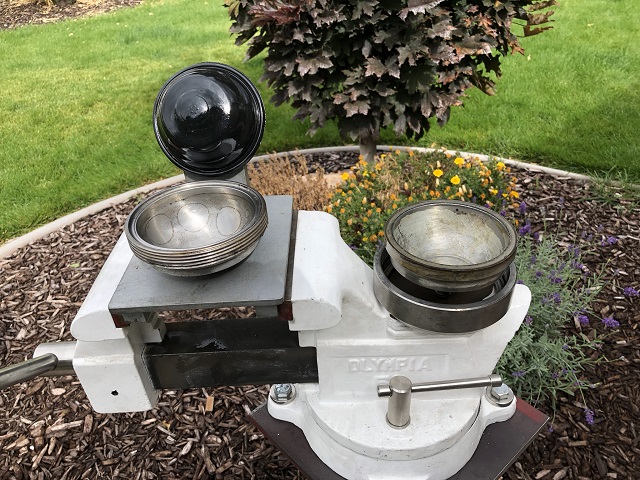 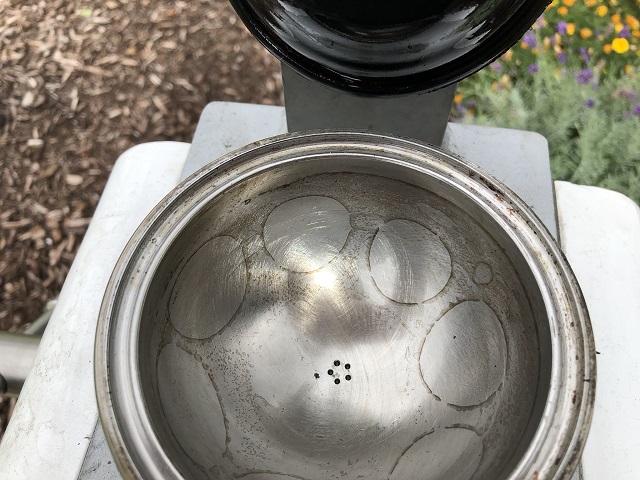 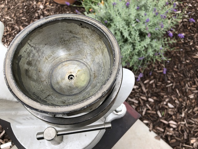 This next accumulator is not the exact one in the above pictures but it is the matching one from the same car. Whoever rebuilt this sphere apparently had a hard time. The pin holes were severely fouled: 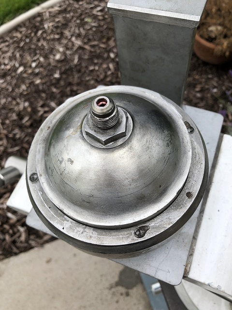 This was no problem for my fixture which locks the socket to the ring securely. We�ll repair the ring later, but first check out this membrane. This demonstrates clearly why the correct fixture is necessary. This membrane was �smeared� while being tightened by the previous builder. The builder had to know it at the time because there was no way this sphere could have charged correctly. This was probably blowing nitrogen out the fluid holes as fast as it was going in the charging port. This was apparently �good enough�. 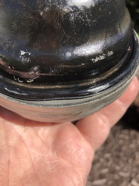 Here is the locking ring that was welded up, faced in a lathe and had the pins holes redrilled: 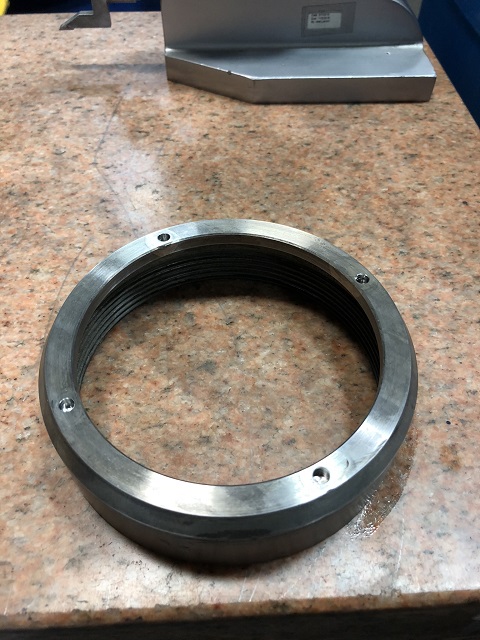 While the halves are apart, the inside of the spheres are polished in a lathe and all of the threads are cleaned up. 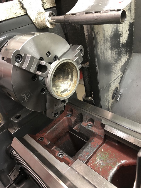 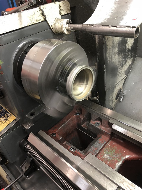 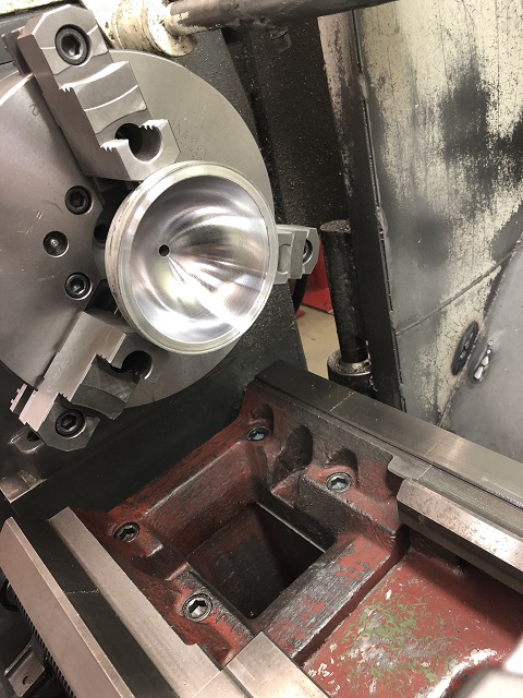 Now, through the magic of television, we show these spheres fresh back from being plated and ready to be assembled. First the charging half of the sphere is lightly clamped in the vise and the newer style of sealing bobbin from Flying Spares is inserted: 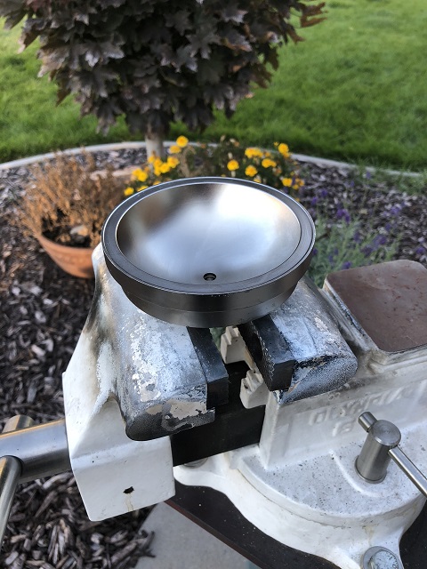 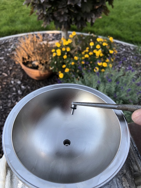 Next the spring: 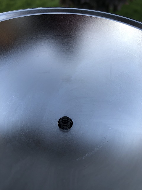 The spring cap: 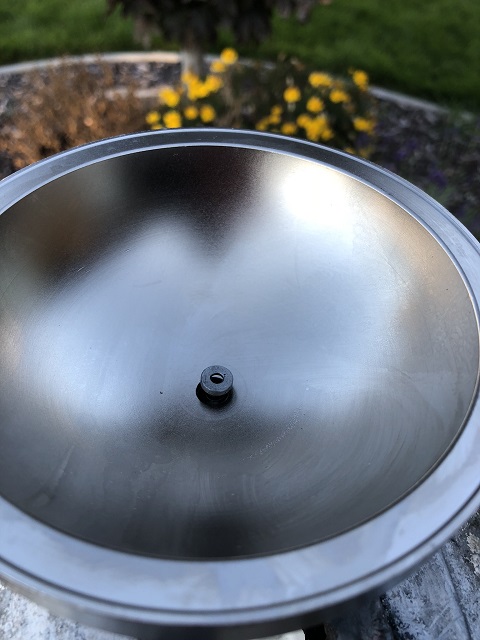 And the retaining ring: 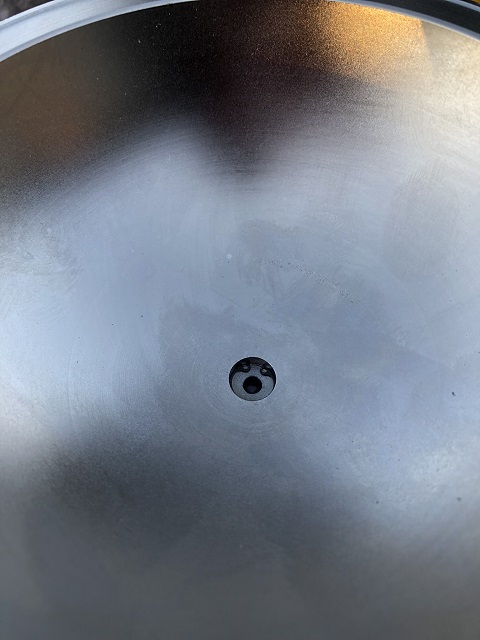 Now it is time to install the membrane. This is the upper half that screws into the accumulator control valve. I like to install the membrane positioned just like this because is displaces more oxygen when assembled and allows the charged half to have a higher ration of Nitrogen to Oxygen. 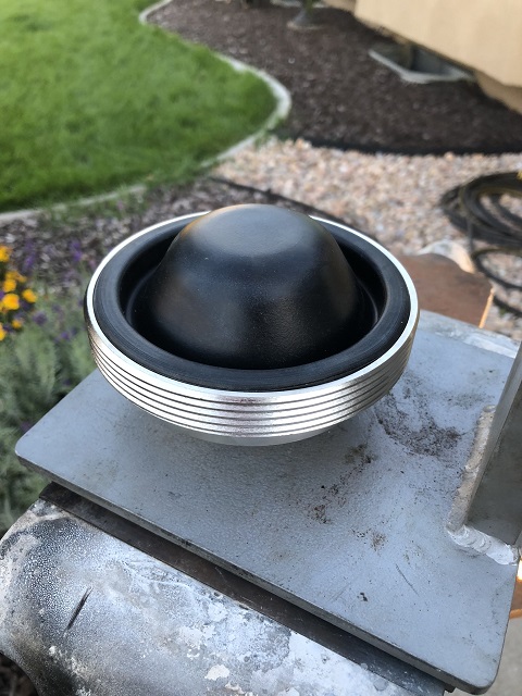 Position the charging port half in place: 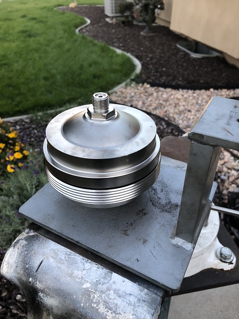 Lube the locking ring liberally with anti-seize and screw it down hand tight. Anti-seize might allow for tighter initial torque values to be applied but it will also make it easier to disassemble in the future. As an aside, I had one very rusted accumulator that took two 200lb men push/pulling on a 12ft cheater bar to break free. That wouldn�t have been necessary if anti-seize had been used. For those doing the math, that is almost 5000ft/lbs. Please use anti-seize.  Without further ado, place the accumulator assembly in the fixture, install the lower nut that secures it, install the locking ring socket, rotate the locking tabs into place and align the upper wrench with the fixture. This keeps the halves immobile relative to each other. Using your big torque wrench, tighten the socket to 275 ft/lbs. 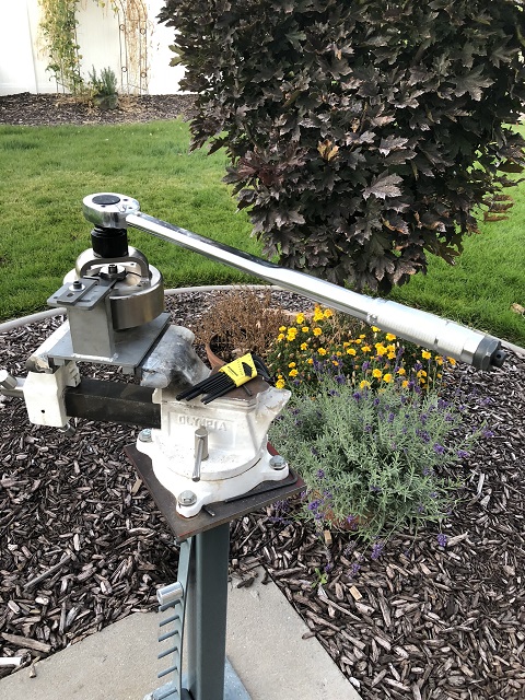 Now it�s time for charging. The first few times I charged accumulators, I had the sphere inside of a large metal cage just in case, but I ain�t skeered no more. I did this one on the lawn for better light, but I have the bottle secured to a wall in my shop now. Here is the assembly as it is charging: 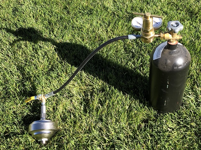 Here it is fully charged to 1000 lbs. The regulator is preset so I just have to open the valve for a couple of seconds, verify the pressure and turn it back off. 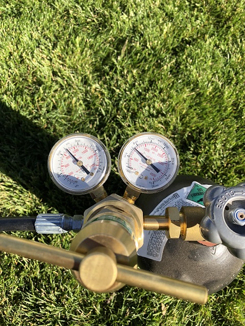 The three-way valve on the end releases the pressure in the line and the fitting can unscrew leaving the accumulator fully charged. 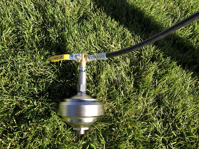 I hope this has helped those who are contemplating having their spheres renewed. I have a lovely little write-up coming soon that will detail the overhaul and testing procedure for the ACV�s. Kelly http://BritishToolWorks.com | ||
Jean-christophe Jost Frequent User Username: jc_jost Post Number: 59 Registered: 3-2016 |
Wow ! that's a Christmas post. Thank you. | ||
Paul Yorke Grand Master Username: paul_yorke Post Number: 2118 Registered: 6-2006 |
Merry Christmas . Nice indeed  | ||
Geoff Wootton Grand Master Username: dounraey Post Number: 2056 Registered: 5-2012 |
Great stuff Kelly, as always. Thanks for putting it up. | ||
Brian Vogel Grand Master Username: guyslp Post Number: 2716 Registered: 6-2009 |
Kelly, Wonderful tools and excellent documentation!! You could probably tap the end of that 10-foot extension with a tack hammer and have it break the clamping ring loose! I had not even realized that my own, far more primitive, setup included some of the features far more elegantly included in your own. I just knew I wanted something that kept a "death grip" on both halves of the sphere when removing or installing the clamping ring and that did almost the same for the clamping ring in the wrench. Poor me, sans metal lathe, I had to use fine steel wool to do what polishing out of the insides of the spheres that I could, and no plating afterward!! A very Merry Christmas to you and yours and may 2019 bring you nothing but the best! Brian P.S.: No note about how *%$#*& miserable it can be to get the whole valve back together?!! Getting that circlip back in place without the spring and seating washer flying somewhere, often a couple of times, is no fun! | ||
Kelly Opfar Prolific User Username: kelly_opfar Post Number: 217 Registered: 7-2004 |
Hey Brian, I should have given credit where credit is due. It was your post several years ago where you showed your tool with the excellent clamping ring clamp that gave me this idea. I remarked on it at the time how much I loved it. You're also right about the retaining ring for the seal. After shooting an embarrassing amount of springs across my shop, I found a much better way to do it. I don't have any open spheres in stock for demonstration purposes, but if we can pretend that I'm holding the spring retainer down in the accumulator seal hole, the trick is to use a punch to keep the seat located and the retaining ring wrapped around the punch. 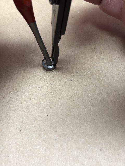 This way if the spring does what springs do, it will be captured by the punch - and you try again. Also very very helpful is to use the right pliers. I got these very tiny retaining ring pliers from McMaster.com. 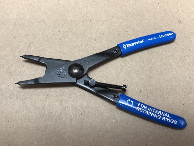 | ||
Brian Vogel Grand Master Username: guyslp Post Number: 2719 Registered: 6-2009 |
Kelly, I thought about that trick with the punch *after* having the grand struggle with both of the first two accumulators I worked on. It does work very, very well and your picture is worth a thousand words. I have two sets of spring clip pliers, both of which allow me to reverse them for internal or external spring clips. It's a miracle that one of them had pins on the end that were tiny enough for that circlip that is the spawn of Satan!! Brian | ||
Omar M. Shams Grand Master Username: omar Post Number: 1772 Registered: 4-2009 |
Wow Kelly!!! an amazing post. No wonder everyone on the forum loves you.... what a dude...... | ||
ross kowalski Grand Master Username: cdfpw Post Number: 902 Registered: 11-2015 |
Kelly, two thumbs up on having a platform on the patio so you can mount things like a grinder or a accumulator rebuild fixture. | ||
Larry Kavanagh Grand Master Username: shadow_11 Post Number: 302 Registered: 5-2016 |
Great write-up Kelly. Looking forward to the ACV testing instructions. | ||
Patrick Lockyer. Grand Master Username: pat_lockyer Post Number: 2041 Registered: 9-2004 |
Did you use the higher specification EPDM kits that are now available for the RR 363 spheres etc. Interesting info from IntroCar. https://www.introcar.co.uk/blog/2018/09/improved-epdm-rubber-seals/ | ||
Kelly Opfar Prolific User Username: kelly_opfar Post Number: 219 Registered: 7-2004 |
Nope. I prefer to use FS's kit with the genuinely improved charging port seal kit. I'm going to reserve judgement on Introcar's magic beans. |