| Author | Message | ||
ross kowalski Grand Master Username: cdfpw Post Number: 888 Registered: 11-2015 |
All the cars are asleep for the year so I figured I'd tear into the shift servo. SRH 8844 wasn't shifting into park for the last couple weeks of the RR driving season. I had pulled the servo from the car some time back and with my wife on holiday for the week I opened the box on the kitchen table. Here's the contact wheel. It's silver plated. I cleaned it with some toothpaste, and wiped it clean with some water. 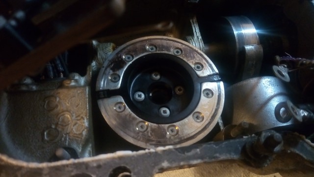 I did the same treatment on the spring contacts. 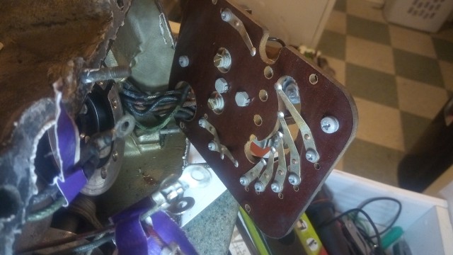 I then looked at the wiring diagram. It's nice to have an OEM factory manual which is easier on the eyes than the pdfs. And figured out what the wires do sort of. There's a couple other wires for the internal motor brake and some kind of interlock. 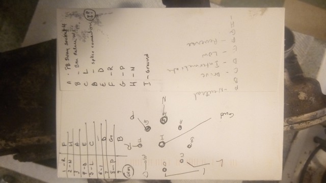 When I was under the car last time I was able to measure voltage at the appropriate pins at the chassis harness. I was able to ground the center pin and power the other pins and get it to move into all positions but park. Does anyone know of a testing procedure for this thing with it out of the car? I think it's the same one Dodge used in the USA. Which pin is the I position? The wiring diagram was a little unclear on this point. It looked like one number going into the LH M plug and another number going out. If there isn't a good how to on testing these maybe I can film one when I figure it out. | ||
ross kowalski Grand Master Username: cdfpw Post Number: 889 Registered: 11-2015 |
Oh my, I took a look at the Dodge take on push buttons and it's some sort of mousetrap with a cable. Back to the RR factory service manual or the VOM. | ||
Paul Yorke Grand Master Username: paul_yorke Post Number: 2113 Registered: 6-2006 |
Just a feed and earth to the unit. The fingers are sequential so test by giving a feed to each pin (pretty sure it's a feed not an earth. Make sure you lubricate the contacts. You can make the unit go through 360 degrees so make sure the arm ends up facing towards the ground when finished. If it was functioning except for one gear I would look at either one finger or connection being poor or the wire to the park position being damages, possibly at the plug into the actuator. Good luck with her. | ||
gordon le feuvre Prolific User Username: triumph Post Number: 282 Registered: 7-2012 |
Ross, please don't forget to remove the column cowl and clean the contact points for the selector lever. all will be apparent when column cowl removed!! | ||
Patrick Lockyer. Grand Master Username: pat_lockyer Post Number: 2020 Registered: 9-2004 |
The column selector contacts were cleverly repaired by Ross I seem to remember. | ||
ross kowalski Grand Master Username: cdfpw Post Number: 903 Registered: 11-2015 |
Mystery solved... SRH 8844 had lost park just before the end of the local driving season. I had done some diagnosis but forgot what I did so I started again. So here's what I did and some interesting info for those who might be in the same boat. I cleaned and tested the shifting servo which really ought to be a thread itself as that is a little tricky to do. Not so bad once you understand what all the pins do! I will upload a dxf cd file for cutting a shifting servo cover and a wiring diagram of the shifter connections. With a known good shifter servo, I tried all the shift positions and sure enough park didn't work. I checked at the connector from the chassis harness to the shifter and each pin did what it should when in each position of the gear switch. Working servo, correct voltages on the pins at the connector, but no shifting into park... Now that's odd.. I had been doing this diagnosis work using a meter to read the voltages because it happened to be sitting on the table. Anyhoo, I pulled out the real test light and tried again. Sure enough the wire on park lit, but it was dim. I pulled the connector at the bulkhead ("M" connector by the way) and checked there, bright light = problem with the harness to the shift servo. Turns out you could read 12v on the connection but when there was a load on it, no real current could pass. Nice thing about analog test lights. I opened the connector and sure enough the park terminal was corroded. 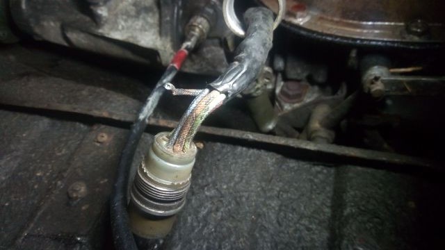 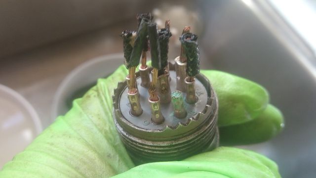 Here is information about the connector for anyone in a similar situation. 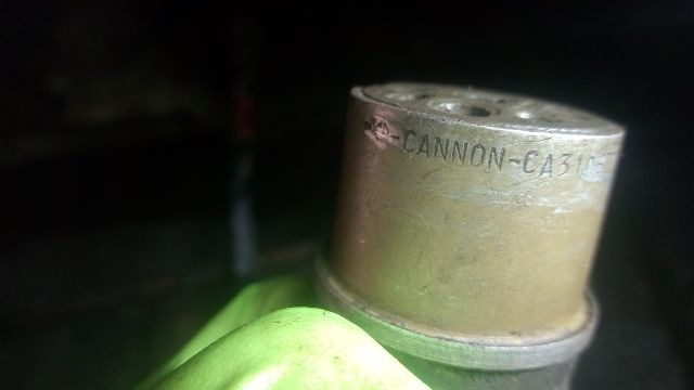 The connector is an ITT CANNON CA3106E20-16S - f80. The model # is decoded as follows. CA - ITT Cannon designation 3106 - Straight plug E - Resilient insulator and integral clamp for cable strain relief 20 - shell size 16s - pin arrangement (20-16 is 7 small pins and 2 larger ones) F80 - Snap-in crimp contacts If one wanted to just order new silver plated terminal pins for the connector they are as follows 031-8555-110 for the 7 small ones and 031-8557-000 for the 2 larger ones. I priced out the replacement terminal pins and found that purchasing a whole new terminal with pins from Ebay was the same price. The terminal is available new from Mouser or Digikey, but costs $75 USD. | ||
Robert J. Sprauer Frequent User Username: wraithman Post Number: 95 Registered: 11-2017 |
On later cars there is no connector and it is hardwired | ||
ross kowalski Grand Master Username: cdfpw Post Number: 904 Registered: 11-2015 |
Robert, That might have prevented the corrosion I experienced here if they did use plastic insulated wire rather than cloth. | ||
ross kowalski Grand Master Username: cdfpw Post Number: 905 Registered: 11-2015 |
Here's a link to the files Including the wiring diagram. I think they're right but if not, let me know. | ||
ross kowalski Grand Master Username: cdfpw Post Number: 906 Registered: 11-2015 |
Paul, Good call on the crusty connector. Could you use a replacement cannon connector or two? | ||
Steve Emmott Experienced User Username: steve_e Post Number: 32 Registered: 11-2018 |
Ross some good information and you are actually hi-liting a quite common problem which should not be overlooked when searching for electrical faults. Never rely on a simple test meter when looking for a disfuntioning component always use a test light which will simulate a load. Resistance like a corroded connector can still show the voltage as you state but will not allow current to flow to the load. Pictures show a bench test to prove the point 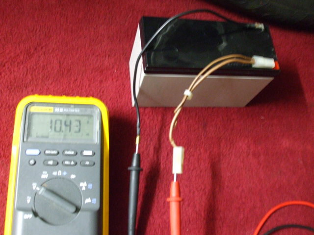 First picture shows the battery voltage 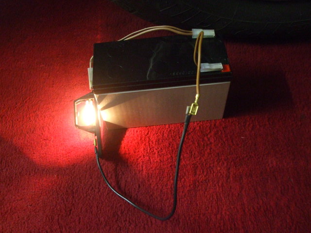 Second picture shows the battery powering the light 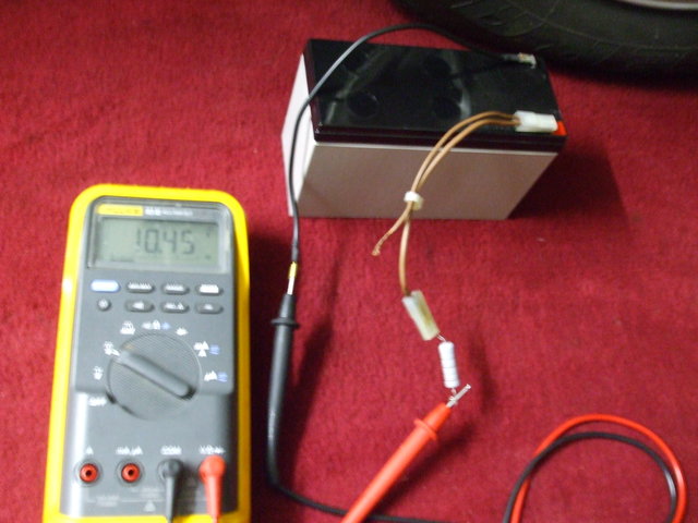 Third picture simulates a resistance in the circuit but note how the test meter still shows the battery voltage 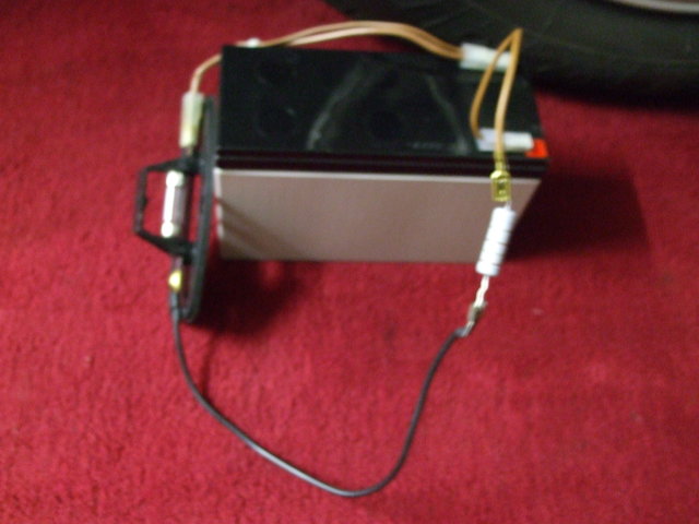 Fourth picture shows how despite a voltage being seen at the end of the resistor when the load is connected the light does not work. Obviously depending on the value of the in line reistance sometimes a component might function partially like a motor running slower or a dimmer light produced but in all cases the voltage will show on a test meter appearing correct | ||
Paul Yorke Grand Master Username: paul_yorke Post Number: 2124 Registered: 6-2006 |
Hi Ross, glad you found the problem. This was quite a big problem back in the 70s and I changed quite a few looms at the time. Testing with a load is important. These new LED test lights are pretty bad at testing this as you can imagine. Later cars do not have the cannon connector. Better or worse? Take a look at these pics . . . https://m.facebook.com/story.php?story_fbid=2029722683730560&id=137933226242858 | ||
ross kowalski Grand Master Username: cdfpw Post Number: 907 Registered: 11-2015 |
Paul, I guess I'll stick with the connector I think. Also, I wasn't joking about the connector I got a good price on a lot of the things. Now I have extra. | ||
Paul Yorke Grand Master Username: paul_yorke Post Number: 2126 Registered: 6-2006 |
Ross, for sure mate. I'd heard about the connectors and seen part numbers etc but TBH I've not had that fault for many years. Great work getting and sharing the info though. I remember digging sockets full of silicone out trying to get to a solderable point. Cheers. } | ||
ross kowalski Grand Master Username: cdfpw Post Number: 908 Registered: 11-2015 |
Look what santa brought... 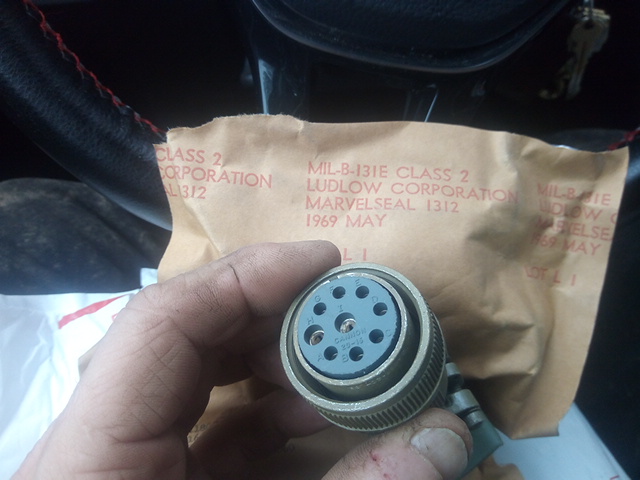 I'd install the connector, but despite being 50F it's pouring rain and I'd like the splice area to begin it's life dry at least. 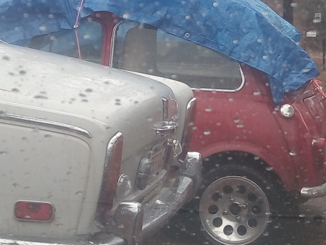 | ||
ross kowalski Grand Master Username: cdfpw Post Number: 909 Registered: 11-2015 |
Apparently at least some version of this connector had a little o-ring. 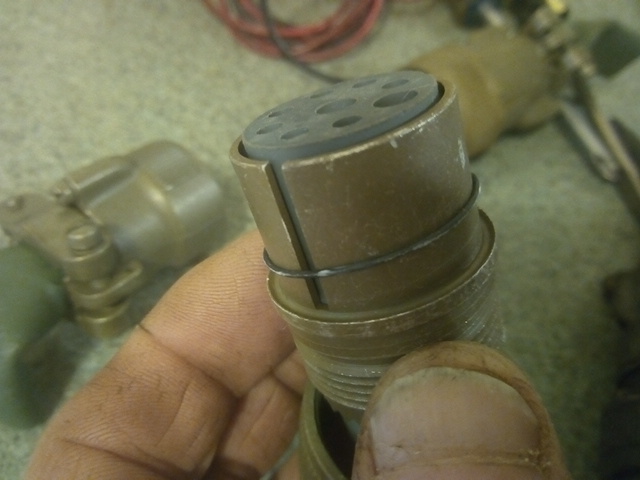 It makes sense but I just noticed the safety wire holes. 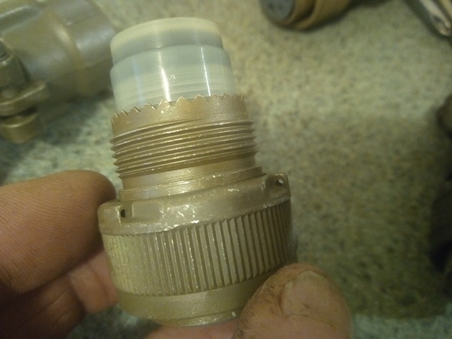 The terminals are the solder style rather than the crimp style. I am far happier with soldered connections. 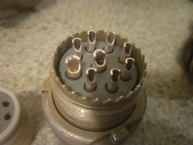 There are two screws adjacent to the clamp straps. No idea what they are for. 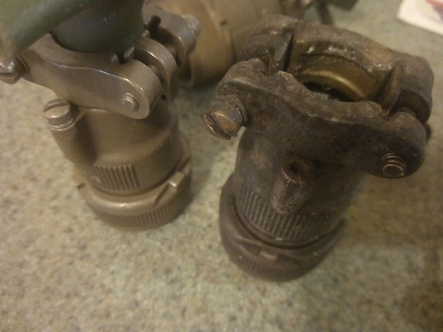 | ||
ross kowalski Grand Master Username: cdfpw Post Number: 910 Registered: 11-2015 |
Fits like a glove. I did chase the threads on the gear change servo with the original connector using a cleaning mixture of 50% paraffin and 50% sewing machine oil. There was probably some dirt in there to act as an abrasive as well. 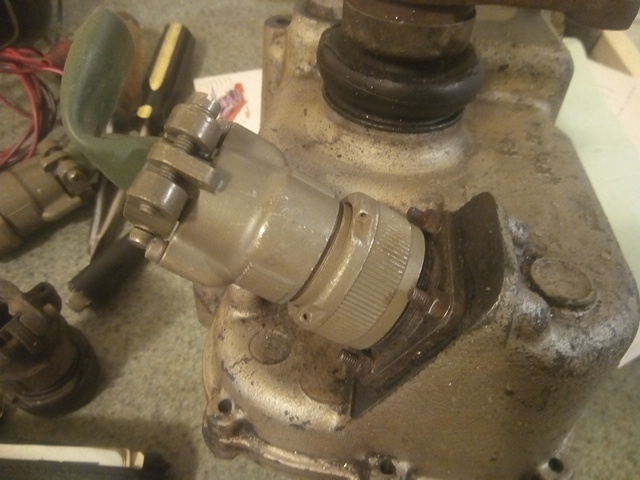 Anyone know if FS has a replacement boot for the arm. Mine is five kinds of perished and this would be the time to fit another. 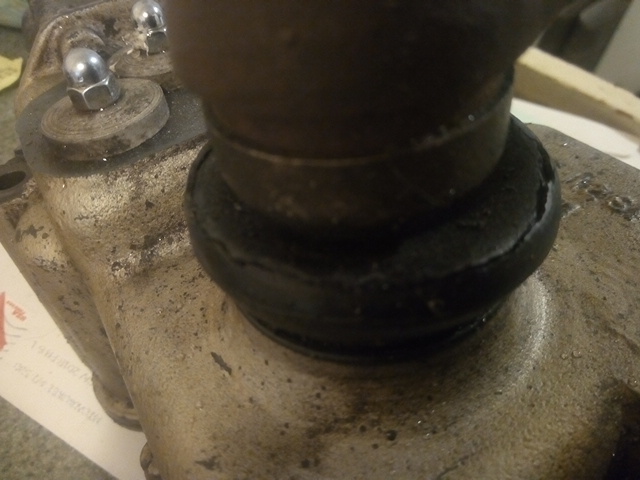 | ||
ross kowalski Grand Master Username: cdfpw Post Number: 911 Registered: 11-2015 |
Also, you might have noticed there are a lot of pictures. I just figured out that the VGA resolution of the stock android OS camera is 640 x 480 which means one can take forum ready pics without resizing. Not that I particularly like typing on a phone, but the picture part is pretty slick. You write something, click upload then one option is camera, which brings you to your camera which you use to take your picture. I looks like I won't be resizing pictures anymore. | ||
Paul Yorke Grand Master Username: paul_yorke Post Number: 2127 Registered: 6-2006 |
Nice work Ross. I don't know why but I feel that there were blanking caps that are retained on a strap which may have gone to one of the screws. Not for RR&B but for aviation or military applications. I'll probably have a good boot here if you can't find a new one. Cheers,Paul. | ||
Kelly Opfar Prolific User Username: kelly_opfar Post Number: 218 Registered: 7-2004 |
The gaiter part number is UR11240. FS and Introcar both say out of stock. You could enquire. | ||
ross kowalski Grand Master Username: cdfpw Post Number: 912 Registered: 11-2015 |
Paul, I'll probably try and find one. I measured it and it was 40 mm for the base, 16mm for the shaft and 17mm for the height. I suspect it is the same as some sort of 60's or 70's ball joint or something. I have to think it is metric because the 40mm and 16mm were exact measurements. Soo.... Off to some research. Kelly, good start to the research. | ||
ross kowalski Grand Master Username: cdfpw Post Number: 913 Registered: 11-2015 |
this? | ||
Paul Yorke Grand Master Username: paul_yorke Post Number: 2129 Registered: 6-2006 |
Looks worth a try  | ||
Steve Emmott Experienced User Username: steve_e Post Number: 36 Registered: 11-2018 |
If you can't find a suitable standard ball joint rubber then this company has them as a patterned part and a lot of other usually hard to find parts. Not sure of price and service quality......never liked anyone that does not show their prices but at least on your side of the pond.... http://www.albersrollsbentley.com/home/hard-to-find-parts/ | ||
ross kowalski Grand Master Username: cdfpw Post Number: 914 Registered: 11-2015 |
Success. I soldered the terminal on this morning. 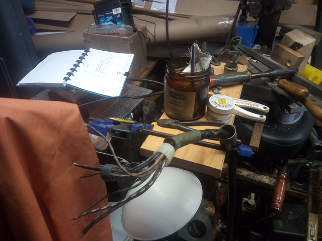 The quality was good considering the soldering iron I was using. 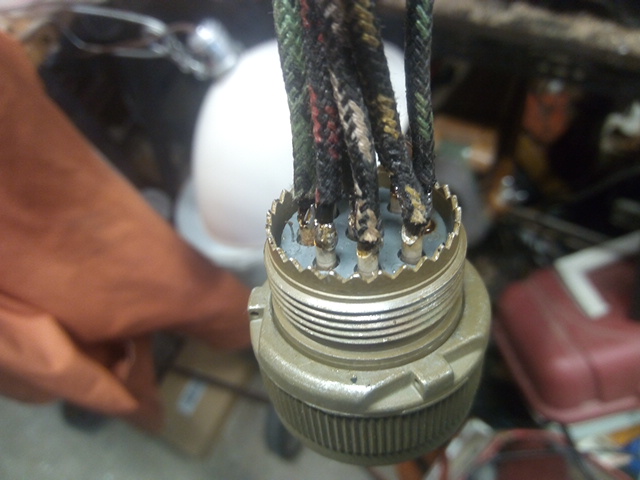 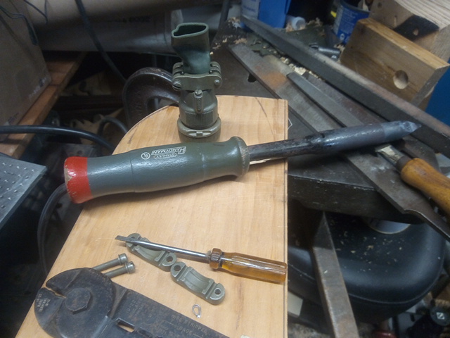 I lubed up the holes and rubber collar with lanolin. 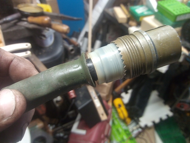  You have to hold the wire bundle at the back and barrel at the front while you tighten the back seal so it pulles in without twisting the wires. 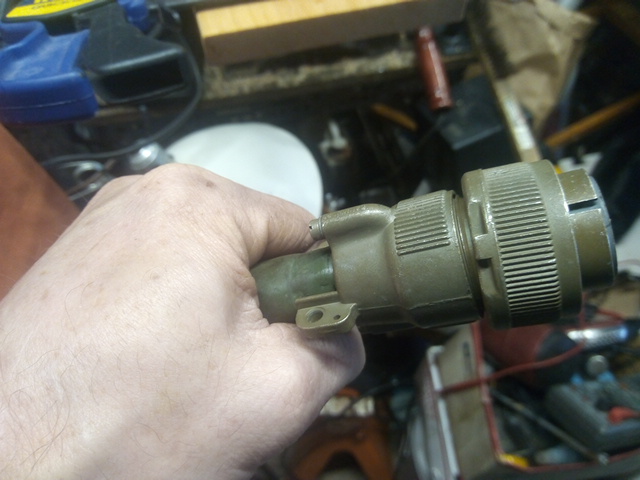 | ||
ross kowalski Grand Master Username: cdfpw Post Number: 915 Registered: 11-2015 |
All done up nice and tested. 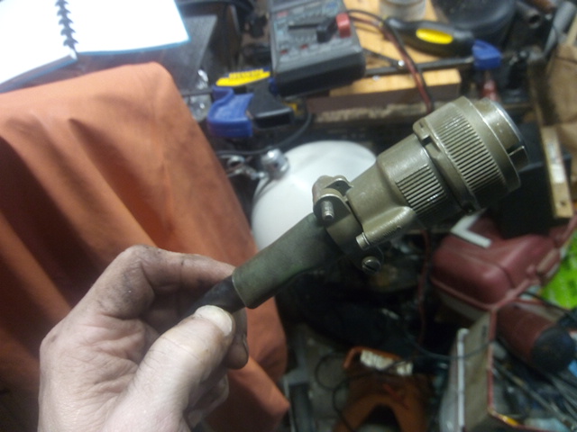 Here's a shot of it being tested before installing it. a video clip of gear change servo running through the gears | ||
Robert J. Sprauer Frequent User Username: wraithman Post Number: 96 Registered: 11-2017 |
May I suggest a soldering station. They are the best for circuitry and applications like this. What you have there is bulky and best suited for stained glass work. The soldering tips on the stations use smaller tips and slender handles and are very comfortable and come up to heat (adjustable) very quickly. I use Weller here. | ||
Mark Herbstreit Prolific User Username: mark_herbstreit Post Number: 194 Registered: 5-2005 |
UR11240 is available in Melbourne Ross. PM sent 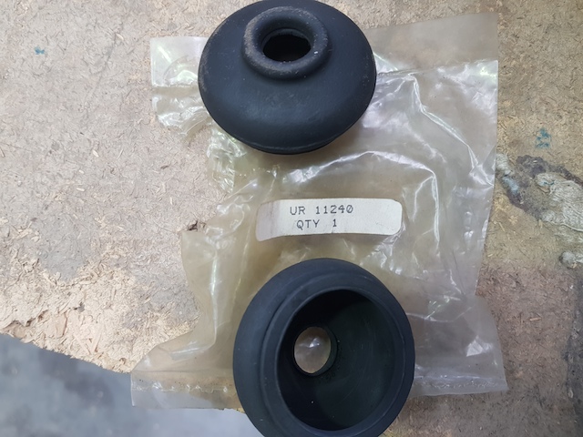 | ||
ross kowalski Grand Master Username: cdfpw Post Number: 916 Registered: 11-2015 |
I forgot a couple things. First, I didn't use the gasket I made. I used a Permatex product on the recommendation of a friend.  It sets when in contact with metal and sealed from air. What I read supports his experience with the product. I've only ever used this on volvo cam/valve cover mating surfaces but I figured I'd try it for the gear shift actuator cover plate. We'll see. I also think the best way to fit the terminal is to cut back the cloth covering 2 inches back from each pin. That way the rubber back seal on the cannon connector can bear against rubber. It's quite a robust connection, but I bet water gets in wicking through the cloth. I lubed up the cloth quite good but I bet the righter move is to carefully remove some of the cloth. | ||
Robert J. Sprauer Frequent User Username: wraithman Post Number: 97 Registered: 11-2017 |
Use dielectric grease on the pins and you will have no corrosion problems going forward | ||
ross kowalski Grand Master Username: cdfpw Post Number: 917 Registered: 11-2015 |
Robert, You are absolutely right. Probably the real pro move us strip back the insulation then FILL the solder terminal area with real dielectric grease. Some would squish out but you just wipe it down. I did spray the pins with white lithium grease but mostly because I had the can out using it on the internal contacts of the shift mechanism. In retrospect I probably would have been better off with silicone grease on those as well. Full disclosure, I have a big tube of dielectric somewhere for plug wires, but the white lithium was sitting right out so .... | ||
Robert J. Sprauer Frequent User Username: wraithman Post Number: 98 Registered: 11-2017 |
Nice work...looks good and hope everything works out for you! | ||
ross kowalski Prolific User Username: cdfpw Post Number: 1450 Registered: 11-2015 |
Vlad, I just efited this so it would move to the top of the list. |