| Author | Message | ||
Alan Scard Experienced User Username: alanscard Post Number: 31 Registered: 7-2015 |
Ref. 1972 Shadow SRH 13952 The insulation on my stove pipes was either falling off or non-existing, so I thought I would remake them. Using standard brake pipe with new hardware was easy enough. The 4 brake nuts are UNF 3/8� x 24 tpi short female for 3/16� pipe. The union adaptor that goes into the exhaust manifold hot air tube is a brake tube connector 3/8� x 24 tpi male. The existing union adaptor in my butterfly housing has a short thread so I had to add a small, about 1/8� long, spacer between the nut and the flared-out choke pipe. The adaptor thread on the thermostat was long enough to except the new nut. I used 1� wide heat wrap ceramic fibre exhaust manifold tape around the brake pipe, with tie wraps at each end. I tried stainless steel tie wraps but would not grip on such a small diameter pipe. I then covered the insulated pipe with 12mm internal bore heat resistant 500-degree C black high temperature fibre braided cable sleeving. All parts were sourced from EBay at minimum cost. Hope this helps other people. Alan in the UK 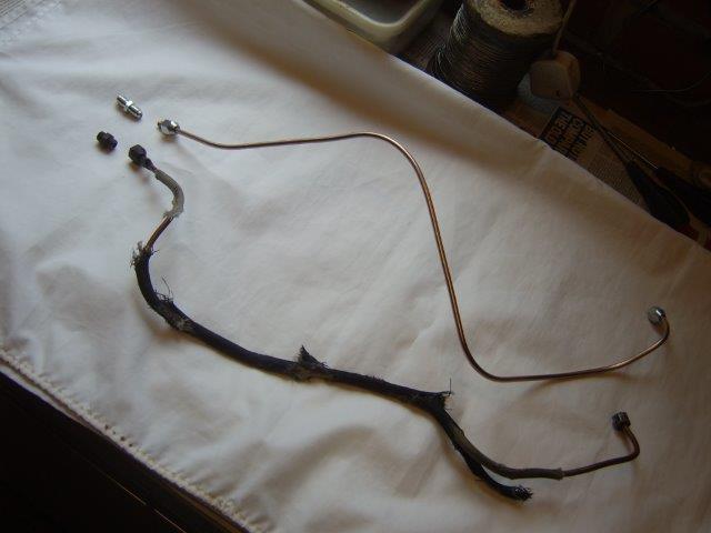 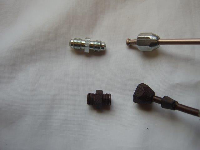 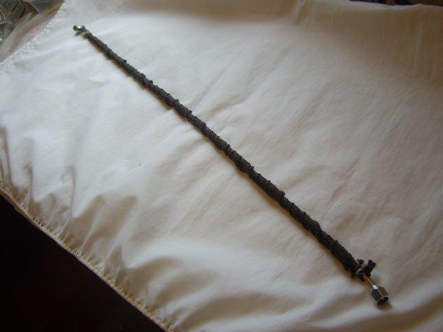 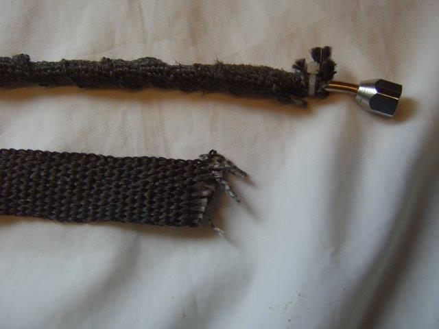  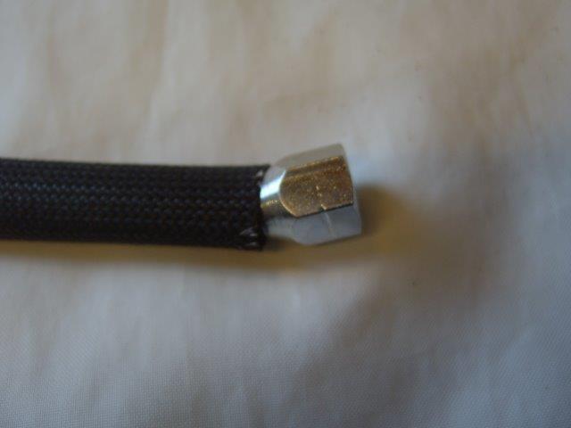 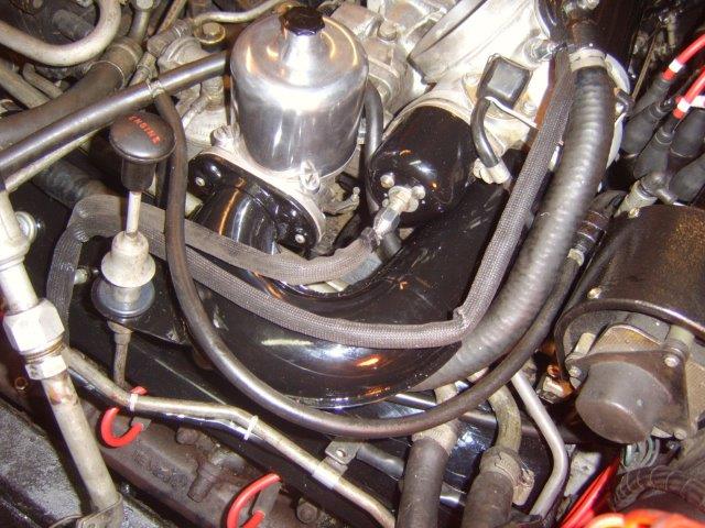 . | ||
Mark Aldridge Grand Master Username: mark_aldridge Post Number: 582 Registered: 10-2008 |
I remade my stove pipes out of 6mm copper tube, and bored out the tops of the threaded fittings accordingly. This appeared to be nearer the original ID. Mark | ||
Jean-christophe Jost Frequent User Username: jc_jost Post Number: 56 Registered: 3-2016 |
It does help me thank you. Beautiful engine. | ||
Steve Emmott Experienced User Username: steve_e Post Number: 12 Registered: 11-2018 |
I never really understood why the pipes were not made of copper in the first place. It would have been such a small on-cost given the selling price of these cars which were well engineered....albeit indeed in places well over-engineered anyway. Putting the cosmetics aside these pipes are critical to the performance of the automatic choke function and whilst the insulation can deteriorate so does the original metal pipe simply rot/rust perforate. To function properly for the automatic choke operation the piping and connections from the carb down to the exhaust manifold and then to the automatic choke mechanism need to be totally airtight. So many times I have seen mixture settings messed around with by garages when the problems are simply this piping and also the pipe inside the manifold which is not visible but equally can rust through and becomes perforated. Tell tale signs here are black soot appearance inside the choke where the metal coil is. For the automatic choke to work air is drawn through the tube and passes over the choke coil. As the air gets warm passing through the exhaust manifold tube it heats up the metal coil which slowly causes the metal coil to expand and fully opens the carb butterfly. Removing the large rubber air induction pipe from the top of the carb exposes the butterfly and it is easy to see if this quickly fully opens as the engine warms up. If its operation appears very slow to open up fully then suspect some air leaks first in the tubing. Whilst the tubes are disconnected it is worthy of doing a vacuum/pressure/leak test from one end of the pipe run to the other. Just seal off one end to check or a simple quick DIY test is to strap a party baloon on one end and 'lick your lips' and see if you can blow the baloon up from the other end.  Or if concerned on health and safety use a bicycle pump. Or if concerned on health and safety use a bicycle pump. If the piping leaks anywhere you need to check it all out including the manifold attachment which is just a small 'u' shaped metal tube same as rest of original piping. This one however needs to be replaced with metal tubing and gas/mig welded in place. Pipes then do need to be well insulated as Alan has done. This is not really for touch safety but ensures the hot air performance to the choke mechanism is maximised. There are a few other parts that can affect general choke operation from the choke solenoid to the cincilla time delay device hidden under the area where the relays and relay board are by the blower motor in the engine compartment. When all set up correctly I have seen fuel performances nearly double in MPG. | ||
Michael Carr Frequent User Username: carsie Post Number: 56 Registered: 7-2016 |
Useful explanation - Thank you Steve  |