| Author | Message | ||
leonard stampton Experienced User Username: 1000leonard Post Number: 12 Registered: 3-2018 |
I would like to re gas the No 2 accumulator on my Shadow 2, SRH 31710 an Australian delivery and currently domiciled in Melbourne. I have a copy of a very interesting article written by Jean-Michel de Ripert de Saint Martin which includes notes by Brian Vogel. Has any forum member out there successfully tried the method described? No 2 accumulator is generally assumed to be impossible to service in situ. Jean Michel suggests the accumulator could be unscrewed from its control valve and then removed from the car. I would be grateful for any responses and especially for information where the necessary equipment might be had...��...Regards | ||
Robert J. Sprauer Experienced User Username: wraithman Post Number: 46 Registered: 11-2017 |
British Tool Works has the tools you need. Even with the tools one must have experience with the process. Nitrogen sourced gas and a cage when filling to avoid explosion. The investment in tools and risk is not worth the cost and exchange is the most practical choice. The internal diaphragm also gets replaced and must not be distorted when the sphere is tightened. | ||
Christopher Williams New User Username: christopher_williams Post Number: 9 Registered: 5-2017 |
I rebuilt mine last year, and I'll never do them again. As Robert states, for the investment in tools, the rebuild kit, the pieces needed to recharge them, it just isn't worth it. I've now switched to the disposable spheres designed for the SY variants that are available at Flying Spares for my client's cars, and when mine go again, I'll do the same. | ||
Brian Vogel Grand Master Username: guyslp Post Number: 2601 Registered: 6-2009 |
I've rebuilt three so far and it is a PITA, that's for sure. Based on what I've found during those rebuilds I would say that none of them was necessary. The diaphragms in all were essentially perfect, and I know that hey had been in service for a very long time. The design on the charge port of the accumulators as far as using a ball bearing as the primary valve mechanism was just p*ss-poor design. The modified valve mechanism in the Flying Spares accumulator rebuild kit, which looks like an ever-so-tiny nail with no point with a very small O-ring on it, where the long part of the "nail" serves to keep the O-ring correctly positioned for sealing by serving as a guide into the charge port itself, is vastly superior. I have also taken to ditching the plastic ball that is supposed to serve as a secondary seal, retaining the O-ring in the charge port cap that is the tertiary, and using hydraulic/pneumatic thread sealant (which is removable if one needs to get the cap off again) instead. See Vixen Hydraulic-Pneumatic Thread Sealant for one example. MRO Solution 34, Loctite 545, Permatex 54540, and VibraTite 440 are others. Since we're talking low pressures (yes, 3000 PSI in the world of hydraulics is relatively low) I'm more than happy with the stuff that is rated for 5000 PSI. The "big names" are far more expensive and are overkill in our application. It is far more effective at preventing the escape of any nitrogen that's trying to get out via the charge port. In my case, the cost was easily worth the effort. Getting the pin wrench made along with the setup to hold the accumulator in a vice was less than it would have cost me to have one rebuilt. This is not a task for the easily discouraged, I will say that. Getting one of those accumulators open required giving it some significant whacks around the retaining ring while holding it on a concrete floor in order to release its death grip. The others were just a lot of grunting at the end of a very long lever with a couple of swift thwacks on the end of it to get the ring to break loose. This is, of course, after depressurizing the accumulator entirely before starting. We don't want "an uncontrolled separation." By the way, I don't know of anyone who actually uses a cage when recharging these things, and that includes the aircraft mechanic whose a friend of mine who recharged mine as a favor. Brian | ||
Geoff Wootton Grand Master Username: dounraey Post Number: 2005 Registered: 5-2012 |
I rebuilt mine about 5 years ago. They are still holding really good pressure. If I need to recon them in the future I will probably do them myself as I have kept the tools I made to separate them. However, if I was starting from scratch I would buy reconditioned units as I now know Jim Walters supplies them to Canada/US. When I rebuilt mine I only knew of Flying Spares and the problem for me, being in the US, was the shipping costs from the UK. These are doubled as the originals have to be shipped on an exchange basis. If I lived in the UK then definitely it's a no-brainer - drive down to Flying Spares with your old units and buy two reconditioned ones over the counter. The people who recharged my units didn't use a cage either. The thing is, the spheres are pressure tested to 3000 psi every time you drive the car, so taking them off and recharging at 1000 psi seems to me a safe thing to do. Here's a tip for anyone reconditioning the ACVs, a job that is typically carried out with the spheres - make sure you replace the aluminum sealing discs. They are available at British Tool Works. I had a really elusive leak on my ACV which I eventually tracked down to a hardened sealing ring. | ||
Geoff Wootton Grand Master Username: dounraey Post Number: 2006 Registered: 5-2012 |
Leonard - I have not read or know of anyone unscrewing the sphere with the acv in-situ, although I recall a discussion on the subject a while ago. I guess the danger would be an explosive decompression if the outer sealing ring was shifted by mistake. As long as the sphere was depressurized first it would be safe. I would be very interested to see the article, if you could post a link to it. | ||
Brian Vogel Grand Master Username: guyslp Post Number: 2602 Registered: 6-2009 |
Geoff, I believe Bob_UK/RNR has done so and we had a discussion on these very forums about same. He also cited a part of the Workshop Manual that talks about unscrewing the accumulator (as in the whole accumulator) from the ACV using a socket on the hex that surrounds the charge port. One must, of course, remove the charge port cap to do so (or at least one does on the SY2 cars, as there is not space enough for a deep socket otherwise). I cannot for the life of me come up with the correct combination of search terms to pull it up at the moment. I recall there being some passing statement to watch to make sure that the two halves of the accumulator were not beginning to move independently of each other, but based on my experiences getting these things apart I'd say the probability of that ever occurring is about the same as my becoming an Olympic class athlete - as close to zero as conceivably possible. If you ever had the two halves anywhere near to loose enough at the central ring to allow them to move independently of each other the accumulator would depressurize very quickly. Brian | ||
leonard stampton Experienced User Username: 1000leonard Post Number: 13 Registered: 3-2018 |
Many thanks for the replies. Geoff, I cannot for the life of me remember where I got the article from on the internet. However if you send me your email address I will scan it and send it on to you. Briefly Jean Paul describes using a paint ball cylinder that was supplied with an integral 1000psi regulator. He connected this to each accumulator in turn and charged them to 100psi as per handbook. To seal the charging cap he now relies on the fitted o ring and good quality hydraulic thread sealant, I assume along the lines of that suggested by Brian above. I note that the magority of respondents do not think that DIY accumulator recharging is really worth the candle ! However I enjoy the challenge of these close to impossible tasks,especially when they are sucessful and over ! Regards... | ||
leonard stampton Experienced User Username: 1000leonard Post Number: 14 Registered: 3-2018 |
PS the 100psi figure should of course read 1000psi.. | ||
Alan Dibley Prolific User Username: alsdibley Post Number: 158 Registered: 10-2009 |
The chance of the two halves of the accumulators unscrewing "accidentally" are minute. If there is any significant gas pressure the force on those large-diameter threads make it practically impossible to unscrew them. As a long-time Citroen nut, I know that attempting to unscrew a Cit sphere with any pressure left in the system is impractical, and the Cit thread diameter is less than the RR smaller thread so the torque resistance on the RR outer thread is HUGE. PS: The Citroen rule is "Do the spheres up finger-tight (don't spin them down)". The pressure of the oil locks them in place. If there is a leak the O-ring or sealing surfaces are damaged/dirty. Don't tighten the sphere to stop leaks - it won't work until there is a metal-to-metal seal. Alan D. Citroen CX25GTi 1988 (the last of about 20 oleo-pneumatic Cits including ID/DS GS GSA and CX) Citroen 2CV6 Charleston 1988 Bentley T 1971 | ||
Brian Vogel Grand Master Username: guyslp Post Number: 2604 Registered: 6-2009 |
Alan, Just FYI, the official torque tightening figure for the RR accumulator to the ACV is a mere 55-60 ft-lb, just a hair more than the lug nuts, which while a bit more than your description is not all that terribly much more. These things routinely get grossly overtightened by the uninitiated. The O-ring, as you say, is what's supposed to do the sealing. For anyone who's ever used a torque wrench to tighten up the lug nuts you have a very good sense of about how tight the accumulator to accumulator control valve connection should be. Given that one should very easily be able to release a lug nut, and given the torque tightening figure of 265-275 ft-lb for the accumulator clamping ring, one can see that the probability of the two halves of the accumulator ever being affected by using the bottom hex fitting to unscrew it from the ACV is approaching zero. It should also be incredibly easy to unscrew it from the ACV while that is in situ if it hasn't been grossly overtightened when put on to the ACV in the first place. This is all the more true on accumulators assembled decades ago before the advent of the use of anti-seize (which I always use when putting them back together). It's often hellishly difficult to get them apart even when you want to get them apart and that's after the nitrogen charge has been intentionally released. When I had both off of the car at the same time I would gently spin the ACV on to the accumulator until it stopped, then use a hammer to give a very light tap to the ACV to nip things down. I've never had a leak at that connection except once, when it appears that the O-ring I used was either a bad one or one made of the wrong material packaged along with a bunch of EPDM rings. Brian | ||
Geoff Wootton Grand Master Username: dounraey Post Number: 2007 Registered: 5-2012 |
Leonard - thanks for your offer but I now realize I have seen this article. I misread your first entry and thought it was specifically addressing the procedure for unscrewing the sphere in-situ. Brian/Alan The warning for accidentally separating the two hemispheres is given on page G25 of the SY1 workshop manual. However, I fully accept your assertions that the chances of this happening are virtually zero. In fact your comments have now persuaded me to try removing the spheres in situ when the occasion next arises. Leonard - I like and agree with your comment about rising to the challenge. The hard part is separating the two halves of the sphere which can become almost welded together. Here's what Bill Coburn, Author of Tee-one topics (issue 30, page 428) had to say about it: "These muthas�s are tight. I remember carrying out the undoing bit on a set of accumulators at my old matrimonial address and after using a 3/4'� break bar with a five foot steel extension and two 170K helpers, I found next day that my residence had actually changed its post code! Here's a link to a thread which contains information and pics which you may find useful. The clamp and pin wrench that I made are much less professional than Brian's, but it does show the equipment can be made cheaply and without access to machine tools. http://au.rrforums.net/forum/messages/17001/12247.html?1376347008 | ||
Brian Vogel Grand Master Username: guyslp Post Number: 2606 Registered: 6-2009 |
Geoff, The workshop manual also gives the warnings about the use of "extreme protection measures" when it comes to charging the accumulators, too. I suspect a lot of this was CYA due to both the newness (to RR) of the technology and the concerns of the legal department. In practice I know of no one (and I include professional shops among the list of those I know and know what they do) that uses the protective cage, etc., for these accumulators. The pressures used, in the world of both hydraulics and pneumatics, is considered to be at the very lowest end of the typical spectrum for this sort of application. Given the construction of the accumulators themselves, barring some manufacturing defect which would have been detected when the things were first pressurized, it is so close to impossible that they could blow under 1000 PSI of gas pressure that I am willing to consider it impossible. This all presumes they've been put together again correctly, and doing so is certainly not "rocket science" as you well know. If one exercises the reasonable amount of care, then ensures that the clamping ring is torqued to a fare-thee-well with a human body weight at the end of a long pin wrench, they are simply not ever coming apart under far more pressure than they're ever subjected to in practice by either the nitrogen charge or the combination of same and the fluid pressure during operation. I will not deny anyone the right to be as cautious as necessary for them to feel comfortable doing whatever it is they are undertaking. I'm all about taking the precautions reasonable to the risks presented, and the risk of a catastrophic failure of a RR SY series accumulator, properly rebuilt, from a 1000 PSI gas charge is zero for all practical intents and purposes. | ||
gordon le feuvre Prolific User Username: triumph Post Number: 263 Registered: 7-2012 |
IIn the early years, 60/70�s i overhaul quite number of spheres including recharging from our own ( through BOC) bottle of nitrogen with similar sera up to the one BritishTools now market. Never experenced a problem. Did not use cage, screwed sphere onto attachment that screwed onto pressure gauge with pressure gauge. Seem to recall substituting metal non return ball with plastic, as metal would never seal, even after �reseating� by tapping first. | ||
felipe heuser Experienced User Username: felipe Post Number: 50 Registered: 7-2017 |
For those living in the EU when one of my SSI accumulators needed rebuilding was shipped to an excellent R-R mechanic in Germany with no exchange but my original one and returned recharged... | ||
Brian Vogel Grand Master Username: guyslp Post Number: 2608 Registered: 6-2009 |
Felipe, Was it by any chance?: Heaven's Gate Garage (Germany) http://heavensgategarage.de/index.php?id=2&L=1 Zum Bahnhof 10 (most of main site is strictly in German) D 21698 Brest Spare Parts Webpage: http://shop.heavensgategarage.de/ e-mail: info@bentleyteile.de (available in German, English, and Spanish) Tel: +49-(0)47 62 - 29 30 That's the only garage in Germany that has been repeatedly recommended for inclusion in the RR & Bentley Parts, Repair, Restoration & Other Resources Compilation and it's been in there for a number of years now. | ||
leonard stampton Experienced User Username: 1000leonard Post Number: 15 Registered: 3-2018 |
Yesterday I managed to remove both spheres from their control valves and out of the car ready to be re gassed. It did not go as smoothly as I had hoped but I persisted(all day!) and got the result I wanted. The charge port caps were tight and defeated my 340 Nm impact gun (250 ft lbs). I built a home made (crude)torque multiplier and together with the impact gun removed the LHS cap. My estimate of the torque required is 450 ft lbs. Using the same arrangement and a 19mm crows foot spanner shifted the RHS one as well. Guessing the same person had tightened the spheres and seeing the very shallow 15/16 inch hexagon on the bottom of the sphere made me cautious about the next step! I ground off the face of a 11/16 inch ring spanner so that the spanners internal bevel was lost and also to reduce its thickness. It was possible now to positively fix the spanner in place using a 5/8 inch X 18 TPI nut and a suitable washer. I had previously welded an old socket at the open end of the spanner to take the 1/2 inch square of the impact driver. This took another 450 ft lbs to loosen the sphere. If a strong enough impact gun was available my complicated method could have been avoided. However the RHS hexagon cannot be used directly but can be loosened with my special tool indirectly. So far so good! But when unscrewing the spheres both fouled the engine block unfortunately. However by removing the 3 off 7/16 inch control valve set screws freed the spheres. All the screws on the LHS needed to come out completely but only 2 for the RHS. A small piece of luck at the end of the day.... Regards | ||
Geoff Wootton Grand Master Username: dounraey Post Number: 2008 Registered: 5-2012 |
Hi Leonard Thanks for posting this. It's an interesting read. Congratulations on carrying this out successfully. I can imagine the celebration when the spheres finally came free. If you have any pics, particularly of the tools you made, it would be appreciated if you could upload them. Also if you have any pics of your re-gassing procedure that also would be greatly appreciated. | ||
Brian Vogel Grand Master Username: guyslp Post Number: 2609 Registered: 6-2009 |
I would be willing to venture a guess that there was a lot of "welding by slight corrosion" going on here. Those torque figures, even if estimates, are off the charts compared to what the specified torque tightening figures for these items are. I use antiseize these days on virtually any thread you can name when reassembling (unless I'm using hydraulic/pneumatic thread sealant, as on the charge port caps which, while acting as a mild glue also blocks ingress of gas and moisture, effectively precluding corrosion). Brian | ||
Geoff Wootton Grand Master Username: dounraey Post Number: 2009 Registered: 5-2012 |
I absolutely agree Brian, which adds to Leonard's achievement in getting them off. If the spheres are really old or of unknown provenance it may be worth splitting them and replacing the diaphragms. If the reservoir is full of gunge I would definitely do so to clean them out. This is what mine looked like when I split them: 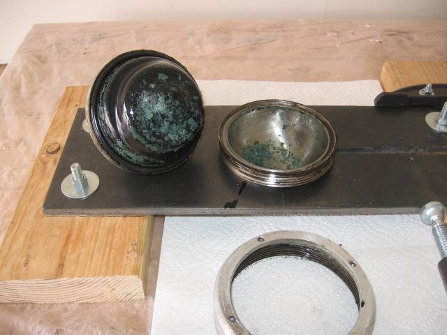 I guess another option if the reservoir is clean would be to recharge them and see how long they stay recharged. Having to unscrew them next time will likely be much much easier now the "welds" have been broken. | ||
leonard stampton Experienced User Username: 1000leonard Post Number: 16 Registered: 3-2018 |
Many thanks to forum members for your encouragement and experience. The weather here in Southern Victoria is cold (for these parts) and wet so I had a day off today from the garage. Tomorrow I will take some photographs and see if I can move them to the internet for your perusal and possible comments. I am waiting for parts to arrive from AUS,UK and China before I can begin the re gassing of the spheres attempt. The previous owner had refurbished spheres fitted during his tenure, possibly 10 years ago. Because of this I do not intend at this point to separate the spheres, even though that is v tempting ! | ||
felipe heuser Frequent User Username: felipe Post Number: 51 Registered: 7-2017 |
Brian...yes and on several occasions asked for advice and received expertise guidance� | ||
Brian Vogel Grand Master Username: guyslp Post Number: 2610 Registered: 6-2009 |
Leonard, If you have access to a syringe and can use a piece of tubing and the connector you will be using when regassing, I'd suggest a "washing out" of those accumulators prior to regassing with denatured alcohol/methylated spirits. If you've got time to run a couple of cycles of denatured alcohol in for a "swish and spit" I'd try it. I'd actually intentionally release all the nitrogen charge before attempting to do so. It's been my experience that most of "the glop" such as shown in Geoff's pictures dissolves when you're in the process of cleaning things with denatured alcohol, which is the "solvent of choice" when working on this system. You could get whatever residue you could get out of the accumulator spheres this way, or at least try. If the fine "salt shaker" holes at the top of the sphere were to clog in the attempt, you know you should separate the halves. Brian | ||
leonard stampton Experienced User Username: 1000leonard Post Number: 17 Registered: 3-2018 |
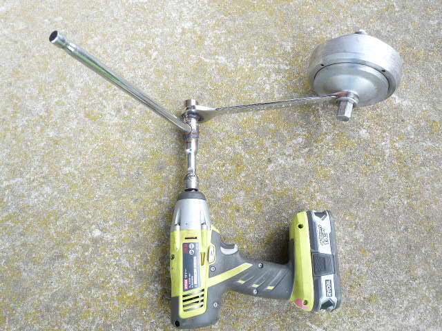
I have already mentioned how the 15/16 inch spanner was modified. The photo shows how it was locked in place on the sphere. The usual 1/2 inch drive Tee bar was welded to a short extension bar which was in its turn welded to an old cut down socket. This provided an engagement for the impact driver. A 3 foot extension pipe was added to the Tee bar to add extra torque to the flat out impact driver. Today I took delivery of a much tougher impact wrench with advertised loosening power of 500 Nm. I will use that next time! | ||
leonard stampton Experienced User Username: 1000leonard Post Number: 18 Registered: 3-2018 |
post photos | ||
Brian Vogel Grand Master Username: guyslp Post Number: 2615 Registered: 6-2009 |
Leonard, See the Formatting page for information on posting photos. I find using the inline image command much easier than the Upload Attachment option, but both work. Images can be a maximum of 640 x 640 pixels. The forum software is quite antiquated, but quaint. Brian | ||
leonard stampton Experienced User Username: 1000leonard Post Number: 19 Registered: 3-2018 |
Brian....as you have spotted the photos did not move from here! I looked at the formatting page instructions but no luck.. I asked by phone one of my sons who is of the opinion that my camera and computer software does not match that on the rr forum. I hope a forum member may be able to help me with this modern day problem ..........Regards | ||
Brian Vogel Grand Master Username: guyslp Post Number: 2618 Registered: 6-2009 |
Leonard, Since the last camera I owned (and that includes on smartphones) that was capable of taking a 640 x 480 pixel image as a native size was well over 10 years ago I know I will need to resize any photo I want to post on these forums. While you can go up to 640 pixels square, most cameras take images that, when the long edge is resized down to 640 pixels, the corresponding short edge will be 480 pixels. If you have only an image or two you want to post it's easy to resize them using MS-Paint, which comes on all versions of Windows, including Windows 10. If you've got a large number of photos you'd like to post here, it's much easier to use Bulk Image Manager to do the resizing on all of them at once and have them saved to a dedicated folder. I often create one called "For_Forums" or "In_640x480" as a subfolder where my "big pictures" are located and have Bulk Image Manager save the resized bunch there. If you happen to have a large photo that's oriented in portrait, Bulk Image Manager will still resize it correctly on the long and short sides, but it will rotate the result, so you will have to rotate those back to portrait orientation yourself. See the following threads: http://au.rrforums.net/forum/messages/30/18341.html http://au.rrforums.net/forum/messages/16947/17784.html Brian | ||
Patrick Lockyer. Grand Master Username: pat_lockyer Post Number: 1945 Registered: 9-2004 |
"Based on what I've found during those rebuilds I would say that none of them was necessary. The diaphragms in all were essentially perfect, and I know that hey had been in service for a very long time." This is a common failing that needs the overhauling of the accumulators. mount the unit in a four jaw chuck and lock. Use a chain wrench to dismantle. Use a ball bearing instead of the plastic ball.  | ||
leonard stampton Experienced User Username: 1000leonard Post Number: 20 Registered: 3-2018 |
Patrick, which side of the diaphragm is the damage on? Is it the Nitrogen side or the brake fluid side? The damage is off centre so I wonder what caused that. Brian I must apologise for my inability to post images on this forum. I have tried your advice along with lots from other people, with no luck! A consensus is appearing along the lines of a serious upgrading of my computer et al is required. There is a hint in there I believe that I need to be included in that upgrade...��.. | ||
Brian Vogel Grand Master Username: guyslp Post Number: 2622 Registered: 6-2009 |
Leonard, I am sorry I have not responded to your private message. Given the age of the actual forums software the probability that your issues with photos is secondary to "upgrade issues" is as close to zero as it comes. Here is an image of the very sentences in this post which are to follow:  ------------------------------------ This is my first image:  and this is my second image  ----------------------------- Provided that the images you attempt to upload once you hit the final "Post this Message" button, and the images you supply for upload are no larger than 640 x 640 pixels, I can assure you they will appear. What goes between the curly braces after the \image command is nothing more than a description of your choosing. If I have many photos that I want to present in a certain order I use these descriptions to help remember that order. Brian | ||
Patrick Lockyer. Grand Master Username: pat_lockyer Post Number: 1947 Registered: 9-2004 |
Leonard, no need to send a private message, nothing to hide! Regards to the diaphragm the damage is common on the nitrogen side when depletion has occurred through many faults. As for the use of old computors with the old non updateable provision like my old desk top running Windows 7, I use the old original Paint Shop Pro CD rom for resizing etc, bought years ago at a car boot sale for a �1. BTW any debris, gunge found then the whole system must be cleaned and flushed including all types of valve assemblies.  | ||
Jim Walters Prolific User Username: jim_walters Post Number: 185 Registered: 1-2014 |
In my professional opinion it is not only false economy but foolish to simply recharge the spheres without rebuilding them with new diaphragms. In the hundreds that I have done the vast majority, I'd have to say over 90%, show damage to the diaphragm. The damage shown by Patrick is on the nitrogen side and is caused by the pressurized brake fluid forcing the diaphragm into the fluid transfer holes when nitrogen pressure is low. A lot of them are full of muck from dissolving brake hoses and corrosion. These are a major safety part and should be properly and correctly overhauled when the pedal pump test shows a low nitrogen charge. Lives depend on these operating properly. SRH8505 SRC18015 SRE22493 NAC-05370 www.bristolmotors.com | ||
Brian Vogel Grand Master Username: guyslp Post Number: 2623 Registered: 6-2009 |
Jim Walters wrote, in part:
I will agree that the damage shown is on the nitrogen side (dry side), but isn't it caused by the diaphragm being forced into the charge port opening by the pressure of the brake fluid when there is very low, or no, nitrogen charge? The fluid transfer holes are on the brake fluid side and are much like salt shaker holes, only smaller. You'd have to have significant overgassing on the nitrogen side to get the diaphragm forced into the neck and all the way down to the fluid transfer holes and that would be on "the wet side." Also, my decision regarding whether to rebuild or not is always directly based on what I know about the history of the car and, specifically, accumulators in question. I rebuilt mine in 2009, and the seal for the nitrogen was not great, so they're due for an overhaul. I would not even begin to consider a full accumulator rebuild on these specific accumulators. A recharging of the nitrogen should be more than sufficient. For accumulators where the last rebuild is unknown a rebuild is very strongly advisable. If the reservoir looks like a sewer a full system flush with a lot of straight DOT3 (before using RR363 or YAK363) is clearly a necessity. I only start tearing everything else apart if issues appear after having done what I mentioned previously. Others will have differing practices. Brian | ||
leonard stampton Experienced User Username: 1000leonard Post Number: 21 Registered: 3-2018 |
 | ||
leonard stampton Experienced User Username: 1000leonard Post Number: 22 Registered: 3-2018 |
Finally I think that I may have negotiated my maze! Brian was kind enough to guide me past my wrong turns...Many thanks. This photo shows the mods made to each end of the poor 15/16 inch spanner. The previous photo is a posed one of the final arrangement that I had used.regards 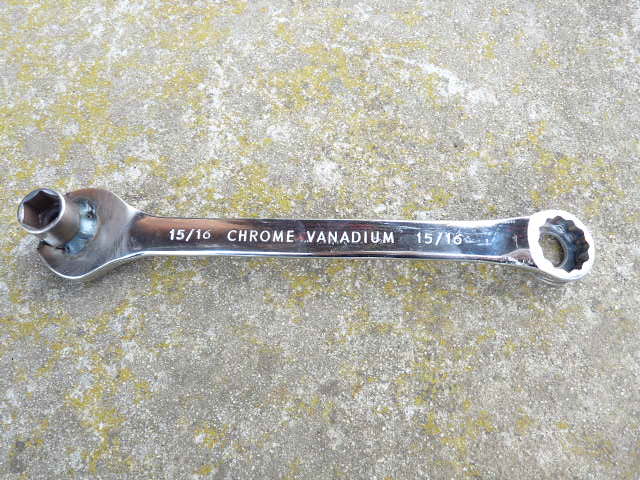 | ||
Patrick Lockyer. Grand Master Username: pat_lockyer Post Number: 1949 Registered: 9-2004 |
To clarify for the gent of many articulate incorrect words of advice. The depletion of nitrogen within the accumulator after time will result in a failing of the diaphragm. The the hydraulic pressure of fluid forcing the diaphragm against the charge port hole will rupture the diaphragm. 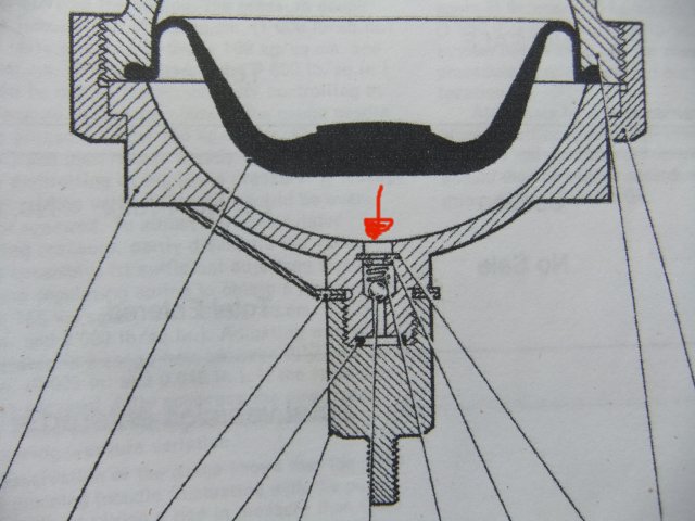 Rebuild both of mine 15 years ago no probs to date. As for a quick charge of nitrogen when depleted this can only be called a short term lash up with the many failings to follow. | ||
Jim Walters Prolific User Username: jim_walters Post Number: 186 Registered: 1-2014 |
Yeah I meant to say charge port. Hazard of posting after a 15 hour day in the shop. SRH8505 SRC18015 SRE22493 NAC-05370 www.bristolmotors.com | ||
Patrick Lockyer. Grand Master Username: pat_lockyer Post Number: 1950 Registered: 9-2004 |
Jim, My posting was not directed at your posting I new what you meant. It was however the failings with the lash up advice given by Brian V with regard to the top ups etc when the accumulator has depleted nitrogen pressure. Overhaul them, not rocket science. | ||
Geoff Wootton Grand Master Username: dounraey Post Number: 2010 Registered: 5-2012 |
Patrick - Brian was referring to the specific case where the history of the accumulators is known. I don't see any problem in topping up the charge if known accumulators have just lost a little pressure. If the nitrogen has completely depleted then of course I would replace the diaphragms due to possible damage from the charge port. | ||
Mark Aldridge Grand Master Username: mark_aldridge Post Number: 563 Registered: 10-2008 |
We are fortunate in the UK that there is a citroen specialist that reconditions Shadow spheres at a price that makes just re gassing a waste of time and effort. | ||
Brian Vogel Grand Master Username: guyslp Post Number: 2624 Registered: 6-2009 |
Mark, Who might that be, and could you send me their contact information? I know I don't have them listed in the UK Parts & Service section of the RR & Bentley Parts, Repair, Restoration & Other Resources Compilation. | ||
Mark Aldridge Grand Master Username: mark_aldridge Post Number: 564 Registered: 10-2008 |
Brian, email is Pleiades.sawtry@gmail.com. Address: Brookside Industrial Estate, 12a Brookside, Sawtry, Huntingdon , PE28 5SD. They are on Facebook, but I cannot find a website. They also supply accumulators and gas springs for SZ series. Mark | ||
Brian Vogel Grand Master Username: guyslp Post Number: 2625 Registered: 6-2009 |
Mark, Thanks much. I have sent an e-mail since I cannot even pull up a Facebook entry for them with the info you've provided. I asked if they'd like to be included in the UK section and, if so, how they'd like to be listed as well as asking about whatever web presence they might have. Brian | ||
Geoff Wootton Grand Master Username: dounraey Post Number: 2011 Registered: 5-2012 |
https://www.facebook.com/Pleiades-Car-Services-154368294714268/ | ||
Brian Vogel Grand Master Username: guyslp Post Number: 2626 Registered: 6-2009 |
Geoff, Just curious what search combination you used on Facebook. I used "Pleiades" coupled with parts of their address. I used the e-mail address at one point, too, but got back nada. They must have had a website once but let the whole thing drop, as the URL they give on the Facebook page "is available." It's not as though I'm an amateur at doing web searches, but I use Facebook itself very seldom and have found its search to be peculiar. Brian | ||
Brian Vogel Grand Master Username: guyslp Post Number: 2627 Registered: 6-2009 |
By the way, the resources list has been updated. Finding people who do accumulator rebuilds, anywhere these days, is almost akin to finding hen's teeth. And those who do them economically are rarer than. | ||
Geoff Wootton Grand Master Username: dounraey Post Number: 2012 Registered: 5-2012 |
Hi Brian I just used a google search on "pleiades brookside" and the first three sites listed were facebook. I have always found the search facilities on facebook to be awful. You can't even specify a country in "find friends". | ||
Patrick Lockyer. Grand Master Username: pat_lockyer Post Number: 1951 Registered: 9-2004 |
As a amateur I fired up the old desk top computor and found this no probs: http://www.mycitroen.dk/library/ds/Red/Parts%20Suppliers%20etc/Pleiades.pdf Easy to overhauld the Shadow ones with a new diaphragm etc etc yourself though! Have fun. | ||
leonard stampton Experienced User Username: 1000leonard Post Number: 23 Registered: 3-2018 |
On Friday last I became one of that select and happy group of forum members that have dismantled their accumulator spheres. First I had to carefully stand on the shoulders of those who had walked before down this path and learn from them. My original intent was only to top up or recharge, however when I did that the complete contents of the accumulator immediately escaped via the malfunctioning non return valve arrangements. My hand now was forced and I was now committed to split the spheres and remove the non return valves to fix their problem. We were having the last gasp of Winter weather here so there was plenty of good workshop and thinking time to be had. More importantly, given the comments on this forum, I was interested to see if a lightly built 76 year old working on his own could manage it. The answer is as I discovered, just about! I built a reasonably heavy duty rig, hopefully see photo. The driving force was supplied by me at the end of two lengths of pipe which produced a lever 8ft long. I then heated the outer ring to about the temperature that I imagined the sphere would experience in service using an electric heat gun. After several heavy pushes at the end of my lever near my maximum effort the ring loosened. Ditto for the second sphere. The diaphragms, in my opinion, were in very good condition with no deterioration, damage or sludge present apart from 4 tiny marks on the brake fluid side that matched perfectly the sphere`s outlet holes. There was a sticky residue on the ring threads which could be ancient congealed brake fluid that added to the dismantling torque needed. 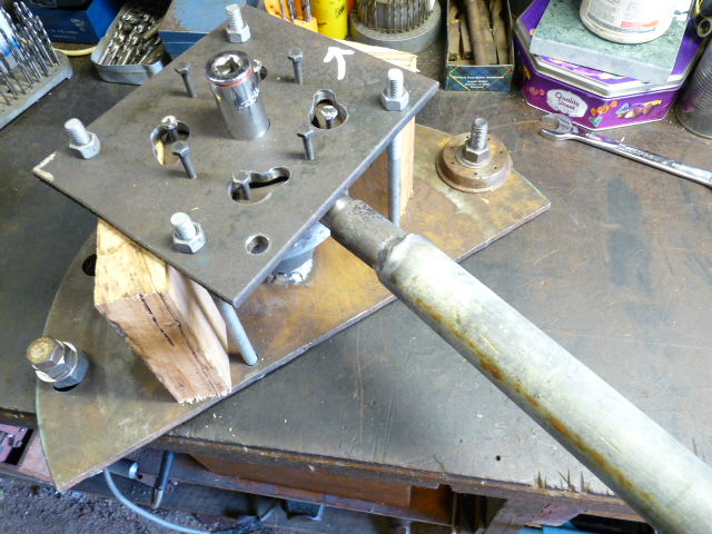 | ||
leonard stampton Experienced User Username: 1000leonard Post Number: 24 Registered: 3-2018 |
some component parts 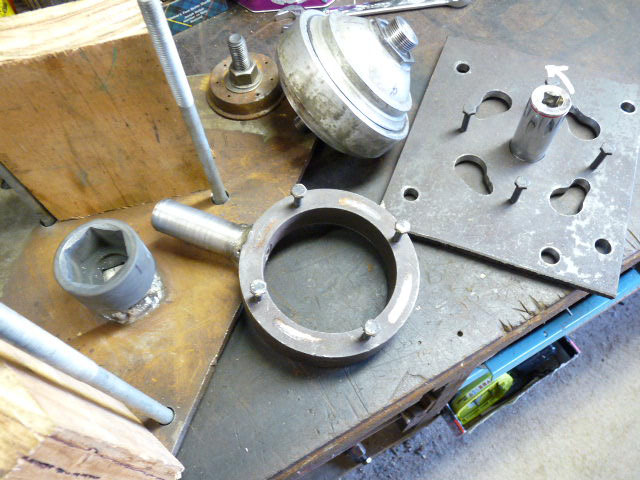 | ||
richard george yeaman Grand Master Username: richyrich Post Number: 995 Registered: 4-2012 |
Well done Leonard that's how we all learn, by having a go. Richard. | ||
Jeff Young Grand Master Username: jeyjey Post Number: 382 Registered: 10-2010 |
Well done, Leonard. Nice contraption! | ||
Geoff Wootton Grand Master Username: dounraey Post Number: 2015 Registered: 5-2012 |
Great work Leonard. Flying Spares sell a much improved valve however it has to be bought as part of their re-conditioning kit. http://www.flyingspares.com/shop/rolls-royce-bentley-shadow-t1-t2-corniche-mpw/silver-shadow-t-1-2-brakes-pads-discs-fluid/shadow-brake-accumulator-sphere-valve/shadow-brake-accumulator-sphere-valve/brake-accumulator-sphere-seal-kit-rh2619p.html | ||
Brian Vogel Grand Master Username: guyslp Post Number: 2635 Registered: 6-2009 |
If you haven't already reassembled the accumulators make sure to use a bit of anti-seize on the clamping ring. It will make removal of same "the next time" (whether you're the one doing it or not) much easier. Congrats on becoming a "member of the club of accumulator rebuilders." At the time I was doing my first set, the cost of having the pin wrench and sphere holding setup custom made, combined with the rebuild kits, cost far less than what I was being quoted to have a single sphere rebuilt here in the USA. While this task is more than a bit of a PITA it is not rocket science and a lot less complicated a task than many others. Brian | ||
leonard stampton Experienced User Username: 1000leonard Post Number: 25 Registered: 3-2018 |
Many thanks guys for your comments, they are much appreciated at this end! I have found the problem with the non return valve that I mentioned earlier. The hard plastic ball has been deformed by the inlet portal, hydraulic pressure and possibly by engine bay heat combined. This poses the question, is a steel ball better here as originally fitted by RR and suggested in this thread? The Flying Spares alternative arrangements have been recommended as the best solution. However the rebuild kits I have been sent that came via Introcar UK have a similar plastic ball. Does any one have a photo of this modification or dimensioned drawings of same? | ||
leonard stampton Experienced User Username: 1000leonard Post Number: 26 Registered: 3-2018 |
image 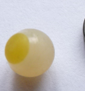 | ||
Brian Vogel Grand Master Username: guyslp Post Number: 2636 Registered: 6-2009 |
If someone has the Flying Spares kit they could measure for you, but the fact of the matter is that if you have the accumulators apart you can come up with the necessary measurements yourself. The improved design is, essentially, a "micro nail with a blunt tip on to which is slipped a very small O-Ring." That blunt tip goes point (so to speak) down in to the charge port opening, the O-ring rests on the small shelf on the inside of the charge port to create the seal, and the spring, etc., completes the arrangement just like it did when a ball was used. It essentially becomes much like a Schrader valve. You just have to size the head on that "nail" such that it fits comfortably within the neck of the charge port without binding and such that it's wide enough that the O-ring slipped on it will seat nicely on the charge port shelf on the inside. When I first saw this I thought to myself, "Not only is it brilliant, it should have been thought of by RR itself decades ago!" Definitely not rocket science if one has the ability to machine small metal pieces. It's interesting, by the way, that many are using the plastic ball on the inside of the accumulator rather than as a "plug" on the end of the charge port opening, to be smashed into place by the charge port cap. Some will insist that the plastic ball is meant to be used inside. To that, I offer the following exchange I had with Flying Spares last year via e-mail. It is to their credit that they corrected the information on their site. -------------------------------------- From Me, to Flying Spares: Hello, I am writing to report what I believe is an error in your description on the website for the accumulator rebuild kit for the SY series cars. As an aside, your redesign of the primary valve on the sphere using the "pin and O-ring" in place of the metal ball is brilliant and works beautifully. In the description on the website it reads, "This kit includes a modified valve which replaces the original nylon ball." The problem is that the modified valve does not replace the nylon ball, but the metal ball. I have now double-checked myself with several other individuals and we all agree that the original design was: 1. Metal ball as primary valve inside the accumulator sphere. This is what the pin and o-ring design replaces. 2. O-ring in the charge port cap is a secondary seal. 3. Nylon ball is a tertiary seal that would be compressed into the port opening itself, in theory creating a seal. These often have to be carefully pried out. My concern is that someone unfamiliar with the accumulator who is doing a first-time rebuild might try to use the pin and O-ring in the physical position where the nylon ball formerly went while reusing the original metal ball as the primary valve. I do not know whether the pin is long enough to displace the metal ball if it were to be placed in to the charge port aimed toward the center of the sphere, but if it were this could create a situation where it would be under significant pressure and could act as a projectile when the charge port cap is removed. I think it would be wise to change the phrasing to say that this modified valve replaces the metal ball and renders the nylon ball unnecessary. It would also help if a set of step-by-step illustrated instructions were included for putting the new valve back in to the bottom half of the accumulator sphere itself. Thank You, Brian Vogel ----------------------------------------------- Reply from Ben Handford of Flying Spares: Brian, Many thanks for your email. You are absolutely correct! I am quite embarrassed because I think I added the note to the website many years ago and you are the first person to helpfully point out my error. As you have recommended we will look to also create a set of instructions to go out with the kits and also to be included on the web page. Thanks for the feedback, much appreciated. Regards, Ben Handford ---------------------------------------------- Based on your photo it appears to me that someone used the plastic ball inside the sphere and that the yellowed part was what would have been the part facing down into the charge port neck itself. Brian | ||
Geoff Wootton Grand Master Username: dounraey Post Number: 2017 Registered: 5-2012 |
Brian It appears the Introcar kit now uses TWO plastic balls. https://www.introcar.co.uk/accumulator-kit-rh2619-p150 If I were Leonard I would try and return the Introcar kit and buy a FS kit. Else get a local engineering workshop to make two pins. The dimensions could be taken from the charge port on the (hemi)sphere. | ||
Brian Vogel Grand Master Username: guyslp Post Number: 2637 Registered: 6-2009 |
Geoff, Given that Leonard lives in Australia it may be that returning these kits would not result in paying exorbitant postage, eating up a significant portion of the original purchase price. If so, I'd definitely return them. There is no doubt, none, that Flying Spares finally "nailed it" (no pun intended) with the design they came up with. I wouldn't be surprised if even the O-ring in the charge port cap might not be necessary, but I'd never omit that anyway. I still think that using a hydraulic/pneumatic sealant on the charge port cap threads as the "final touch" (and which is, of course, able to be removed, it's not permanent thread locker) after using the FS kit is the best way to make these things as nitrogen sealed as they're ever going to get. Vixen Horns Hydraulic-Pneumatic Fitting Sealant Brian | ||
leonard stampton Experienced User Username: 1000leonard Post Number: 27 Registered: 3-2018 |
Geoff, you are quite correct each kit does contain two plastic balls and an explanation that one of them is to be used inside the sphere after discarding the steel ball. My spheres had a plastic ball inside that had become distorted and once disturbed would not of course re seat. Returning the rebuild kits would have extended the job even further and living here waiting for post to arrive can be frustrating. Anyway as I am able to make parts after a lifetime involved with the live steam hobby I made my own today! Such enthusiasm must have been caused by the onset of Spring weather. I have reassembled one sphere and recharged it. If there is no leakage tomorrow I plan to do the same to the other sphere and then fit them in place. Brian, I used anti seize on the ring threads and Loctite hydraulic sealant on the charging cap. Why RR did not change their badly designed non return valve is a thorny question indeed. Possibly they had moved on, had bankruptcy to worry about, did'nt accept that there was a problem anyway? etc. | ||
Brian Vogel Grand Master Username: guyslp Post Number: 2638 Registered: 6-2009 |
Leonard, Just remember when you are fitting them to the ACVs to tighten them according to the torque tightening figure in Chapter P. This is another area where many grossly overtighten. I gather you have a nitrogen tank relatively close to hand. That's handy, and unusual. Brian | ||
John Jenkins Unregistered guest Posted From: 31.53.43.219 |
I gather you have a nitrogen tank relatively close to hand. That's handy, and unusual. Brian I have found here in the UK, that some garages that do air conditioning, have nitrogen gas which is used to purge the air-con and check for leaks after a repair, so it is not a problem to recharge accumulators if you have the necessary connections, etc. Jake. (Message approved by david_gore) | ||
leonard stampton Experienced User Username: 1000leonard Post Number: 28 Registered: 3-2018 |
charge cap 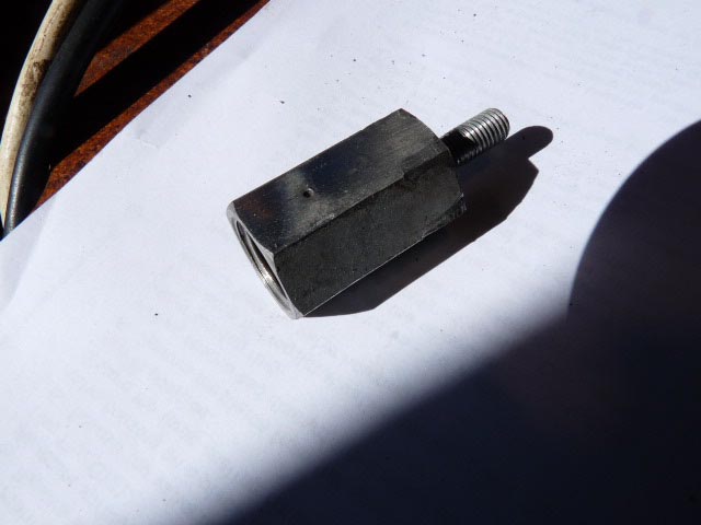 | ||
leonard stampton Experienced User Username: 1000leonard Post Number: 29 Registered: 3-2018 |
When cleaning my accumulators prior to recharging u I discovered that the charge caps had a small hole around 1.2mm diameter in each. This was intended to be a safety feature I imagine by venting any pressure build up that would be possible if the non return valve was leaky. However as I intended to use thread sealant as a back up along with a cap O ring I sealed each hole with a steel plug silver soldered in place. My RR is a 1977 S Shadow 2, do other members have this vent hole on their vehicles? I used a disposable N2 cylinder intended for beer transportation if that is the right word. To connect up I used a paint ball charging braided hose with a quick connect coupling and pressure gauge. There is an unusual outlet thread on the N2 cylinder 10mm X 1.0mm so an adaptor has to be made. Both items are readily available on the internet at low cost. The cylinder is pressurised to around 1300psi, with careful use I was able to recharge both accumulators to 1000psi each using just one cylinder of gas. Regards | ||
Patrick Lockyer. Grand Master Username: pat_lockyer Post Number: 1957 Registered: 9-2004 |
I read "If you haven't already reassembled the accumulators make sure to use a bit of anti-seize on the clamping ring. It will make removal of same "the next time" (whether you're the one doing it or not) much easier." Rubbish, carry out clamping ring assembly dry and torque to 270 LB FT. Use of anti seize will allow over tightening of the joint at 270 lb ft and after years of engine heat etc will make dismantling of the clamp even harder to remove. | ||
Kelly Opfar Prolific User Username: kelly_opfar Post Number: 208 Registered: 7-2004 |
Leonard, I'm intrigued that you found a fitting for the sphere charging port on the internet. I stand ready - and eager - to be corrected but I've never seen one for sale besides those that I offer on my site. I didn't invent them - clearly they are based on an existing design but I haven't found it. I machine couplers as fast as I can but I still have to charge $40USD ea. I'd love to buy them in bulk and offer them for less. I'm concerned that you may have used a female 3/8"-18 NPT fitting instead of a 5/8"-18 UNF coupler. The NPT pipe fitting will screw onto the charging port partway because they both have 18tpi and have a similar diameter but the NPT fitting has a tapered thread. This means that a maximum of one thread is engaged in holding the charging port in place under 1000lbs. of pressure. That terrifies me. http://www.BritishToolWorks.com | ||
Geoff Wootton Grand Master Username: dounraey Post Number: 2019 Registered: 5-2012 |
Hi Kelly It is such a gift that we have someone with your engineering expertise on this forum. As far as I am aware no-one manufactures the correct fitting for the charge port on RR accumulators, other than yourself. I researched this in detail when I was looking to recharge my accumulators, five years ago, and the consensus was to use a watts A762 coupler with a schrader valve. Here is the combination I used, as advised by several sources. 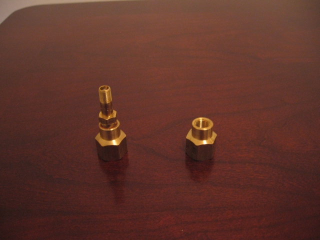 The Watts A762 has the erroneous 3/8" NPT thread. It bothers me that I unwittingly placed the staff at the workshop that recharged my accumulators in danger. Needless to say, when I next need a re-charge I will be buying the correct adapter from British Tool Works. Geoff | ||
leonard stampton Experienced User Username: 1000leonard Post Number: 31 Registered: 3-2018 |
Kelly, In Australia there is an almost impossible range of screw threads used in machinery. We pay lip service to the metric system here but continue with threads the had their origins in UK US and France amonst others. Engineering measurements is another topic for endless discussion but not here right now! Anyway over the years I have grown accustomed to connecting different systems together and have a large assembly of threading tools to do this. So to put your mind to rest my connection to the accumulator sphere (home made) has the correct parallel thread 5/8inch X 18TPI UNF thread. I also manufactured the connector at the other end of the braided hose (Chinese with metric threads)......Regards 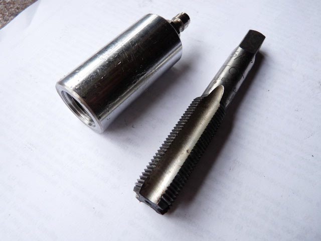 | ||
Jim Walters Prolific User Username: jim_walters Post Number: 191 Registered: 1-2014 |
When I made up my charging rig several years ago I had to machine up a 5/8th X 18 UNF adapter for the 'tap', for want of a better description. The tap fitting was something I had in a large box of hydraulic fittings. It is made to turn a T on the top to press a pin to depress a check ball to charge and/or read the pressure on a pressure cylinder of some sort. I'll take a picture of it tomorrow and post it to see if someone recognizes it. SRH8505 SRC18015 SRE22493 NAC-05370 www.bristolmotors.com | ||
Jim Walters Prolific User Username: jim_walters Post Number: 192 Registered: 1-2014 |
Here is my charge valve: 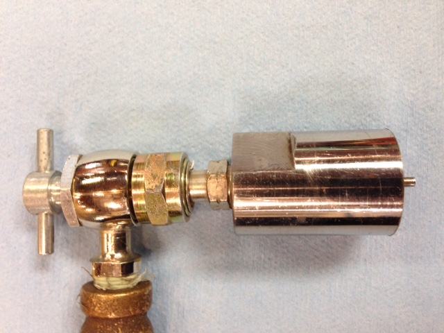 And this shows the valve separated from the adapter I made. The pin extension abuts the threaded end of the T of the valve to open the charge port ball bearing to read the pressure in the sphere. This way I can be absolutely sure that the spheres I rebuild are fully charged when filled with nitrogen. 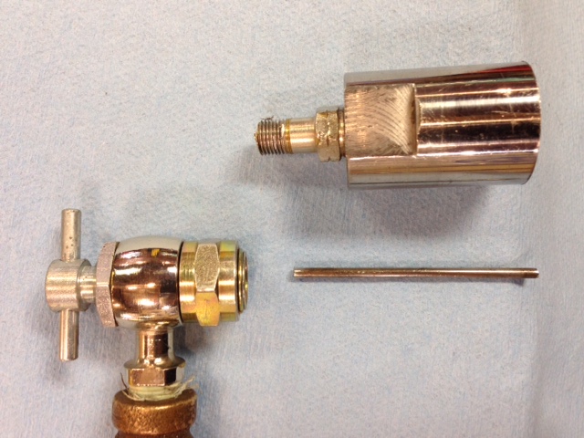 SRH8505 SRC18015 SRE22493 NAC-05370 www.bristolmotors.com | ||
Alan Dibley Prolific User Username: alsdibley Post Number: 160 Registered: 10-2009 |
I have a theory about the torque needed to unseal the two halves of accumulators. Background: In the Citroen world it is accepted that spheres should be tightened to only finger tight (plus a tiny bit more if you are nervous). The reasons are:- 1) if there is even a small amount of pressure in the system the thread is locked solid by friction. 2) the seal is made by internal pressure forcing the O-ring out against the steel enclosing it. A similar system, with a rubber tube, is used on pipe unions/joints. It works (Trust me, I've worked on dozens of oleo-pneumatic Citroens from that era). When RR accumulators were designed the RR/Citroen liaison was just beginning and the news had not reached the responsible area. I propose that if the spheres were assembled with just enough torque to make light metal-to-metal contact between the halves the result would be much easier dismantling. Discuss (politely). Alan D. | ||
Patrick Lockyer. Grand Master Username: pat_lockyer Post Number: 1958 Registered: 9-2004 |
Alan, I agree and also carry out the above with years of service proved, needless to say that the 270 LB FT torque was stated however to use anti seize with that torque will make them almost impossible to dismantle in later years. BTW, Check for nitrogen pressure do a pedal test with the working dash warning lights circuit 1-2. To charge set regulator to 1100 lbs when completed whack a new steel ball bearing under the charging cap to complete the seal!. Cripes what a drawn out thread for a simple job. | ||
Brian Vogel Grand Master Username: guyslp Post Number: 2639 Registered: 6-2009 |
Alan, Also, given the number of threads involved, even if just somewhat past finger tight (which I would do) it's not ever likely to budge. You are not the first person to mention this on either RR forums or Citroen forums, and the amount of positive response from professionals definitely supports the proposition. Even with less torque, I'd still use a bit of anti-seize, as there seems to be a lot of "welding by ever-so-slight corrosion" that occurs, too, and this would eliminate that, or at least reduce it very greatly. It's also interesting if you have any aircraft mechanics (in particular) amongst your group of acquaintances to see how they look at you funny if you call 1000 PSI in an accumulator "high pressure." That's beneath the very lowest end of what is typically used in nitrogen charged accumulators that go on aircraft. When I had a friend of mine who's in that business do the regassing on mine when I rebuilt them he commented about how really overbuilt they were for the low pressure (relatively speaking) that they were intended to contain. Brian | ||
Omar M. Shams Grand Master Username: omar Post Number: 1665 Registered: 4-2009 |
I would like to agree with Alan and Patrick. It makes perfect engineering sense. | ||
Jean-christophe Jost Frequent User Username: jc_jost Post Number: 53 Registered: 3-2016 |
I know there are ready to use sealing kits, but does anyone know about the diaphragm size and measurements, and in general the specifications for the other spare parts (o rings, washers) used for the valve/accumulator servicing ? | ||
Brian Vogel Grand Master Username: guyslp Post Number: 2649 Registered: 6-2009 |
I know of no "over the counter" functional substitute for the RR/Bentley SY accumulator diaphragm. As I've said in the past, though, once you have them apart you can determine whether it's even necessary or not. As for what's in the various kits, see: RR/Bentley SY Seal Kits for Sale. Although I have some of the kits pre-made for sale, I document all the contents for anyone who wishes to purchase the components themselves. Brian | ||
Jean-christophe Jost Frequent User Username: jc_jost Post Number: 54 Registered: 3-2016 |
Thanks a lot Brian | ||
Jean-christophe Jost Frequent User Username: jc_jost Post Number: 57 Registered: 3-2016 |
Hi, When I asked them whether they could just "top up" my accumulators with nitrogen, a pretty renowned RR garage here in France replied something like : Do not ever regas an accumulator without changing the diaphragm. This can done by Citroenists because mineral oil isn't corrosive, but RR363 is corrosive and an old diaphragm is certainly dead. It's useless or even dangerous to regas. What is your opinion ? | ||
Christian S. Hansen Grand Master Username: enquiring_mind Post Number: 1052 Registered: 4-2015 |
They like selling diaphragms? | ||
Brian Vogel Grand Master Username: guyslp Post Number: 2707 Registered: 6-2009 |
They love selling diaphragms as a cash cow. Having now ripped apart three of my own as well as being up close and personal with several additional rebuilds to a one they did not need a replacement diaphragm. I still have one of the two that I kept when I rebuilt the accumulators on SRH33576, and these were almost certainly at least 20 years old or more, and it's almost indistinguishable from the replacement for it. They're in an environment where one side is nitrogen and the other is a fluid relatively low in oxygen, and the elastomer (EPDM) used has what even manufacturers of the stuff say is an almost perpetual shelf life if kept away from direct light. It's interesting, too, that either Crewe or one of the makers of diaphragms changed the design slightly over the decades. One very old one I saw was not all that much thicker at the center than along the circumference, and this is what gets pushed up into the "salt shaker holes" at the top of the accumulator (which may have changed themselves in the SY2 accumulator) when it is being recharged or when you do brake pedal tests draining the fluid from the accumulator. The new ones I used have a much, much thicker "blob" at the center where it would be pushed into these holes, minimizing (eliminating, I'd say) the possibility of tearing in that location. Now, for a few photos from an accumulator taken off of SRH33576 for a complete rebuild in 2012. All of these are pre-cleaning and the fluid visible on the lower half got there when taking things apart, it was not there due to diaphragm compromise. These things are residually "soupy" with the RR363 that remains in the ridges in the diaphragm. 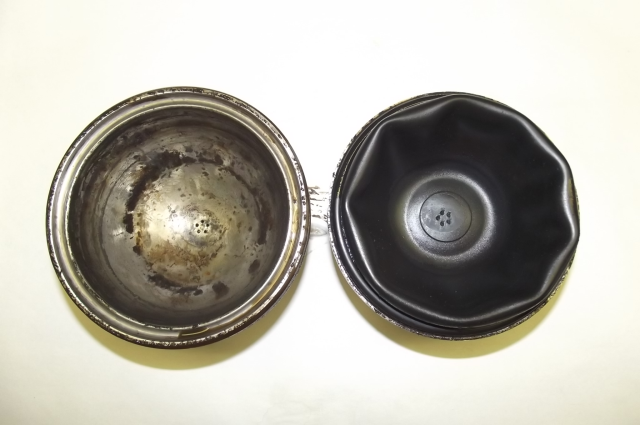 Accumulator Upper Fluid Half & Diaphragm Fluid Side  Upper half of accumulator - Fluid side - "Salt Shaker Holes" visible 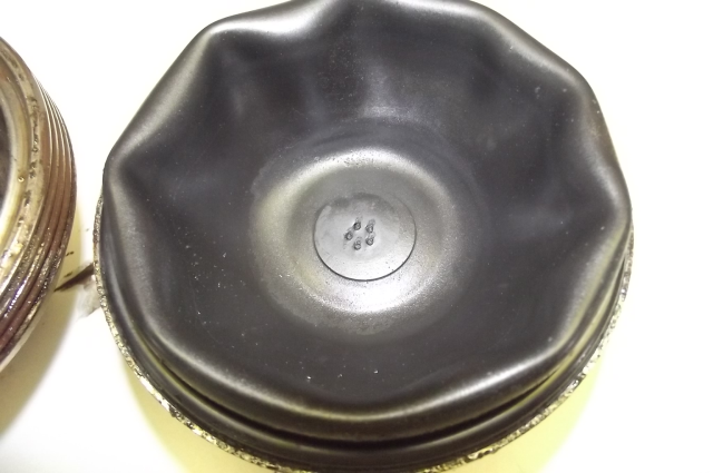 "Vintage" used diaphragm - Fluid side 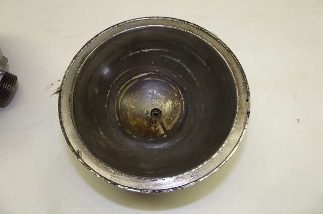 Accumulator Body, Lower/Nitrogen Side showing charge port inlet hole 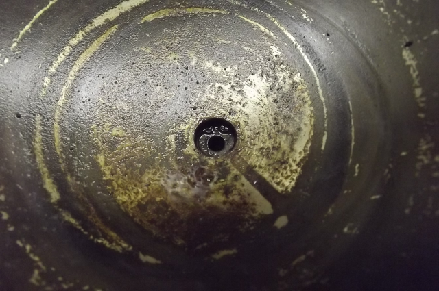 Close up of charge port inlet showing circlip that holds seating washer, spring, and primary valve (steel ball) in place 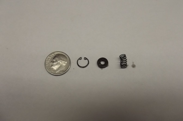 Circlip, seating washer, and spring with U.S. dime for size reference Brian | ||
Christian S. Hansen Grand Master Username: enquiring_mind Post Number: 1053 Registered: 4-2015 |
Yes. In essence the dealer's premise is absurd for it proposes that the system as designed will self destruct. Were that true, there would have by now been a tsunami of brake failures. As usual and greatly appreciated, Brian's analysis is detailed and appropriate. A Merry Christmas to all, and to all a Good Night! | ||
Jean-christophe Jost Frequent User Username: jc_jost Post Number: 58 Registered: 3-2016 |
Brian your pictures are precious because I don't have time / skill to access the inside of my accumulators. I want to say how valuable this forum is. You expert guys are great to read. Happy Christmas all. | ||
Brian Vogel Grand Master Username: guyslp Post Number: 2709 Registered: 6-2009 |
Jean-Cristophe, While I can't say whether or not you have the time, you almost certainly have the skill. Once the nitrogen is released (which can be done with a center punch, repeatedly tapping the steel ball in the charge port while it's aimed *AWAY* from you or anyone else) all the rest of it is brawn. It's two steel half spheres, an EPDM diaphragm between 'em, and a clamping ring. I'd never touched them until, well, I touched them. This is not rocket science. Even the Accumulator Control Valve, fabled to be hellishly difficult/confusing, is not rocket science. The thing I hated working on the most was the Height Control Valve, and not because it was difficult to understand but because getting the two X-ring seals in is just an incredibly tedious job, or was for me. Brian, who also wishes all who celebrate Christmas a very merry one - and a marvelous 2019 to all! |