| Author | Message | ||
Geoff Wootton Grand Master Username: dounraey Post Number: 1821 Registered: 5-2012 |
I know there is already a thread running, related to this topic, but I did not want to hi-jack it, hence the new thread. I am about to fit a replacement master cylinder and am having difficulty following the SY1 workshop manual, section G15, page G75. The actual replacement is straightforward however I am not clear how to set up the "on stop" (master cylinder) and "off stop" (distribution valve) clearances in the brake linkage. The manual says to "Unscrew the four 2 B.A. bolts which secure the 'OFF' stop bracket to the side support plates sufficiently to enable the bracket to be moved on it's slots" They are referenced as Number 4 in the workshop diagram: 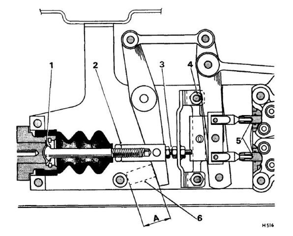 The thing is, when I look at my rat-trap there are no slots to move the bracket to set the "off stop" clearance and the bolts look much larger than 2BA. Also, this seems to be a very clumsy way of setting a very fine clearance. Below is a pic of my rat-trap, viewed from below. The arrowed bolts are the ones denoted 4 in the diagram. There are obviously no slots and the bracket does not appear to be designed to be moved. 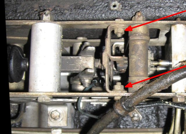 The thing is, I know this method may have been superseded but the manual does not give an updated procedure. I'd appreciate any advice. I can't get off the starting blocks here. Geoff | ||
richard george yeaman Grand Master Username: richyrich Post Number: 852 Registered: 4-2012 |
Hi Geoff any I have done I only use the measurements at 6 which is 20mm approximately. Richard. | ||
Geoff Wootton Grand Master Username: dounraey Post Number: 1822 Registered: 5-2012 |
Hi Richard I can see how the threaded rod and locknut at 2 are used to vary this measurement. Thanks for confirming it works in practice. It would be nice if I could make sense of the manual. I can see from the diagram that the two distribution valve push rods appear to mounted on a short lever that pivots on the main lever. This is presumably a setup to make sure each valve is operated equally. I suspect the area marked number 3 is where the distribution valve clearance is set. I just wish the manual would confirm this. Geoff | ||
Christian S. Hansen Grand Master Username: enquiring_mind Post Number: 623 Registered: 4-2015 |
Geoff... Are you SURE that there are no slots, as it is not obvious to me from the photo. It is entirely possible that the slots are very short and on the center "U" shaped bracket and hidden under the washers rather than on the side frame. It looks to me that the clearance at "6" is set first with the threaded rod and locknut and only then the clearance at "3" is set by moving the internal "U" shaped brackets held by the bolts at "4". What's confusing is that instead of "four" bolts, there appear to be only "two". . | ||
Paul Yorke Grand Master Username: paul_yorke Post Number: 1916 Registered: 6-2006 |
Geoff - all I can say is don't mess with any of the other measurements or linkages. If you are only changing the master cylinder only adjust the master cylinder. Even when I've replaced distribution valves they have just slotted in with no problem. Make sure everything is free and well lubricated, then leave it alone. Only problems I've had come in to be looked at have been tinkering related! Once everything is warm ( so the mater cylinder operating rod etc has expanded ) Adjust it so there is slight play at point 1 on your diagram. (Feel the play on your old one before removal.) You may need to swap the rod from your old master cylinder to the replacement. If you drain and collect the fluid from the rear reservoir you should manage to stop it ending up in your armpits ;) Have fun. | ||
Robert Noel Reddington Grand Master Username: bob_uk Post Number: 1551 Registered: 5-2015 |
take note of what Paul said about the car being warm. If rear brakes start to bind on a test run, stop and back off master cylinder push rod till brakes fully released. | ||
Patrick Lockyer. Grand Master Username: pat_lockyer Post Number: 1575 Registered: 9-2004 |
"test run" don't get run over! Geoff have tested the old master cylinder first? | ||
Geoff Wootton Grand Master Username: dounraey Post Number: 1823 Registered: 5-2012 |
Hi Folks As always, many thanks for all your help and comments. I am now clear as to how to progress - keep it simple. Patrick - the old master cylinder is probably ok but I've decided to upgrade to a 3/4" unit for the better pedal "feel" and ease of bleeding the system. Paul - I've been up to my armpits with brake fluid for the last two weeks. I'm hoping to block off the feed pipe before the reservoir drains, so that I don't have to re-bleed the high pressure circuits. I just know it's all going to go wrong. I will be taking another bath in the stuff. Geoff | ||
Patrick Lockyer. Grand Master Username: pat_lockyer Post Number: 1577 Registered: 9-2004 |
With the larger 3/4" master cylinder bore will mean more rear brake bias to the rear. Heavy emergency braking and the centre of gravity of the vehicle effectively shifts forward, putting more weight and more momentum on the front tyres. The rear of the car becomes lighter and the greater braking force with the larger bore M/C could IMO cause a lockup. Maybe uneven pad wear on the rear calipers! | ||
Geoff Wootton Grand Master Username: dounraey Post Number: 1824 Registered: 5-2012 |
Hi Patrick I accept what you are saying but I have heard many reports from owners who prefer the 3/4" unit. Martin Taylor being the most recent on the "brakes are breaking my heart" thread. When I have upgraded my car (or downgraded, depending on one's opinion), I will carry out some emergency stops to see if I consider rear wheel lockuo to be a potential hazard. I will report back when I have changed the master cylinder, which I am hoping to do in a week's time. Geoff | ||
Paul Yorke Grand Master Username: paul_yorke Post Number: 1918 Registered: 6-2006 |
Lol Geoff. As long as you refill the reservoirs before you start the engine the high pressure circuits will be fine. The high pressure problems come from trying to thread pipes in quickly whilst 363 is running down your arms  high pressure on you! Lol. Patrick... the theory makes sense but practice makes perfect. Sense. The g valve takes care of things plus the power brakes come on sooner. Well from experience it certainly works. | ||
Patrick Lockyer. Grand Master Username: pat_lockyer Post Number: 1578 Registered: 9-2004 |
Geoff Paul 363 running down your arms! If the reservoir cap seals are ok just block off the vent holes, you loose a little fluid to start with but soon stops. Conventional master cylinder reservoir types cover with plastic bag sealed with elastic band. Carry out repairs at your leisure. Paul, trying to get my head round the fact? "the power brakes come on sooner." | ||
Paul Yorke Grand Master Username: paul_yorke Post Number: 1919 Registered: 6-2006 |
Patrick, when you press the pedal the power brakes don't come on until resistance at the master cylinder is met. The sooner that is met , the sooner the power brakes come on. An extra inch or so is 'wasted' with the smaller master cylinder as all the slack is taken up, and then once the slack is gone, the master cylinder and power circuits begin to work at the same time. The larger master cylinder does not start using JUST the master cylinder earlier and then operate the power brakes at the same point that it used to with the smaller cylinder. ONLY IF YOU HAVE A MASTER CYLINDER - Also as a little fun tester for yourself Patrick, find a safe hill that is gentle, straight, and has plenty of room and no traffic. Drive down the hill and do an emergency stop. Next go back up the top - turn off the engine and depressurise your accumulators and let the car roll (KEEP YOUR HAND ON THE KEY AND BE READY TO RESTART THE ENGINE) use the master cylinder to induce a skid. (BE READY TO START THE ENGINE!!) I NEVER ever move a Shadow or Spirit without the engine running. I've been fitting the larger one for 30 odd years with no odd brake wear or skidding. I will have a go and try sealing the caps next time TBH though, most cars will benefit from a brake fluid change so get drained anyway. | ||
Geoff Wootton Grand Master Username: dounraey Post Number: 1825 Registered: 5-2012 |
I finally, finally understand how the rat-trap works. Thank you Paul. Your expertise is so greatly appreciated. I just couldn't figure out, from studying the above diagram, how the master cylinder would have any effect on the lever that operates the distribution valves. I now get it - the master cylinder when it comes on takes up all the slack in the system and the distribution valve lever is effectively "pushed forward". The only outstanding question is whether the "play" in the levers is designed in (eccentric cam etc) or whether the system just takes advantage of the natural "play" in the system. Either way, it doesn't matter - the effect is the same. This explains why a 3/4" master cylinder is such a good upgrade. Geoff | ||
Martin Taylor Prolific User Username: martin_taylor Post Number: 106 Registered: 7-2013 |
The 3/4 cylinder gives less pedal travel before the balance levers push on the distribution valves. It feels more like other cars, I imagine the same amount of fluid is pushed to the rear calipers, it is just done with less pedal stroke. Expect brake fluid in your hair, rubber gloves over your sleeves will stop it running into your armpits! | ||
Patrick Lockyer. Grand Master Username: pat_lockyer Post Number: 1580 Registered: 9-2004 |
Martin yes The main factor that is going to come into play is the bore sizeing of the master cylinder which I had it the wrong way round, it has a lot to do with capacity as well as pressure. A larger bore size in a master cylinder should produce more pressure but that is actually not the case. In most cases the smaller the bore of the master cylinder means the more pressure you are going to have at the caliper assembly, if you have a larger bore master cylinder it is actually going to produce less pressure, its actually going to give you a harder pedal feel as an end result as Paul has said. I would have thought the pressure at the caliper needs to be somewhere between 800 and 1,200 psi. I have left the original type m/c on mine. | ||
gordon le feuvre Prolific User Username: triumph Post Number: 217 Registered: 7-2012 |
The linkage system is a hang over from pre war days. The mechanical servo eccentric would not come into play until foot brake operated rear shoes which would come on first. This would allow servo eccentric to operate thus moving servo lining onto spinning flywheel face of servo thus bringing servo effect onto linkage which tried to twist everything thus pulling rods to apply brake cables and then when hydraulic brakes came, master cylinder. With Shadow as Paul says, sooner master cylinder takes up slack by applying rear brakes this then has effect (by linkage design) to push the two pins forward into the distribution valves and allow HP fluid to calipers. So longer it takes for master cylinder to work, more pedal travel etc. Citroen DS21 just had rubber covered "button" on floor in place of brake pedal. The brakes were very much ON or OFF. R-R didn't like this ,so designed linkage with master cylinder, replacing it at chassis 22118 with a rod/spring/rubber cone to do same job as master cylinder! | ||
Geoff Wootton Grand Master Username: dounraey Post Number: 1837 Registered: 5-2012 |
I removed the master cylinder from my car this afternoon. The Land Rover S2 substitute appears to be a direct plug in replacement. It is the lower one of the two in the picture. 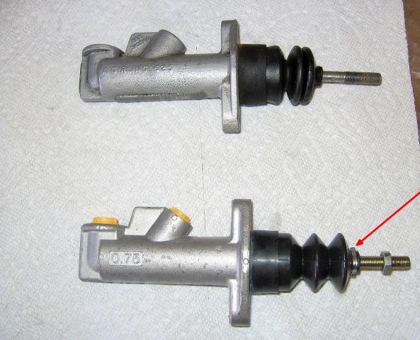 All the threads and dimensions are the same, other than the new MC being 3/4" and the original 5/8". Even the push rod has the same diameter and thread. The only difference is the clip that I've arrowed in the picture. The problem is that when I rotate the pushrod, which I will need to do to fit the m/c, it twists the rubber boot. Should I carefully remove it with some snips and throw it away or should I try to extract and replace it when the master cylinder is in place. I'm thinking removing it completely is the best way to go. Is this the best course of action? Geoff | ||
richard george yeaman Grand Master Username: richyrich Post Number: 858 Registered: 4-2012 |
Geoff I would remove the clip, it would be he same as your old one which doesn't have one. Richard. | ||
h_kelly Prolific User Username: h_kelly Post Number: 237 Registered: 3-2012 |
Geoff, you might consider a tiny plastic cable tie when fitted if desired .I would follow Richard on this one,the original has none and the repair kit don't supply one. | ||
Paul Yorke Grand Master Username: paul_yorke Post Number: 1940 Registered: 6-2006 |
You can usually ease it open slightly and spa� a little wd40 in so it spins. Not important unless you intend to some wading like Range Rover drivers enjoy | ||
Geoff Wootton Grand Master Username: dounraey Post Number: 1838 Registered: 5-2012 |
Richard,Hubert,Paul - Thanks. You've confirmed I should remove the clip completely. It occurs to me the rat trap cover offers a lot of protection as well. As for wading waist deep in water - I don't even like driving the car in the rain - lol. Geoff | ||
Paul Yorke Grand Master Username: paul_yorke Post Number: 1941 Registered: 6-2006 |
I found this video I made for somebody a while ago. I'd forgotten about it! https://www.facebook.com/Paul.J.Yorke/videos/o.264698327061631/10155832453464371/?type=2&theater¬if_t=video_processed¬if_id=1509719773525226 | ||
Geoff Wootton Grand Master Username: dounraey Post Number: 1855 Registered: 5-2012 |
I thought I'd wrap up this thread. I fitted the 3/4" Land Rover S2 master cylinder and it's made a vast improvement. The system bled first time and the pedal feel is better than I ever managed to get with the old 5/8" M/C. Thanks for all the help and advice. Geoff | ||
Christian S. Hansen Grand Master Username: enquiring_mind Post Number: 729 Registered: 4-2015 |
In the diagram in the first post of this thread, what should the clearance at #3 be, presumably adjusted by the locknut and threaded rod at #2? | ||
Geoff Wootton Grand Master Username: dounraey Post Number: 1905 Registered: 5-2012 |
Hi Christian As you said, the clearance is adjusted by the threaded rod and locknut. The figure at 3 is not given in the manual, but 1 is stated as 5 to 10 thou. The way I interpreted the manual was; at 3 there is no gap as the weight of the entire pedal linkage is supported here. I figured you do not want all that weight pulling on the master cylinder plunger, which would be the case if there was a gap at that point (3). The rod is then set with a 5 to 10 thou clearance at 1 to make sure the master cylinder is not set up with the plunger partially depressed. Since you cannot get a feeler gauge in at point 1 and also as the manual is fairly vague about the precise gap (5 to 10 thou) I just pulled back the rubber cover and made sure the rod had a slight movement of around 10 thou when the linkage was at rest. I should add that the manual is not clear about this - this is my interpretation. | ||
Christian S. Hansen Grand Master Username: enquiring_mind Post Number: 731 Registered: 4-2015 |
Geoff... Here is the diagram again. It is the poster child for confusing and unclear. 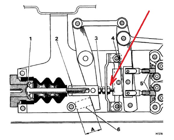 My take on it is that loosening the nut at #2 and then turning the MC rod adjusts the clearance at "A", not the gap at #3. The text indicates that the first thing to do is to open the #3 clearance (the off stop) by loosening the nut not numbered but identified by my red arrow. The clearance (MC rod free play?) at #1 is barely noted but when you adjust the clearance at "A", it would seem that the clearance at #1 is simultaneously reduced to zero since the MC rod is being pushed to the left as well. The inference from the text is that once the clearance at "A" is set, then you go back and reset the off stop clearance at #3 and lock with the nut (red arrow). Nowhere does it indicate what this gap should be. In another thread, Paul indicates that there must be clearance at #1 (or alternatively at #3 when MC rod is pushed to the left as pedal is pushed) to allow for expansion of the MC rod when it heats up. Presumably (perhaps) this is the .005 to .010"? This same gap at #3 is also relevant to the pedal travel free play. Today as I was observing the area on my own car at ACME, that gap had been set to about .040" which translated to about 3/8" to 1/2" pedal free play before the MC rod began to move to the left and activate the MC. It seems that there must be some clearance there otherwise the MC rod will not go completely off and the rear pads will drag. Very confusing. . | ||
Geoff Wootton Grand Master Username: dounraey Post Number: 1906 Registered: 5-2012 |
Hi Christian I still maintain there should be no gap at #3. My reasoning is that the adjuster (red arrow) is used to set the distribution valve clearances (#5). It is completely separate from the master cylinder adjustment. When the master cylinder is installed and set the adjustment is solely through the adjuster at #2 such that there is 5-10 thou clearance at #1. i.e. there should be no tension on the MC push rod. Having the gap at #3 set to 40 thou means that the master cylinder push rod is acting as the stop for the distribution valves, which I cannot believe is correct. | ||
Patrick Lockyer. Grand Master Username: pat_lockyer Post Number: 1786 Registered: 9-2004 |
"Having the gap at A set to 40 thou means that the master cylinder push rod is acting as the stop for the distribution valves, which I cannot believe is correct" Once the lever hits the STOP then the m/c is redundant and the balance lever assembly comes into play triggering the upper and lower distribution valves, be it alarming on the brake application with the pedal close to the floor. Simples! BTW the no 2 this is adjustment with the gauge at 0.40mm for the stop position. The master cylinder rod adjustment no 3 for longer or shorter rod to the required free travel set at 0.13mm to 0.25mm. | ||
Christian S. Hansen Grand Master Username: enquiring_mind Post Number: 734 Registered: 4-2015 |
No disrespect to anyone, but I can only say that recent posts make no sense when combined with observation of the system in real time rather than simply words, references to non-applicable systems, or diagrams. I only wish that I had taken a video yesterday when the car was up in the air and it was being demonstrated to me in real time, at which point everything made perfect sense, both designed function and adjustment...to me at least. Later today I will try to make some diagrams to explain what is happening and perhaps make things clear. . | ||
Patrick Lockyer. Grand Master Username: pat_lockyer Post Number: 1787 Registered: 9-2004 |
This may help, early car set up. 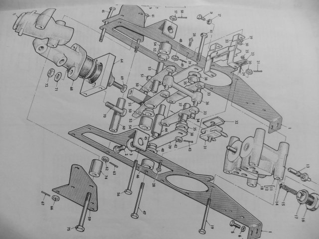 | ||
richard george yeaman Grand Master Username: richyrich Post Number: 937 Registered: 4-2012 |
One thing in this whole thread that stands out as good advice is stated in a post by Paul Yorke on the 19th October, If you are only fitting a master cylinder only adjust the master cylinder. | ||
Christian S. Hansen Grand Master Username: enquiring_mind Post Number: 735 Registered: 4-2015 |
Indeed, but one of the things that is counterintuitive to that is that the manual instructions begin the MC setup by loosening the 2BA bolts and moving something on the slots, presumably to increase the clearance at #3 and which is the thing (lack of slots) that baffled Geoff initially when he started the thread. I cannot see why such would be necessary since the clearance at #3 can effectively be opened by the lock nut and threaded bolt stop at that area. I suggest that the answer can be inferred by portions of the text that imply that some chassis did NOT have the adjustment at #3 in which case it would be necessary to loosen the 2BA bolts and move on the slots. That would also explain why the setups WITH the adjustable stop bolt and lock nut at #3 do NOT have the slots, which again is what caused the conundrum for Geoff (i.e. "where are the slots?"). Bottom line, I suspect, is DO NOT fiddle with the 2BA nuts, but DO open the adjustment at #3 in order to set the clearance at #1 and then finally re-set the clearance at #3. . | ||
Geoff Wootton Grand Master Username: dounraey Post Number: 1907 Registered: 5-2012 |
Re: but DO open the adjustment at #3 in order to set the clearance at #1 and then finally re-set the clearance at #3. The thing is, if you open the adjustment at #3 you are changing the adjustment at #5 (the distribution valves)} | ||
richard george yeaman Grand Master Username: richyrich Post Number: 938 Registered: 4-2012 |
Christian I have fitted a few of these for friends, and the main thing is that there is some play at 1, try and keep it simple. Richard. | ||
Christian S. Hansen Grand Master Username: enquiring_mind Post Number: 736 Registered: 4-2015 |
Geoff... I would say absolutely not but instead say I don't think so. Your diagram from the manual posted at top of thread is the wrong one. There are two in the manual and the adjustment for dist valves varys between the two. Does your arrangement have the slots? No? If not, this may be why. You will note that the round piece that acts as the on stop (between the lever ends and that piece) on the first diagram is thiner and "A" is 1" less .025 whereas in the second diagram which is same as your first photograph (any my arrangement) is wider and "A" is .8" less .025. There are other differences. Does your arrangement have the slots? No? This may be why. At least I inferred that you could not find the slots...presumably because they are not there. Re-read the manual text. The first thing it says to do is loosen the 2BA nuts and adjust at the slots, but how can one do that if there are no slots. This is because on THAT arrangement there ARE slots but there is also no adjustmentat #3. I infer that on the second set up the adjustment is elsewhere than the slots. On the second diagram, the adjustment at #3 is into a solid piece and is only a small amount (about .040 on mine) that is immediately taken up as the first 3/8" to 1/2" of pedal movement occurs. During this initial motion NOTHING else is happening. The next bit of motion begins to compress the MC and it is only AFTER the resistance in the MC builds up to a certain point that the balance levers begin to move and initiate motion to turn on the distribution valves. I did not try to figure out the dist valve adjustment on the second diagram since as noted, we are not adjusting there. The #3 is simply opened up to allow for MC adjustment and then replaced to the prior setting to be sure you don't end up with negative clearance. Yes. I am still confused, but this is what it looks like when you look at real time motion rather than diagrams and manual text. Richard... I understand the need for a bit of play at #1 (.005 to .010") but HOW can you check this since this area is covered by the boot? The easiest way to check IMO is to push the rod firmly in and out of the socket cup and measure the movement at #3. Hard to describe. Sorry. . | ||
Christian S. Hansen Grand Master Username: enquiring_mind Post Number: 739 Registered: 4-2015 |
I just came in from working on the Cloud and re-read several times the manual data on MC set-up. My prior interpretation is partly in error. The slots (all chassis should have them) is ONLY to set the distribution valve clearances which are unaffected by #3. #3 is only to set the free play at #1 and at the same time adjust pedal free play. The very last notes in the section on setting up the MC cover this by saying to adjust #3 until there is no slack in the MC pushrod and then opening by 1/4 turn and THIS is how the .005 to .010 clearance at #1 is set. You have to read it several times and also look at diagram #55 and not #54 to make sense of it. . | ||
Patrick Lockyer. Grand Master Username: pat_lockyer Post Number: 1788 Registered: 9-2004 |
Adjusting free play to .010 thou or .025mm after years of adjusting tappets I do it by feel! The problem with too less a clearance is brake binding when hot. IMO the balance lever assembly [2ba nuts and bolts] this is factory set and should not be messed with unless the whole setup is dismantled. Bleeding the system by low pressure is the way forward imo with no mess and a good pedal feel but not so good as the SS2.... Conversion one day maybe. | ||
Paul Yorke Grand Master Username: paul_yorke Post Number: 2016 Registered: 6-2006 |
Don't over complicate jobs. Fit the master cylinder. Ensure that there is a little play at 1 when it is warm/hot. Bleed the brakes. Check the brake light switch contacts while yo are there. These burn and wear through, but the contacts are available. If they are going . . .all the bleeding may finish them off. Annoying putting it together only to find that the brake lights come of too late! If all is OK, cover on. If there is something really weird happening - re-bleed and recheck. If there is still something weird going on - get it checked out then. Don't touch anything else if it is working correctly. I wouldn't trust the manual because I think tweaks were introduced as they went along. Cloud manuals more so. |