| Author | Message | ||
Geoff Wootton Grand Master Username: dounraey Post Number: 1138 Registered: 5-2012 |
Why isn't anything simple and straightforward on these cars. The clicking starter motor has returned on my car. I've determined it is definitely not the starter motor so decided to replace the starter relay, to eliminate it as a cause of the fault. So I removed and disconnected the old starter relay and almost as an aside, tried to start the car, just to make sure it was the correct relay I had removed. Lo and behold, the car cranked and started. The thing is, I am sure I have removed the correct relay. It is situated on the bulkhead just below the voltage regulator. (1974 - SRX18501). The wire color codes also correspond to the circuit diagram: red/white from the ignition switch, black to earth, green/white to ballast, cotton brown from 12v and cotton brown/black to starter solenoid. So why does the engine still crank with all the wires hanging down in the engine bay, connected to nothing. Why aren't things ever simple on these cars. Why does it always take me a week to do a 20 minute job. There are two possibilities. 1 - a previous owner has hot wired the ignition switch, bypassing the relay. This is unlikely as the gear lever cutout still works. Any hot wiring would have to come from one of the cutout switches. Possible I guess, but if the starter relay has been hot wired I would have expected the ignition switchbox connectors to have burned out by now, after 3 years of daily use, with all those amps going through them. 2 - I've removed the wrong relay. I suppose it's possible there is another relay with the same connections and color codes, but unlikely, I would have thought. I did carry out a quick check of the electrics in the car - headlights, wipers etc and everything works. I know there are other relays out there, but I checked what I could. Am I missing something obvious here? Frustrated of Tampa. | ||
Jean-christophe Jost New User Username: jc_jost Post Number: 3 Registered: 3-2016 |
Hi ! Geoff just au quick suggestion : - despite the wiring colours - does your high beam light still operates with this relay removed ? best regards | ||
Bob Reynolds Grand Master Username: bobreynolds Post Number: 373 Registered: 8-2012 |
There are two starter relays: The Starter Relay; and the Choke-On Start Relay. They are both connected in parallel and operate together. One works the starter motor and ballast resistor, and the other one works the choke solenoid. It could be that you have got these mixed up. On my 1975 Shadow the Starter Relay is near to the Voltage Regulator and the Choke Relay is further forward in front of the washer bottle. | ||
Patrick Lockyer. Grand Master Username: pat_lockyer Post Number: 981 Registered: 9-2004 |
"The clicking starter motor has returned" Starter selenoid on the blink. If it worked ok before the the fault became apparent and nothing else has been fiddled with since that IMO is the prob. Change in weather and other faults can effect the old contacts | ||
Geoff Wootton Grand Master Username: dounraey Post Number: 1139 Registered: 5-2012 |
Many thanks for your replies. Jean - I checked the full beam on my original checks, so I can rule it out. Bob - Brilliant - you are right on the money here. Thanks for this. The problem I now have is locating the starter relay. I have checked the two relays just forward from the bulkhead and behind the washer bottle but these have no effect when I disconnect them, the engine still cranks. You have solved the mystery however. I just need to locate the starter relay. Patrick - I replaced the starter motor/solenoid a year ago. In addition I have ruled it out as a cause as I have run diagnostic checks. Since the clicking is intermittent I rigged up a hot wire system so I could determine if it was the starter motor or a wiring problem, on the odd occasion the fault occurred . Over the past month, on the two occasions the starter has clicked four times I have resorted to using the hot wire switch. The engine started each time. Not absolutely conclusive, but for the moment I am ruling out the starter/solenoid. Incidentally, the hotwire switch gives me enormous confidence when using the car, knowing I have this backup system and can always start the engine. When you have a fault like this there is always the possibility you are going to have to call a tow truck. At the risk of attracting howls of protest on safety grounds, I include a picture of it below. It will only be there for a short time, for diagnostic purposes and until I can cure this fault. Back to the search for the elusive starter relay. Geoff 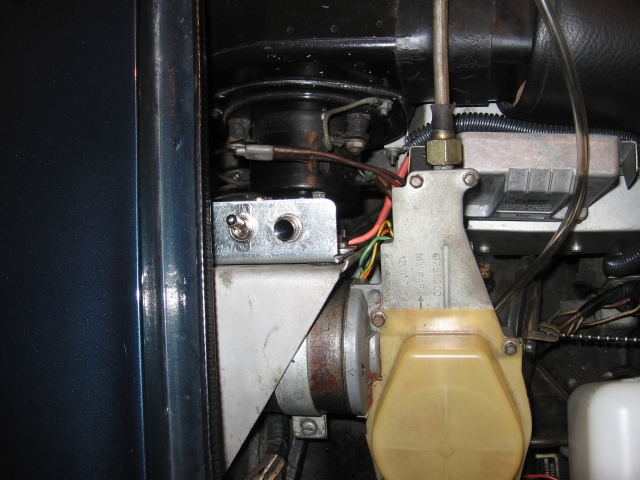 | ||
Robert Noel Reddington Grand Master Username: bob_uk Post Number: 937 Registered: 5-2015 |
My car being right drive has the wiper on the other side, at first I got confused. Good photos. I like the toggle switch, functional and robust. Does the car start in gear if this switch is used. If the switch works every time then I reckon the relay for the starter solenoid is defective. The Lucas wiring code is white with red tracer goes from ignition switch to starter solenoid coil windings ( the windings that operate the starter solenoid) Normally there is no relay betwix the solenoid and the ignition switch, the ignition switch being man enough to take the amps. But because the Shadow has an auto box, the auto box starter safety switch is a micro switch which isn't man enough to take the amps of the solenoid coil. So relay is used so only the amps of the relay coil go through the mircoswitches, which is milliamperes. 100ma I think. Which brings me to the micro switch in the column. The pivot for the gear change arm can wear a tad. Which makes the operation of switch erratic. If the arm is wiggled be around whilst holding key in start position and the starter works or the starter is working and wiggling the gear change arm makes the starter stop then there's yer problem. The switch may be adjusted by tweaking the bracket, maybe there is an adjustment by loosing the screws and reposition. Relays are very reliable and tend to fail completely and not sometimes work. Sometimes working is a bad connection most likely, earths seem to be the favourite. The wiring to the relay for the starter will have white/red, black and depending how RR wired the car, brown or plain white. Brown means the circuit is live and not controlled by the ignition. White means the circuit is only live when the the ignition is on. White is the most likely, because it keeps the live all the time circuits to a minimum for safety sake. White based wires in the Lucas colour code denotes wires that are estential for the engine to run. These are fuel pumps, ignition coil, ballast and oil presure switch/ low oil pressure fuel pump relay, and starter circuit. Because the Shadow has the auto choke stuff, the stuff is also white based. Because the temp gauge is not estential, the wire colour is green based, green denotes that the circuit is ignition controlled like indicators and not estential for the engine to run. Purple wire are live all the time fuse protected, example interior lights. If the horns work with out ignition on the wires are purple based if the horns only work with ignition on then the wires are green based. The Lucas colour code is of the web, and once one has got to grips with the designers logic, repair of the Shadow system is very much easier. The logic is quite good and easy to understand. Such as any red based wire is associated with the side lights. Any blue based wire is associated with the head lamps and dip. ( blue white is main beam and blue red is dip beam). When a device is switched via earth side rather than positive side, because the Lucas code is black means earth. The tracer on the wire will be black. Example: the head lamp flash works by earthing the coil on a relay, because it's headlights the wire is blue based and the tracer is black for earth side. Because horn switches are generally fitted to earth side one of the wires will have a black tracer. And so on. If the solenoid is fault it can be rebuilt DIY. Sealer covers the screws and I believe a soldered joint has to be released. The studs for the big fat wires are copper these can filed up. Across the bottom of the studs is a piece or coope that the solenoid pushes against the bottom of the studs again this can be filed up. If the bits are burnt away and eroded then copper bolts are available from nut and bolt stores. Use brass nuts and washers. The bit for the solenoid to push is a simple bit to make on the bench. In the workshop manual hopefully is the resistance value of the solenoid coil which is connected to the small spade terminal and the armature windings. If the resistance is correct then we can assume the coil is serviceable. If the coil isn't serviceable then new solenoid are available and it's probably used on a range of Lucas starters so should be easy to obtain at a reasonable price from an auto electrician who does rotating car electrical machines. When the solenoid is energised because it is at first in series with the armature the starter turns slowly to aid engagement with the ring gear. If you are not sure about EXACTLY how the starter works it is worth reading up on the Internet. I often find that some people version on how something works sounds right until closely examines the versions then one realises the version is incomplete. The bit often missed out is the holding voltage of the solenoid. Hope I haven't offended any body I don't mean to.😊 | ||
Geoff Wootton Grand Master Username: dounraey Post Number: 1140 Registered: 5-2012 |
Hi Bob Yes, the car will start in gear, which is why I mentioned the safety hazard and why the switch is temporary. The toggle switch is to prevent the engine cranking if the starter button is accidentally pressed. There is an inline 20A fuse just below the switches on the other side of the bracket. On the two occasions I have used it I made absolutely sure the gear selector was in P and the handbrake fully on (the handbrake holds my car at idle). However, on the plus side I really like the insurance this additional starter button gives me. The first time the clicking fault re-appeared I was 40 miles from home. It took a full 15 mins before the engine eventually cranked. I was getting near to calling a tow truck. Given that the wiring on these cars is 40 years old, I am thinking of fitting a permanent "auxiliary" starter button inside the car. In that position it would be safe, as you would need to be in the drivers seat to operate it. I am thinking of using an ignition switch located just behind the ashtray (denoted by the red circle) and keeping the key permanently in the glovebox. Alternatively, a push button switch in the deep well beneath the ashtray. 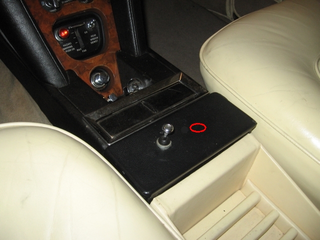 I am hoping I can just remove the black cover, behind the ashtray to gain access. If you know how to do this I would appreciate the info. Also, since your car is also a 74 model, do you know where the starter relay is located on your car. Geoff | ||
Geoff Wootton Grand Master Username: dounraey Post Number: 1141 Registered: 5-2012 |
BTW - thanks for the Lucas colour code info. Also, I have on many occasions tried wiggling the gear selector lever, but there does not appear to be any correlation. | ||
Geoff Wootton Grand Master Username: dounraey Post Number: 1144 Registered: 5-2012 |
I am still trying to find the location of the starter relay. On my car there are 3 relays on the left side bulkhead close to the washer bottle. The first is bolted to a bracket very close to the bulkhead and the other two to the bracket that holds the washer bottle, forward of the bulkhead. This is normally the location of the starter relay. However I have totally disconnected all of these three relays and none is the starter relay. The engine still cranks with all three completely disconnected. I noticed there are two small bolts on the front cover of the relay box. These are sized and spaced exactly as would be the case if they held a relay, possibly missing from my car. It occured to me the relay could be on the other side of the relay box front cover. I removed the cover, but no joy. No relay. I put the champagne back in the fridge. My car is a 1974 SY1. If you have a "series 1" could you take a quick look and let me know if there is a relay located on the relay box cover, just below and behind the bellows. The picture below shows the relay box after I had removed the wiper motor and bellows. The two arrowed bolts do nothing on my car. On the other side of the cover there are just two nuts. If the relay is bolted to the cover on your car, it should be easily visible. 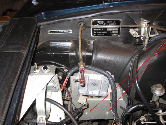 I have of course searched the forum and workshop manual and can find no picture to confirm or deny that this is the location of the starter relay, which appears to be missing on my car. I'd be really grateful for any help. Geoff | ||
Bob Reynolds Grand Master Username: bobreynolds Post Number: 374 Registered: 8-2012 |
Here is the Starter Relay on my 1975 Shadow (in the centre of the photo): 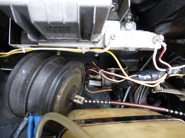 You can see it is connected to the ballast resistor just above it (not the original location for the ballast resistor) And here is the Choke Relay: 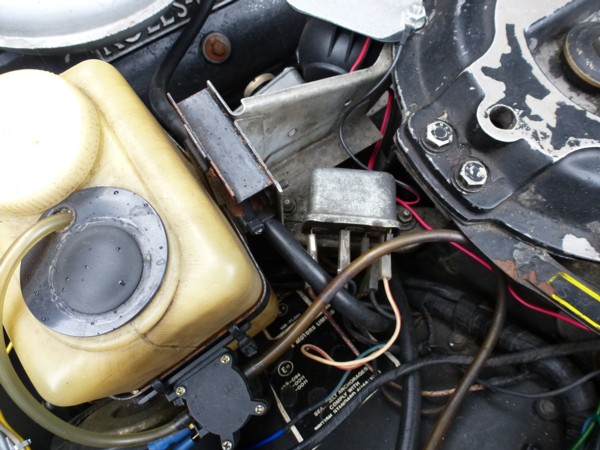 | ||
Jeff Young Prolific User Username: jeyjey Post Number: 238 Registered: 10-2010 |
Hi Geoff, Is this one of the relays you tried disconnecting? 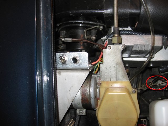 Cheers, Jeff. | ||
Geoff Wootton Grand Master Username: dounraey Post Number: 1145 Registered: 5-2012 |
Bob - I really appreciate your putting up these photos. It is really helpful. I can see on your car the two bolts that I referred to (on the relay box front cover) are also not used to hold a relay, so this question has now been answered. It's also really helpful that you have specifically pointed out the starter and choke relays. They are the same on my car. So the fact the engine on my car still cranks when the starter relay is completely disconnected means there must be a wiring issue. Maybe a previous owner has jumped the relay and taped the bodge into the loom. I will now get to work with a meter and try and figure out what is happening. Thanks again for your help. Jeff - That is the approximate location of the starter relay, but it is currently removed from my car. The picture shows some of the loose wires, partially obscured by the bellows. Thanks for your reply. Geoff | ||
Jeff Young Prolific User Username: jeyjey Post Number: 239 Registered: 10-2010 |
Geoff, Do you mean it was removed after you took that picture, or before? Because there does appear to be a relay in that picture inside the red circle, under the wires. (It's positioned vertically, with the connectors facing toward the wiper motor.) Cheers, Jeff. | ||
Geoff Wootton Grand Master Username: dounraey Post Number: 1146 Registered: 5-2012 |
Jeff I do apologize. I must have taken the photo before I removed the starter relay. I have now resolved the issue. The starter relay has been bypassed. I have found the offending wire. It has obviously been run from one of the cutout switches as the suppression of engine cranking in D or R has always worked. I've said this before, but I really wish people would not bodge these cars. If they can't afford to run them, they shouldn't buy them. A new starter relay is just 50 quid and will last for another 40 years. Just as good, if you are not too concerned about originality, is a Chevy relay at less than 10 quid. Hot-wiring means all of the terminals and connectors have been stressed by an amperage the circuits were not designed for. I just don't get it. I suppose on the plus side I have only ever come across one other bodge on my car, which was a bolt used in place of the correct adjuster on the brake light switch. This would have cost the idiot who bodged it just 15 quid to replace. Sorry for the rant - I'm expecting more issues now that I know the starter relay has been jumped. Thanks again for the help. Geoff | ||
Brian Vogel Grand Master Username: guyslp Post Number: 1867 Registered: 6-2009 |
Geoff, Not that it helps you, and I feel your pain, but one also has to consider that these cars have had long lives and have often been in areas where the people who are working on them had no reference material at all. The starter relay in these cars is quite standard across makes as far as specs goes and it didn't take much effort to find a low cost but fully functional equivalent (even though mine is still working fine). I wish more mechanics "in the hinterlands" would spend more time doing this than actually inventing work-arounds that are potentially damaging and hard to decipher decades later. Of course, now that I say the above, we're well into the internet age. When a lot of these bodges were done we weren't, and that makes a huge difference as far as ability to research goes. I don't know of anyone who hasn't resorted to, "Any old port in a storm," when the storm is big enough. Brian | ||
Vladimir Ivanovich Kirillov Grand Master Username: soviet Post Number: 451 Registered: 2-2013 |
Before everybody gets deep into their well thought out electrical theories I would point out that I have seen mechanics and car electrics people behave quite insanely due to the frustrations involved in locating and repairing electrical faults. As for my own experience even after forty plus years when it comes to electrical diagnosis I still feel intimidated and have feelings off nasty uncertainty until the grotesque little mongrel electrical gremlin is found and slain. So if any of you start to feel insane while you are doing electrical repairs just remember its normal even if you did bite the head off your wife's pet budgie in the process. . | ||
Robert Noel Reddington Grand Master Username: bob_uk Post Number: 940 Registered: 5-2015 |
The relay if faulty can be replaced with a modern 4 pin relay. They cost about �5. 20 amp should be enough 30 amp also available. If one wishes to keep the orginal look then a flatter vesion of this relay is available. Sometimes called a mini relay. This might fit inside the old case. Also the relay comes apart and maybe repairable The original type of relay is still available. | ||
Geoff Wootton Grand Master Username: dounraey Post Number: 1147 Registered: 5-2012 |
Brian - Thanks for the sympathetic words. I think what irked me was the certain knowledge replacing the starter relay is not going to cure the clicking starter fault, since it was not connected in the first place. Whether the lower amperage through the switches and connectors improves or makes things worse, when I've re-introduced the starter relay, I am yet to find out. You raise a very interesting point. It is so easy to take the internet for granted and forget that even just 15 years ago there would have been very little documentation and no forum or Tee-One help available. At that time a RR workshop manual cost about 400 pounds. I remember looking at a photo of a Cloud, beyond restoration, in Tee One topics with Bill's annotation of "if only the manuals had been available" (I paraphrase). So I absolutely agree with your view. However, there will be no excuse for bodging Phantoms and Ghosts in 20 years time, when they hit the enthusiast market. Vladimir - I have now returned to sanity and am currently gluing my hair back on and repairing the dents in the bodywork. Bob - cheers for the advice. Geoff | ||
Robert Noel Reddington Grand Master Username: bob_uk Post Number: 945 Registered: 5-2015 |
To get your head around car electrics. Cars have circuits that are on or off. Except gauges, fans and dash dimmer. The wiper is also an on or off circuit which depends on what speed selected. This means that most of the circuit is either live or dead. No varying voltages it's either 12v or nothing. ( 12v nominal ). Typical circuit Volts via a fuse go to a switch. Volts when switch is on go to light bulb or other device. The device must have an earth to work ( Lucas code is black for earth ) OR Volts go direct via fuse to the bulb or other device. The earth for the device goes to switch. ( this wire will have a colour with a black tracer as per Lucas code ) Other side of switch goes to earth. ( this wire will be all black ). Test lamps. These are very very very very useful. For testing non electronic stuff a test lamp is better than a digital multimeter. The test lamp will put a load on the system which if used on electronics can pop a transistor of something. A digital meter is non invasive and does not load the circuit. If a digital meter is connected to a 6w light bulb and the other side of that light bulb is connected to 12v. The meter will read 12v. If a test lamp is used then depending on what wattage the test lamp is the bulb being checked will light. If the test lamp is 21w then the test lamp will glow dimly and the 6w bulb being checked will be bright. If the test lamp being used is 3w then the test lamp will glow bright and the bulb being tested will be half dim. If the bulb being tested is 21w then a 21w test lamp and bulb being tested will be half bright. This happens because the test lamp is in series with the bulb being tested. Suspose the test lamp or bulb being tested does not light. The test lamp earth could be bad. The bulb could be blown. The circuit is dead. The fuse is blown. The switch is faulty. Could be more than one. Go to fuse test with lamp test both sides both sides should light the test lamp. Go to switch one Sid on switch should be 12v. Go to other side of switch when on should be 12v. Go to device one side should 12v. Earth test lamp using device earth. If the device is a heavy amp user such as fans then use 21w test lamp. If side lights then either 3w or 21w. The halogen test lamp if used on side lights may blow the fuse. The load that a test lamp puts on a circuit shows up dodgy connections that a Digital meter won't show because the connection is good enough for no load but as soon as the load goes on the connection goes down. Earths are often like this it looks ok but it isn't. I have 3 test lamps. 3w 21w these get hot enough to burn fingers and trim. 60w Halogen bulb in box because they get serious frigging hot. Most times when using a test lamp, I earth off of door catch bits on the B post. This is for easy checking of circuits In the cold dark days of despair of the electrics not working the heat of the halogen helps keep you sane that electricity does actually. The Lucas colour code is on the web somewhere google it. Use a smear of petroleum jelly on any connection that you plug in. I read that Vaseline when used on battery terminals, it seals where the battery post comes through the case which is why it stops the post going furry. To clean battery posts and clamps. Simple boiling water and it magically disappears. A top SAFETY TIP is to disconnect the fat earth lead from the battery and connect between the fat earth lead and the battery a say 30 amp fuse. Should you cock up the fuse blows thus saving a burn up and maybe a total write off which happens more than one would think. If the wiring behind the dash got cooked it would cost lots of time and money to put right I suspose a second hand loom could be fitted but not me sir. I have a 20amp circuit breaker with wires and crocodile clips. If the starter motor is engaged the load will pop the breaker. So the battery will have to be connected properly to use the starter. Incidentally some of the older 240 vac house hold breakers also work at 12v because they were ampere sensitive only. Repairing fuses. The glass ones can be repaired by removing the brass end caps ( if they aren't brass then they have no business in a Rols-Royce ) the fuse wire is soldered to the end caps. The fuse wire goes through a small hole in each cap and is soldered which is how they are made. Or you can cheat and solder the fuse wire down the outside, bit naff though. In electricians hand books are the gauge and rating of fuse wire. Fuses blow due to amps not volts. So any voltage is the same. 10 amps is 10 amps from zero volts to mega millions volts. A source of fuse wire can be copper strands from an old bit of wire. If using copper the fuse wire is best inside the glass tube of the fuse because copper can splatter when it blows. But not really very much splatter, OK on cars but not near delicate electronics such as the stereo at home. Note that fuse wire is different stuff from copper but the gauges and ratings are similar and the accuracy is not that important. Because say fusing a 21w light bulb. Which is about 1.8 amps. Allow a bit for volt surge and the resistance of the bulb being low because it's god a cold filament. Call it 3 amps or 4 or 5. The object is to protect the wiring and the switch. The wiring used for a 21w bulb is heavy enough to take 10 amps and may be a bit more. The switch is 10amps so long before any damage the fuse has popped. Me being me I once put too finer wire in a fuse and it actually glowed for about half a second and blew. If I had sucked the air out I would have a light bulb. Which brings me to a tip. If a fuse continual blows then the circuit is hard to fast because it's dead. If a bulb is connected across the fuse holder then the short will light the bulb. When the bulb goes out the short is found. But remember that the fuse is in series with the circuit not parallel. The fuse on the Shadow are an odd size and not readily available. Smashing fuse board. Other makers should take note. So as one can see test lamps are very ( many verys as you like ) useful and a boot tool kit must. Along with the gaffer tape. Test lamps can be made by simply soldering the wires to the bulb. Saw. A very neat test lamp kit with plug on crocodile clips and more stuff for every eventually. Unfortunately the owner didn't know how to use the kit and charged me �30 frigging quid to repair a Golf. I had to fix it myself. To test a wire that has no easy access terminal. Use a needle or the sharp pointed test lamp probe though the insulation. A bit of heat and a rub with a finger will recover the very very small hole. Obviously the load is limited but enough for 3w or 21w test lamp home made jobbies. I still use a digital meter on the Shadow for checking voltage drop because it's the only way when one is working down to 0.01v. Battery checking needs to be that accurate. Saying just over or under 12v is useless. The facts Mam and nothing but the facts. As an exercise. Try drawing a car electrical system for something simple like a Austin Mini. Use colour because it's again Lucas code. It will give you a better grasp of how it all works. The original diagram is on the net somewhere. All Brit cars of this era except Ford and maybe Vauxhall used the Lucas code. Ford once used the Lucas code except they deleted the fuse box. The cars had no fuses apart from a fusible link !!!!. A fusible link. This is an intentially a thinner than normal wire. The thin wire is not long before it connects to the normal size wire. The fusible link is usually connected between the main power feed from the starter or battery that works the rest of the electrics. The idea is that should the car short out the link melts but the link has to be of a higher amps because the whole load and battery charging is going through the link. This was ok ish when the car didn't have a lot of electrical load say 30 amp plus with Dynamo running the back and forth load on the Iink would be lower. But when it comes to complicated heavy loads such as the Shadow then separate fuses are very very essential. Circuit breakers. These sound good but there is a danger. It is possible to get a short on say a 10 amp breaker that is just the right amount of Amps to cause the points to weld together and not work causing further heat until the points are well and truly welded shut. This takes milli seconds to happen and the operator won't know until the dreaded smoke. This means that fuses before the breaker are needed. However some breakers have an internal fuse. The breaker is 10amp and the fuse is 11amp. But the fuse can't be repairer but there again would you repair a fuse in a faulty breaker. No of course not. In my head is a wiring diagram for cars, buses, trucks,l radios, petrol tankers, my house and motor bikes. The rest I sus out I go. Often I can't figure it out then the explosion in my brain happens and the fault reason comes flooding in. Once the fault is known the rest is easy peasy. Money permitting. But usually it's pennies. | ||
Geoff Wootton Grand Master Username: dounraey Post Number: 1149 Registered: 5-2012 |
Hi Bob Here's one to tax your brain. What is the mechanism for reversing the wiper motor, when you switch the wipers off. Internally there are two switches in the actual motor. One detects each revolution of the main gearwheel and the other is used to switch the motor off when it is in reverse. This second switch can be adjusted to correctly park the wipers "off" screen. In addition, there are two control units. One for the wash/wipe function and the other for intermittent wipe. I don't believe either has the additional functionality to reverse the motor, so we can rule them out as far as this problem is concerned. So, when you turn off your wipers, they continue wiping until the on screen park position is reached and then the motor goes into reverse. What is the mechanism that makes this happen? Obviously, the polarity of the wires going to the motor must be reversed in some way. But how. The wiper system obviously knows the wiper switch has been turned off and the on screen park position has been reached, but what happens then. Where's the intelligence in the system that causes the motor to go into reverse. There are no microprocessors on these cars. If you can figure that one out, not only would I be interested to hear, but the next time I am in the UK I will personally deliver a bottle of Jack Daniels to your door. Geoff | ||
richard george yeaman Grand Master Username: richyrich Post Number: 480 Registered: 4-2012 |
Hi Geoff your last post would have been a good candidate to go in the thread headed Quiz the man who thought it all out probably ended up in a padded cell (poor Bob) Richard. | ||
Jeff Young Prolific User Username: jeyjey Post Number: 240 Registered: 10-2010 |
Wiper relays 122 and 130 reverse the power feed to the motor (each controls one side of the motor feed). The coil of 122 is controlled by the wiper switch, but it is also latched by the park-on-screen switch in the motor (so it keeps the wipers going till they've completed their stroke even after the wipers are switched off). The coil of 130 is fed through the "off" contacts of 122 and the park-off-screen switch in the motor, so when 122 switches off it turns 130 on. This runs the wipers in reverse until the park-off-screen switch trips. Cheers, Jeff. | ||
Geoff Wootton Grand Master Username: dounraey Post Number: 1151 Registered: 5-2012 |
Jeff Many thanks for that excellent explanation. My car is an SY1 so relays 122, 130 and 131 are not in the sensible position shown in the SY2 workshop manual. I can hear one of them click from under the top roll when the wipers are turned on, so I suspect this is where all three are located, along with the control units. Hopefully this is just going to be a case of pulling off the top roll and testing/replacing the relays. It will be nice to have fancy wipers on my car again. I hope you don't mind my putting a copy of what you have written in the thread http://au.rrforums.net/forum/messages/17001/15158.html This thread contains a lot of great information and also an excellent explanation of the mechanical operation of the wiper unit, by Bob Reynolds. Geoff | ||
Jeff Young Prolific User Username: jeyjey Post Number: 241 Registered: 10-2010 |
No worries, Geoff. BTW, if you do find a dodgy relay, it's worth trying to refresh it. I've run across 3 faults so far: 1) pitted and/or arc splattered contacts: fold a piece of 400 or 600 grit sandpaper so there is abrasive on both outside faces, place it between the contacts, close the contacts with your finger and draw the sandpaper back and forth until the contacts are burnished (stay away from the fold as the sandpaper will be thicker there, and blow all the grit out before re-assembling the relay) 2) off-square contacts: a bit of work with some needle-nose pliers followed by sanding (as above) will usually sort this out 3) loose joint where one of the spades is riveted to the board: re-crimp rivet and solder My fan and compressor relay exhibited all 3 faults, but most of them only had 1. At some point I'm sure I'll come across a burned out coil, but I haven't yet. Cheers, Jeff. | ||
Geoff Wootton Grand Master Username: dounraey Post Number: 1155 Registered: 5-2012 |
Hi Jeff I did test the starter relay on my car. This is the one I eventually discovered had been bypassed by a previous owner, who had hotwired the trigger wire directly to the starter solenoid. It was completely dead, which explains why he bodged the system. I did notice however there were a few small sparks as I touched the +12 wire on the coil connector of the relay, indicating the coil was not open circuit. So it looks like it may be one of the repairable faults you mention. Geoff | ||
Robert Noel Reddington Grand Master Username: bob_uk Post Number: 949 Registered: 5-2015 |
Geoff you will notice that a lot of faults are down to dodgy connections like rivets that hold male spades to devices that aren't soldered and corrode a bit and go dodgy. This is because we weren't ment to using 40 plus year old cars. The actuall wire between the various terminals everywhere are the most reliable bit of the system. It is very rare to find a wire that is broken inside the insulation. But very common for the wire to give trouble or break off at the terminal. The only wires that I have seen break was because of continual movement and I have only seen a very small amount. Dealing with copper that has gone green or has a brown dull patina like domestic copper water pipe does. The copper must be bright and shinny. So just like a plumber would if soldering older copper pipe the copper is cleaned. I do this by spreading the strands out in a fan shape and stroke the strands with 80 grit abrasive paper. Do both sides of the fan. Rest the fan on a bit of metal. A small scraper will do as a rest. Then close the fan twist and smear with plumbers resin flux and then tin with electrician multi core solder which has flux in it. Crimp or solder. The crimp is a mechanical connection only which if done correctly is very good but a special crimping tool is required, the �3 ones are no good. The correct ones click off at a certain pressure and leave a number impressed in the plastic bit. My ones cost �80 about 30 years ago. Solder is very good for DIY. Solder does have resistance though but the ohms are so low it's a dead short. If the wire gets hot enough to melt the solder the insulation will have melted first. Joining wires and fitting terminals. Bare back insulation with stripping pliers about 10 mm is usual. Twist and tin the stands with solder. Insert the wire in to the connector crimp gently with normal pliers if necessary. And then solder the terminal on by heating with a 25w soldering iron. Feed a bit of solder into the joint and it's a good un. If using those spades with blue red or yellow hard plastic sleeves I pull the sleeves off and discard, I use heat shrink instead. Remembering of course to fit the heat shrink on before the joint is made. Recently on car SOS. Tim Shaw said that to join two wires together it is not necessary to twist the strands together. This is wrong. The best way is to fan out both wires and put the fans together in line and then twist the strands around each other. This is called a married electrical joint. Once soldered and heat shrunk the joint has more mechanical strength than the parent wires. Also it's virtually invisible. Joining a wire into an existing circuit. Typically this is used on tow bar electrics. I have seen the mess the professionals make of the wiring. Sotch locks every where and in a couple of years tow bar electrical problems. Two ways. Cut the wire and join in the third wire and solder and then heat shrink. Or don't cut the wire but bare back a bit of insulation. Then solder the third wire. Poke the third wire though the original strands and twist. But the heat shrink cut be used so it's insulation tape only. Or gaffer tape. Never sellotape or masking tape except to get home. Note wipe off excess resin and smear with petroleum jelly before heat shrinking. | ||
Bob Reynolds Grand Master Username: bobreynolds Post Number: 377 Registered: 8-2012 |
"The crimp is a mechanical connection only which if done correctly is very good but a special crimping tool is required, the �3 ones are no good. The correct ones click off at a certain pressure and leave a number impressed in the plastic bit." Correct. And different connectors need different crimping pliers, and ideally these should be made by the same manufacturer that made the connector. So it gets very expensive! Simply squeezing with pliers doesn't do a lasting job. Best to crimp then solder. | ||
David Gore Moderator Username: david_gore Post Number: 1964 Registered: 4-2003 |
High quality cutting, crimping and swaging tools for cable and wire are readily available from suppliers to the electrical contracting trade. I have a set of German tools which have had a lot of use and producing excellent results. More expensive than the Asian alternatives but worth the extra expense given their reliability and capabilities. I have not found any problems using these on different brands of connectors - the only problems are associated with inferior brands being more liable to break when being attached to lugs/screw terminals/connectors during final assembly. | ||
Geoff Wootton Grand Master Username: dounraey Post Number: 1156 Registered: 5-2012 |
Does anyone know where to buy connectors that can be soldered, with the detachable insulating covers? All of our local stores now only supply crimping connectors. Geoff | ||
Paul Yorke Grand Master Username: paul_yorke Post Number: 1502 Registered: 6-2006 |
Hi Geoff, Maplin, Holden, Ebay. Google LUCAR SOlder probably. To use them you need another crimping tool again, with an operation to close the crimp slightly, and then a second to fold the crimp in on itself. http://www.ebay.co.uk/itm/Ratcheting-Crimping-Tool-for-Open-Uninsulated-Terminals-/310128447530?hash=item483518902a:m:mG0fNLJU6KsGyPdA8oWmpBQ A good crimper and insulated terminals do a good job bat are annoying with the colours. Black SHarpies come in handy. | ||
Robert Noel Reddington Grand Master Username: bob_uk Post Number: 952 Registered: 5-2015 |
A neat, good looking and reliable joint is important on a Rolls-Royce. Shops like Halfords sell those little blister packs with say 4 connectors in it at a grossly inflated price. �0.99 Order them in 100s and they are very cheap. Don't forget to get heat shrink stuff in different colours. Heat shrink goes as big as 50 mm. So should you dislike black water hoses you can have them coloured with heat shrink it may give extra strength. But of course no one in their right mind would use heat shrink to repair a hose would they, at least I hope not. The spades can be brought in a roll form. The invidual spades just snap off the adjoining spade. At the fuzz garage we had a reel of a 10,000. They were so cheap that I used them with gay abandon. Those light bars used a lot. Note the only materials I will accept when doing auto Sparks is brass for the connectors and terminals and copper for the wire. On marine stuff and fuel tankers I use copper wire that is tinned. I think the fly guys only use tinned copper wire as well. Note that some connector are dull silver coloured. I think these are brass plated with tin. A quick file will show what's underneath. It ain't brass then do not use on a Rolls-Royce or any other vehicle. Except Fords because brass connectors will increase the scrap value and we can't have that can we. I never understood why the villains used Transits as getaway. If I had just robbed a bank, I would want the van to start first time and not breakdown before I escaped the fuzz in 3.4 S type Jags and P6b Rover V8s. A soldering iron will damage trim and insulation of other wiring within half a second. So be carefull. I have also a small gas soldering iron which is frigging brilliant. If the copper bit is unscrewed the flame is hot enough to solder 15mm O/D domestic copper water pipe. As a stand for an electric iron 25w is ideal and only about �10 and will last for years. Solon is a good make in general uk. I use a old tin can which is half full of set plaster to give the stand weight. Makes sure that the electric soldering iron lead is kept clear of the iron and that the lead has slack, soldering can be delicate work. This doesn't apply to cars. Never ever attempt to solder any thing that is still plug in the mains, because the soldering iron has an earth and it will short out what ever you are attempting to solder. Seen that mistake made. Dangerous. About 10 years ago my cruise control malfunctioned. So I posted this forum and Dave Gore sent me the wiring diagram. I took the speed stat off and checked it checked for continuity etc and found nothing wrong. So I gave up. Then I realised I had not be actually turning it on even though I had had the the car 17 years at the time and using the cruise control successfully. The moral is before one decides something is malfunctioning check that the stupid operator is operating the machine properly. Doh. Why 99p and not �1. It's because it's to easy for the cashier to pocket the pound. The till has to be opened to give the change, thus recording a transaction. | ||
Bob Reynolds Grand Master Username: bobreynolds Post Number: 379 Registered: 8-2012 |
"Does anyone know where to buy connectors that can be soldered, with the detachable insulating covers? All of our local stores now only supply crimping connectors." Use ordinary crimping connectors. Crimp first and then solder. (The crimping also holds the wire in place while you solder.)  "I never understood why the villains used Transits as getaway." Inconspicuous? (I'm guessing, of course)  | ||
Vladimir Ivanovich Kirillov Grand Master Username: soviet Post Number: 456 Registered: 2-2013 |
Bob is dead right about transits. Neddy Smith did many armed holdups in Sydney using rented panel trucks simply because of them being inconspicuous. Its all in his book along with the countless payments to a one time incredibly corrupt police force. | ||
Geoff Wootton Grand Master Username: dounraey Post Number: 1157 Registered: 5-2012 |
Use ordinary crimping connectors. Crimp first and then solder. (The crimping also holds the wire in place while you solder.) The problem here is you cannot buy the connectors with the removable insulation. 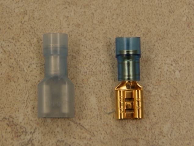 I know I could break the insulation off, solder the joint after first crimping it and then use heat shrink to cover it, however, I prefer the more professional look of the insulating cover. I was surprised at the price of the crimping tool Paul pointed to on ebay. 29 pounds for a ratcheting type is cheap. My crimping pliers are good quality, but not the professional ratcheting type. Thinking about it, maybe I should just abandon my pedantry and use the crimp,solder,heat-shrink method. At least the connectors are easily available. Geoff | ||
David Gore Moderator Username: david_gore Post Number: 1966 Registered: 4-2003 |
Sometimes but not always, you can remove the insulator after softening it by heating it with a hair dryer. Only downside is you have to use a sleeve made from clear heat shrink tube to securely locate the insulator after sliding it back into position over the terminal after soldering using the hairdryer to soften the insulator if necessary then installing the heat shrink sleeve over the insulator and shrinking it into place. As an aside, I find the above type of terminal is invariably of better quality and more robust construction than the terminals with removable sleeves. | ||
Kelly Opfar Frequent User Username: kelly_opfar Post Number: 55 Registered: 7-2004 |
These guys have all the correct terminals, wires and tools for our cars. http://www.britishwiring.com/ I used their products to repair and restore the wiring harnesses on SRE24700. They even have the correct rigid white spade terminal covers that are all over the engine bay: http://www.britishwiring.com/1-4-Spade-Rigid-Terminal-Cover-p/c995.htm | ||
Geoff Wootton Grand Master Username: dounraey Post Number: 1158 Registered: 5-2012 |
Kelly Many thanks for the link. In fact I bought some bullet connectors from them a couple of years ago but just could not remember the name of the website. Problem solved. BTW: That copy of "From the Shadow's Corner" you pointed me to, on ebay, arrived after a week. Mint condition and a great addition to my documentation. Thanks again. Regards Geoff | ||
Robert Noel Reddington Grand Master Username: bob_uk Post Number: 957 Registered: 5-2015 |
The sleeves on the red blue and yellow connectors simple come off with a twist and pull with pliers. Heat shrinking the whole connector does look professional and is used on new high end cars. Probably the BMW RRs have heat shrunk connectors. This method is high quality and if an electrical did this on my car I would happily accept the Job. If Insaw insulation tape I would knock the job back to him. The separate plastic covers are obviously good but heat shrink does add mechanical strength to the connector, not that one is going to use the wiring as a tow rope. But the advantage is still there and my money on the heat shrink. Also the slenderness of heat shrink looks better to me, and I can coloured code stuff which may have wires all black or red or what ever. Geoff, Me old mucker, I think you are making too much of a perfectly straight forward connector thing and worrying too much about it. So have a go on some bits of wiring. Then hang the wiring up with a weight on the end to test the connector. KGo mad and test to destruction note the weight applied. Use a bucket and add a litre at a time, a litre of water weighs 1 kilo gram or 2.2 pounds. | ||
Geoff Wootton Grand Master Username: dounraey Post Number: 1160 Registered: 5-2012 |
Hi Bob I do accept that I am probably a bit OCD-ish about crimped connectors. In fact the ones I used on the upgrade to my rear window motors have performed perfectly for two years. But here's the thing; there are certain connectors that I do not want to risk failing. I want the best joint possible. The connector to the starter motor solenoid is one example. Those to the ignition coil another i.e. any connector that causes me, if it fails, to have to call a tow truck. I have read several times in this forum that soldered joints are by far the best. Given that Britishwiring.com sell the precise connectors I require, it's a no-brainer. Geoff |