| Author | Message | ||
Vladimir Ivanovich Kirillov Grand Master Username: soviet Post Number: 423 Registered: 2-2013 |
Does anybody know the specific dimensions of a 1976 Rolls Royce engine cylinder liner tool? If so please post it as I want to make one up for the Camargue. I have slight pitting in one cylinder liner in the upper cylinder area where the piston rings move and I am yet to decide whether to go the entire task and remove all the liners before rebuilding the engine. So it would be nice to have one already made up and ready to go. Thanks | ||
Robert Noel Reddington Grand Master Username: bob_uk Post Number: 873 Registered: 5-2015 |
Vladimir, The design is simple. A Tube that the liner fits into slightly longer than the liner. One end of the tube is a stepped plug. A second stepped plug that fits the bottom of the liner with an out side diameter that slightly smaller than the outside diameter of the bottom of the liner. Both stepped plugs have a central hole. For draw bolt. M24 studding brass washers 2 under each nut. By using a big thread one does have to worry too much about the strength of the draw bolt. Both stepped plugs need to be 25mm thick due to the bending force imposed by the draw bolt. The tube walls will be under compression and therefore 10 mm thick wall is enough. Depends on what's lying around scrap at the machine shop. Simple lathe job. 0.25mm or 10 thou tolerance. The liners must be removed with the adjacent liner still fitted. Otherwise the bridge bit over the top of the main brgs will crack and scrap the block. So if A1 is removed the next one will be A3 leaving A2 and A4 to support the bridges. Heating the block. This is difficult and takes ages. On tee one topics Bill Coburn used electric radiators and blankets. One guy boiled the block in water. He said this softened the scale. Some have reported that the liners came out easy and it was no problem. A method for heating could be a simple bonfire with the block suspended over the fire. To fit heat block freeze liners. However before you pull the liner try a tool called a cylinder bore glaze buster. This is simply a flap wheel that has changeable emery cloth. The flaps are 6 inches long. Fits into drill chuck. Often at first sight bore damage as described seems really bad until it's cleaned up then it looks much better. The obvious concern is oil burning on that cylinder. If the pitting is above the oil control rings then only the compression rings pass over that area of the bore. So you will most likely get away with it. If the pitting is further down then it's a judgement call as to weather to change the liner or not. Because you have never seen or heard this engine running it makes judgement calls that much harder. In an ideal world it would be lots of new bits but it gets too expensive. If a small tv camera is available take the coolant drain plugs out and water pump then have a good look inside. The scale can distort the bottom of the liners causing the piston skirt to wear quick and piston slap. The scale can be removed with chemical and manually poked out. Check the weep holes any sign of leakage means liners out. It's the only chance you will get to fix the seals unless you are prepared to take the engine out and pay for another gasket set. Fit new rings as a matter of course. Crankshaft sludge trap. Fit new circlip after cleaning. Rolls Royce never expected that 40 years later some one would want to pull the liners. RR maybe thought 10 years at the most. Renault used wet liners for many years. These were a clearance fit in the block and only held in by the cylinder head and if the head was removed I would clamp the liners down with the head bolts and large washers so the engine could be turned without pushing a liner up. When rebuilding I used to fit a liner and piston set. Such an easy design to work on never had liner leaks. RR in their infinite wisdom made their design IMO to complicated. | ||
Paul Yorke Grand Master Username: paul_yorke Post Number: 1460 Registered: 6-2006 |
Hi, Sorry, I haven't got the sizes to hand, but I would say change the seals while you have the engine apart. The top end of the puller only needs to be about 5" high. Once the liner had moved that far it should come out the rest of the way pretty easily. | ||
Geoff Wootton Grand Master Username: dounraey Post Number: 1088 Registered: 5-2012 |
What is the advice on pulling the liners cold. I have heard from different sources there is no need to heat the block. Is this true, or is it a case of trying it cold first, then heating if the liners are stuck. It occurs to me that pulling them cold may work each time but might also result in a cracked block. Geoff | ||
Kelly Opfar Experienced User Username: kelly_opfar Post Number: 44 Registered: 7-2004 |
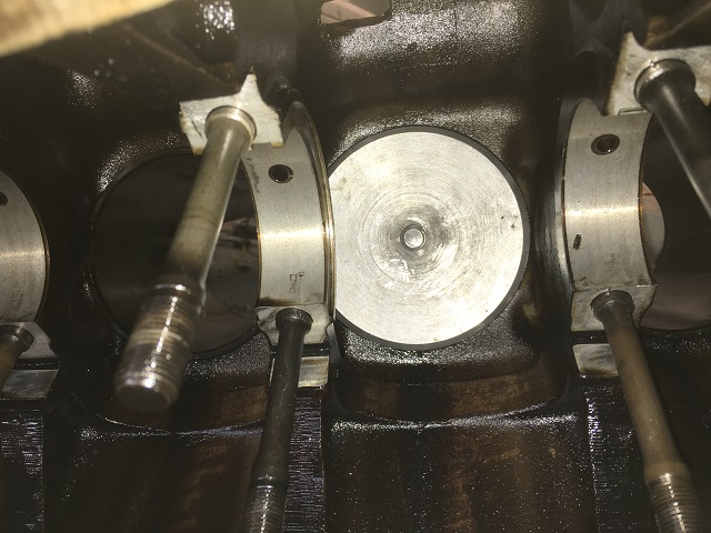
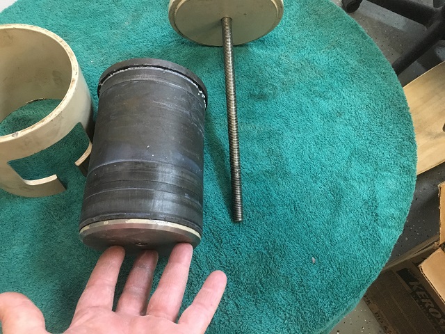
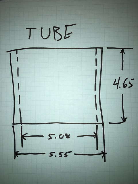
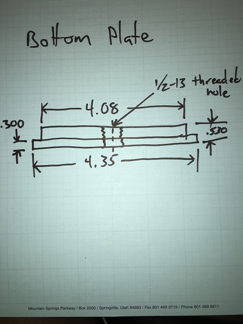
Here are a few pics of the puller I made with a couple of crude drawings that show the dimensions. The window in the tube allows for visuals so it can be placed correctly and provides a place to put in ice if wanted. The window can any size you like. If you leave the studs in the block, you will have to make a few cutouts for stud clearance. 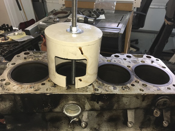 | ||
Kelly Opfar Experienced User Username: kelly_opfar Post Number: 45 Registered: 7-2004 |
 | ||
Kelly Opfar Experienced User Username: kelly_opfar Post Number: 46 Registered: 7-2004 |
 | ||
Kelly Opfar Experienced User Username: kelly_opfar Post Number: 47 Registered: 7-2004 |
 | ||
Kelly Opfar Experienced User Username: kelly_opfar Post Number: 48 Registered: 7-2004 |
 | ||
Kelly Opfar Experienced User Username: kelly_opfar Post Number: 49 Registered: 7-2004 |
 | ||
Kelly Opfar Experienced User Username: kelly_opfar Post Number: 50 Registered: 7-2004 |
 | ||
Geoff Wootton Grand Master Username: dounraey Post Number: 1089 Registered: 5-2012 |
Kelly Fabulous work here (as always). Thanks for sharing it. How did you cut the window in the tube? Geoff | ||
Vladimir Ivanovich Kirillov Grand Master Username: soviet Post Number: 426 Registered: 2-2013 |
Thanks for posting those photos and drawings Kelly as they will be of great help. I noticed you used a course thread for your pulley and I was going to use a much finer thread to give the puller more power having read that these liners can take quite a bit of pressure to remove. Can you add anything to the heating debate in relation to your own experience. If I am right from memory you are the gentleman who ventured into the dark world of removing all the studs from your block too with all types of accompanying drama - is that correct? | ||
Kelly Opfar Frequent User Username: kelly_opfar Post Number: 51 Registered: 7-2004 |
Geoff, the window was cut on mill probably with a 1/2" endmill. I made it several years ago. Vladimir, fine threads certainly offers more power pulling torque. I used 1/2"-13 because I had it. 1/2"-20 or 5/8-18" is harder to find at a local source in my area. Everything is available from McMaster-Carr. I pulled the liners out of the block on SRE24700 by putting the entire block on an engine stand in a large oven meant for powder coating at 250 degrees Fahrenheit. All the liners came out very easily that way. My block had no corrosion in the grooves and I had no issues. Cal West's book says the liners can be heated up with a propane torch with the puller in a tension position then filling the liner with ice. I am the poor sod that went through much grief pulling the studs. I recently recounted the trauma/drama on RollsRoyceForums.com under the Engine Removal thread. I am now in the process of rebuilding the engine from '80 Shadow II 41193. I no longer have access to the powder coating oven. I'm going to try Cal West's method. | ||
Robert Noel Reddington Grand Master Username: bob_uk Post Number: 877 Registered: 5-2015 |
Vladimir, I think a mere 1/2 inch thread size is a bit on the small side. I would use M24 and big spanners. A finer thread does indeed give more force for a given torque because the wedge of the thread or helix is a smaller angle. But a fine thread is more delicate due to thread depth. So plenty of grease and long spanners. Also if you take the headstock brgs out of a push bike, cone and cup and balls, and use them under the nuts it will help greatly with the friction between draw bar and plug. | ||
Geoff Wootton Grand Master Username: dounraey Post Number: 1090 Registered: 5-2012 |
Bob With all due respect, my guess is that if you are going to apply a force great enough to strip a 1/2 inch thread, then you are in "crack the block" territory. Geoff | ||
Randy Roberson Grand Master Username: wascator Post Number: 639 Registered: 5-2009 |
Amazingly clean liner exterior and block: it must have had reasonably good care over it's history. Rather than a threaded rod one might utilize a Porta-Power hydraulic cylinder with the open-center cylinder. No torque that way; nothing but pull. Also maybe one could build the puller so it was supported by the entire block face rather than just around the cylinder: spread the load, so to speak. Just ideas. I really enjoy these illustrated topics. thanks for sharing. | ||
Philip Sproston Experienced User Username: phil2025 Post Number: 23 Registered: 7-2006 |
Vladimir Look at TEE ONE Edition 86 page 1172.To heat use two burners on a BBQ with blankets heat to 150c. Will take 15 minutes | ||
Vladimir Ivanovich Kirillov Grand Master Username: soviet Post Number: 427 Registered: 2-2013 |
Bob your statement here has me most confused : "The liners must be removed with the adjacent liner still fitted. Otherwise the bridge bit over the top of the main brgs will crack and scrap the block. So if A1 is removed the next one will be A3 leaving A2 and A4 to support the bridges." If one removes all the liners down one side of the engine then when it comes to the other side of the engine you are not going to have any liners on the adjacent side of the engine to prevent the cracking. Are you saying you should remove all the liners down one side, then replace those liners with new orings and reheat to remove the liners on the other side of the engine. Would not the reheating of the block damage the new orings? | ||
Kelly Opfar Frequent User Username: kelly_opfar Post Number: 52 Registered: 7-2004 |
Vladimir, the procedure is to remove cylinders A2 and B2 first, then clean the liners and block bores of all nicks, corrosion and debris. Take the opportunity of having one liner out of each side to spray some penetrating oil around A1, A3, B1 and B3 as far as you can reach. Then lube the newly cleaned liners and slide them back in without sealing rings. They should push in by hand or be gently persuaded with a rubber mallet. They are not supposed to have an interference fit. If they don't go back in place with a reasonable amount of persuasion, something is amiss. Now that the 2's are back in place and offering support to the bridge, A1 and B1 can be extracted. Repeat the procedure for A3 and B3 - pull them, oil A4 and B4, clean everything, put them back in and extract the 4's. Then take the 2's and 3's back out and clean everything to your hearts content. Cal West says that the first liners on each side are the most difficult to extract and have the highest risk of damgage during extraction. Taking the 2's and 3's out first allows penetrating oil to do a little magic. | ||
ChristopherCarnley Unregistered guest Posted From: 5.80.21.202 |
Nicely explained Kelly, but Section E3 of the Workshop Manual indicates as small interference fit of the liner in the crankcase, and the whole of the procedure is explained in detail. (Message approved by david_gore) | ||
Kelly Opfar Frequent User Username: kelly_opfar Post Number: 53 Registered: 7-2004 |
Christopher, you Sir, are correct! The workshop manual says "Important - Do not attempt to fit a liner into a cold crankcase". On page 3838 of Cal West's book - From the Shadow's Corner - first paragraph, he says, "Before re-assembly, check each liner in its respective hole to be sure that it fits and can be installed and extracted by hand without the sealing rings in place." I think we should err on the side of caution and use a little heat to install and extract liners. | ||
Geoff Wootton Grand Master Username: dounraey Post Number: 1091 Registered: 5-2012 |
Kelly Thanks for all this information. Also the piece you wrote on extracting cylinder head studs on the other forum. So it appears heating the block for extracting the liners is mainly about breaking the seal between the liners and the block. When you mention Cal West's book, is this available for purchase? I have heard of Shadow's Corner and believe it to be part of the US RR owners club website. Is this true? I would quite like to read Cal's work. Would joining the US club give me access to it? Geoff | ||
Kelly Opfar Frequent User Username: kelly_opfar Post Number: 54 Registered: 7-2004 |
It is a spiral bound book that used to be available for purchase on the RROC online store for $20. I just looked through the store now and I don't see it. The book is made of excerpts from "The Flying Lady" in issues from '86 to '89. | ||
ChristopherCarnley Unregistered guest Posted From: 86.138.60.36 |
Part of the reason for heating apart from the plain fact that heating a metal with a hole in it expands the hole diameter, and preferentially with the aluminium alloy, is that the interference fit is not destroyed by scraping the bridge material away. The XK Jaguar valve guides are a plain tube, and so as not to have loose guides after straight "press" removal, the instruction is to drill out the guide hole until it, the guide,is very thin. (Message approved by david_gore) | ||
Paul Yorke Grand Master Username: paul_yorke Post Number: 1465 Registered: 6-2006 |
The interference fit is only to stop it wobbling around. Unlike valve guides which can move if the valve sticks, the liners are fixed in place so can not move if a piston seized. If very very serious corrosion build up is known to be present and may damage the block it is possible to bore down the liner, or machine a large diameter groove down one edge to try and relieve some pressure but, once again unlike valve guides, they are not a parallel tube. I would also say make a puller that fits inside the studs (with cut-outs) so you do not have to remove them. | ||
ChristopherCarnley Unregistered guest Posted From: 86.130.236.208 |
What about the R-R tapered valve guides? (Message approved by david_gore) | ||
Paul Yorke Grand Master Username: paul_yorke Post Number: 1467 Registered: 6-2006 |
"What about the R-R tapered valve guides?" What do you want to know about tapered valve guides? Maybe you should add a new topic? | ||
ChristopherCarnley Unregistered guest Posted From: 86.164.119.62 |
Paul, You introduced it, "once again unlike valve guides". (Message approved by david_gore) | ||
Paul Yorke Grand Master Username: paul_yorke Post Number: 1468 Registered: 6-2006 |
David Gore - Are two people posting under the same guest name? | ||
David Gore Moderator Username: david_gore Post Number: 1935 Registered: 4-2003 |
"David Gore - Are two people posting under the same guest name?" Paul, The information available to me indicates there is only one Christopher Carnley. The reason there are different IP addresses for Chris is his internet service provider uses dynamic rather than static IP addresses. | ||
Paul Yorke Grand Master Username: paul_yorke Post Number: 1469 Registered: 6-2006 |
Thanks David, sorry to trouble you. Christopher . Do you want to know anything about tapered valve guides? I'm sure if you ask a specific question sombody can help you. |