| Author | Message | ||
Robert Noel Reddington Grand Master Username: bob_uk Post Number: 365 Registered: 5-2015 |
Due to unforeseen circumstances my poor Shadow hasn't turned it's crank for 6 months plus it's lain unused for 14 months. I decided that this can't go on because of deterioration of a unused car. So battery off my Jeep and attempt to start. The engine fired after 4 attempts and ran fine after about 2 mins the idle was a bit rough but getting smoother. By 5 mins nice smooth idle. The hydraulics charged up fine. 90 pumps. It's a relief that the engine and the hydraulics are fine. Plus I moved the car 3 ft for better access when I grease the nipples, Gearbox working. So nothing expensive. Every thing works except weak air con and the obligatory sticky handbrake and the ride height is sluggish. Next step is grease the nipples. So up on 4 axle stands. There's so much to check and service on these cars that I break it down into manageable chunks. The next manageable chunk is grease nipples. The job takes as long as it takes. | ||
shane alward Experienced User Username: the_gambler Post Number: 16 Registered: 5-2015 |
keep us updated bob | ||
Robert Noel Reddington Grand Master Username: bob_uk Post Number: 369 Registered: 5-2015 |
Will do. | ||
Robert Noel Reddington Grand Master Username: bob_uk Post Number: 371 Registered: 5-2015 |
A mate as a favour has painted my brake reservoir lid. The paint used was one of the DuPont Imron aircraft paints. Imron is nasty stuff and must be used in a proper paint booth----- cyanide. I chose this over zinc plating because it was free. All the screws came undone easy. I refitted the lid using the old gaskets because at a later stage the RR363 will be changed. The old fluid is still clear and amber. This has improved the underbonnet look no end. The warning label has been refitted. While the lid was at the hanger being painted. My car has a half full lpg tank in the boot. This maybe causing a bit of rear spring sag. So I jacked the back up to the specs in the manual with a trolley jack. I am 1 inch to low (without jack). Car on 4 stands. The grease nipples have been greased. Next job is to clean and paint the steel road wheels with exterior household black gloss. Brush paint. A quick glance at the brake pads shows 10 mm of meat all round and the handbrake pads (2005 fitted ) are as new Lots of spiders and webs in the suspension. | ||
Geoff Wootton Grand Master Username: dounraey Post Number: 892 Registered: 5-2012 |
Bob Could you post a photo of your newly repainted reservoir lid. I'm curious as to how it looks in the engine bay. Regards Geoff | ||
Robert Noel Reddington Grand Master Username: bob_uk Post Number: 372 Registered: 5-2015 |
Sorry Geoff but this Samsung Mobile phone won't support posting photos to this web site I have tried multiple times. Under garage lighting it looks brighter than normal. I think in natural day light it will be duller. I have just been checking my ride height dimensions. From lip of arch to wheel centre 14 inches corrected with trolley jack. From lip of arch to wheel centre with out jack 13.25 inches. So 3/4" of sag. That's easy to sort out. Note. The Grayston rubber spring assistors do not lift the car because all the rubber does is isolate 1 coil from the spring thus raising the spring rate. 10 coils isolate one coil and spring rate goes 10% higher less the give in the rubber. My mate has assured me that RR363 DOT brake fluid won't damage the paint. We will find out in due course. My lid is awfully rust pitted. The paint has leveled the surface a bit. | ||
shane alward Experienced User Username: the_gambler Post Number: 17 Registered: 5-2015 |
This is before and after of mine geoff 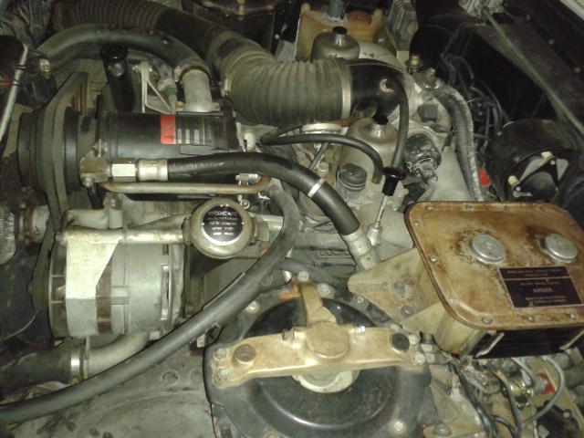 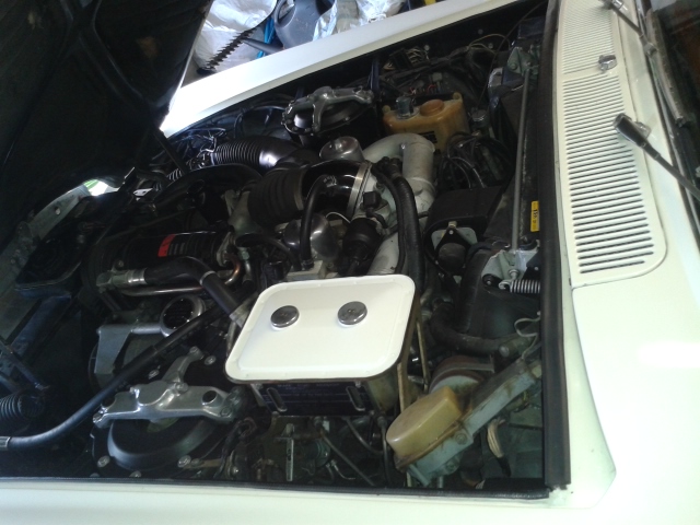 | ||
Geoff Wootton Grand Master Username: dounraey Post Number: 893 Registered: 5-2012 |
Shane Congratulations on making a superb job of cleaning (and polishing) the engine bay. I bought my car in Nevada, so the engine had a layer of desert dust over it. It looked awful, but drove great. On wiping off all the dust I found a previous owner had sprayed the entire engine with black engine enamel. My procedure was to spend time removing the paint with stripper and clean and, in some cases, polish the parts, as and when I had removed them for maintenance purposes. This of course tripled the time it took to carry out any work, but now, three years on I am pleased I took the time out to clean up the bay. Some people prefer the "patinated" look of an uncleaned engine. I remember Mike Brewer in Wheeler Dealers saying just that on inspecting the engine bay of a car he was checking out. I don't subscribe to it myself. In my opinion, a gleaming engine bay adds to the wow factor when raising the hood. Geoff | ||
Brian Vogel Grand Master Username: guyslp Post Number: 1582 Registered: 6-2009 |
Shane, I can't remember if you've ever posted your chassis number, but I'm now curious as to what it is. I haven't seen many examples of early cars with front height control fitted (even when it's been disabled, as most have) and your car definitely has the equipment. Brian | ||
shane alward Experienced User Username: the_gambler Post Number: 23 Registered: 5-2015 |
 | ||
Robert Noel Reddington Grand Master Username: bob_uk Post Number: 374 Registered: 5-2015 |
I noticed that the choke housing is black and the dash pots are unpainted. My car has a black painted inlet manifold. Silver horns. Unpainted stat elbow, dash pots, and choke housing. I have painted one dash pot in gloss black. I was going to do the other but felt a bit ill. So the second dash pot will have to wait until another day. I am undecided about the rest. The steel road wheels cleaned up with a power wash and scrub. I haven't painted them yet because they were still damp from the power wash. Old steel wheels need to be examined for rust. I only have a bit of surface rust. I have seen actual rust holes in steel wheels. | ||
Robert Noel Reddington Grand Master Username: bob_uk Post Number: 378 Registered: 5-2015 |
Both dash pots painted gloss black. There is a small vacuum maniflod on B carb just behind the dash pot. This has a allen screw which meters the vacuum. I painted it black. The breather elbow atop the choke housing black. The curved cover over the heater flap adjusters. Refinish black. The right hand side of the heater above the blower motor refinish in black. The scoop for the exhasut to air filter on wing nuts refinish in black. The originally black bits had no primer so I have followed suit. My inner wings are excellent original paint finish is cleaning up nice with WD40. All stickers intact. Last job was to take out each stat elbow bolts one at time and apply anti seize lotion in case access is need years later. Next detail under bonnet is header tank radiotor top tank and fan. The header tank will have to be removed the rad can stay put and be masked up. The fan will have to come out. I fancy red for the fan. One could say I am going to paint the fan red. Town. My car has lpg which looks a bit untidy where the feed pipes lay across the engine. So I shall see what I can do. I am thinking of removing the flexible pipes and replacing with copper pipe with just one piece of flexible pipe for engine movement. The water pipes for the vaporiser could also be more copper the rubber pipe. The heater box is held to the bulk head with nuts on studs. Fashion two brackets from 3mm thick steel and use these to support the copper pipes just in front of the bonnet catches. The steel road wheels have been wire brushed etc ready for lashings of black enamel. I am quite pleased with myself because the detail work on the engine bay has been done quite quickly and bit by bit the engine bay is starting to look very nice. I shall somehow post a photo. Tescos said I can use their Wi Fi so this may be a way around the problem. Resize on the lap top and send via the lap top. Bob, this should work for you. Have a go and post some test images in a new thread in the Idler Chatter section and I will delete them afterwards. David | ||
Robert Noel Reddington Grand Master Username: bob_uk Post Number: 384 Registered: 5-2015 |
Onwards with the detailing. The road wheels are thickly brush painted in a pile in the corner. 3 days to dry should do it. Heater box refinished in gloss black. I have soft masked it so the edge on the new paint merges into the old paint which is behind the engine. The air con compressor had a scabby bit on top so cleaned with purple 3M scotch brite WD40 and emery cloth for the worst bit. Then mask up label and surrounding area and a flick over with satin black. Because the air con is still just about working and therefore half charged (lasted 25 years) I didn't remove the compressor. Alternator the paint on the alternator is blue grey which is flaking off. I removed the alternator. Cleaned with emery cloth the paint fell off quick. Repainted in household enamel. Mix black white and a hint of dark blue amd brush it on. 1 day to dry. The lpg system that I designed and fitted was a mechanics intuition design that I cobbled together 10 years ago. I was right and the system works fine. But the aesthetics of the installation could be much better. The problem is that I used stainless braided super duper lpg hose and fine stuff it is except the outside dia is over an inch. It's so bulky. So I have taken the the carb assembly off the engine and replaced the bulk of the pipe work with slender copper pipes. I still have to have a flexible bit for engine movement. The bore of the hose is 16mm and the bore of the copper is 15mm. The outside dia is 16.5mm. This means I can tuck the pipe close to the choke housing thus giving a tidier look. The copper will be painted silver Hycoat caliper paint which I have laying around doing nothing. Also the carb inlet horns are to be silver and the little black tea cozy over the choke solenoid needs black paint. All the detail paintwork is being down with aerosols apart from wheels and alernator. The vapouriser coolant system. I offered up more copper pipe and the twists and turns make copper pipe unsuitable. So I am looking for a better route for the rubber heater hose type pipes. Still have problem with screen wash bottle I can find a place to put it. I am quite enjoying myself. | ||
Robert Noel Reddington Grand Master Username: bob_uk Post Number: 388 Registered: 5-2015 |
The carb assembly with new design of lpg pipe work is finished but still on the bench. It looks very nice. The horns are repainted in silver as is the lpg pipe work. The lpg pipe work looks like its meant to be there rather than the previous design which stood out like a sore thumb. Next is to clean the top of the engine and highlight the Rolls-Royce words on the rocker covers. A bank is easy but B bank is a riot in a plumbers merchants. Slight cock up the paint on the alternator nice finish in the wrong colour its not blue enough and too light. So far over 30 hours. Garage rate 60 quid an hour. 1800 beer tokens plus vat. Its a labour of love. | ||
Robert Noel Reddington Grand Master Username: bob_uk Post Number: 394 Registered: 5-2015 |
Reassembled the carbs back on the engine. When I turned on the ignition. Both hydraulic pressure lights were out. So I pumped the pedal. No 2 came on with one pump and No 1 20 pumps. This engine was last started 6 days ago. The hydraulics have held pressure for 6 days. No 2 went first because of the ride height sucking the pressure over 6 days. The engine fired first time and ticks over a bit fast at 750 rpm. The by passes are 1 and a bit turn open. So a trim back here needed. No petrol. Started on LPG. The kidney shaped gasket between the carb and inlet manifold has the middle removed. This allows an internal leak between the two carbs which improves carb balance at idle. The gap is too narrow to make any difference at higher rpm. Many twin carb set ups have a small bore balance pipe between the two carbs. While the carby toots were off I serviced the single point dizzy. The cap and rotor are 41 years old and in good order. The points are 25 years old. A quick stroke with a points file and run engine with dwell meter. Bang on the money. The spark plugs are 3000 miles old so I have left them alone. The oil and filter Mobil 1 is 2500 miles old and dark amber in colour. So still good to go. Next is the header tank and radiator top tank and redo the alternator, wrong colour. The new design of LPG delivery pipes looks much better and works fine. However I have an even better design in mind. The lpg goes down a pipe to a tee piece. The tee piece is in the middle. So that the pipes from the tee piece to the carbs are equal length. BUT thinking about it the pipes don't need to be equal length. This would allow me to locate the tee piece in more advantageous place. I am pleased with the work. The engine starts first time and idles smoothly and reliably. Fluid wise the car needs transmission oil and final drive and RR363 and antifreeze. Todays work took 5 hours. | ||
Robert Noel Reddington Grand Master Username: bob_uk Post Number: 400 Registered: 5-2015 |
The big black hose to the choke housing has just split half way down where the resonator is. These hoses are fecking expensive. I suppose get the black gaffer tape out. The pipe is quite large considering the resonator narrows down to half. But I suppose Crewe did it for a reason. I could design better. Also my carbs are serial numbered in sequence. Nice to see that. The prefixes and different but the numbers are 1 number apart. | ||
Brian Vogel Grand Master Username: guyslp Post Number: 1597 Registered: 6-2009 |
Bob, Replacement trunk hosing has been discussed on these forums in the past. Download the RR & Bentley Parts, Repair, Restoration & Other Resources Compilation and search for "Substitute Air Intake Hose." I give a link to one option on Amazon. Brian | ||
Robert Noel Reddington Grand Master Username: bob_uk Post Number: 401 Registered: 5-2015 |
I have fixed it with gaffer tape and covered the gaff with insulting tape. Flying bricks do a metre for 65 quid inc vat. No hurry I shall ask my pipe man. I have replaced the terminals on the coolant probe in the header tank with male 6 mm spades. And remove the terminals on the wires to female spade using brass spades and moulded plastic covers. It looks ok. The rubber boot over the terminals has split. Started to rub down rad top tank and header tank. But got bored so I watched a film instead. Hitchcock's The Rope. Todays work took 4 hours. | ||
Geoff Wootton Grand Master Username: dounraey Post Number: 903 Registered: 5-2012 |
Hi Bob You should check out Brian's resource file. The substitute air intake hose he refers to is only $26.53, that's a quarter of the FS price. It is also superior as it has the end finishers that fit perfectly. It beats gaffer tape - looks so much tidier. I've had one on my car for 2 years now - looks great. http://www.amazon.com/s/ref=nb_sb_noss_1?url=search-alias%3Daps&field-keywords=spectre+9751 Geoff | ||
Robert Noel Reddington Grand Master Username: bob_uk Post Number: 404 Registered: 5-2015 |
Geoff I saw the hose I shall show it to my pipe man. I need a new one because the underbonnet heat will shrink the tape and it will look a mess. I am sure my pipe guy will be able to get one at the same price or less. The genuine RR one with the protective thick sleeves and resonator is very very expensive. As I said no hurry because the original is ok for testing ect ect. Also cash is tight due to a delayed cheque in the banking system. Once the cheque clears I shall buy a hose, 5 litres of GL4 gear oil, 5lts of ATF, 5lts of Dot 4 brake fluid, 1/2 litre of castor oil and a gearbox filter and gasket and a sherbet dab. Me being short of funds has made me use up stuff on the shelf which was going to waste. Normally I just buy new stuff. So far I have spent only �2.50 for polish and �1.10 for peanut butter to polish the coolant hoses. On the credit side I ate the rest of the butter on toast. So 3 quid spent on the car. What a tight wad. Incidently Castor oil EP the EP means either extra pure or proxlated. The proxlated means its stable. What extra pure means I don't know. Maybe someone could explain. | ||
David Gore Moderator Username: david_gore Post Number: 1722 Registered: 4-2003 |
Bob, I always thought EP meant "Extreme Pressure" indicating the oil was intended for arduous high-load applications. | ||
Brian Vogel Grand Master Username: guyslp Post Number: 1598 Registered: 6-2009 |
I've never seen EP used in the context of lubricants for motor vehicles where it didn't mean "extreme pressure". I've never seen any castor oil marked "EP." Brian | ||
Robert Noel Reddington Grand Master Username: bob_uk Post Number: 407 Registered: 5-2015 |
Now 3 versions. Extra pure Extreme pressure E something proxlated which is the one for yak363. My local chemist has none but I shall ask him to spill the castor beans and explain and where to get the stuff. Again no hurry plenty to do before I change brake fluid. Got nuts to polish first. I got bored with TV so I finished the rad top tank and the header tank in household gloss black enamel. I brushed it. I have a theory that the mechanical action of the brush makes the paint bond better to the surface. Probably wrong. It looks nice. The steam valve label I careful painted around. Also whilst looking for my 6 BA spanner I found 2 grommets to fit the bonnet taper pins. Else the bonnet eobbles in the hole and chips the paint like the boot lid is prone 2 when the corner extra rubbers fall off. The genuine grommets are �10 each.Thats the antifreeze paid for. My way is when I see something that needs fettling I stop and do it. I contain the work to one section of the car at a time. At the moment engine compartment. It takes time but the end result will be good. In any case this is part of me getting better healthwise. | ||
Robert Noel Reddington Grand Master Username: bob_uk Post Number: 408 Registered: 5-2015 |
The engine compartment is finished. It looks clean tidy and shinny. Rear brakes suspension and final drive etc. First stage is inspection. Left hand drive shaft boot is split. The oil has leaked out. The whole lot needs cleaning before any work is done. I use a wire brush and a workshop vacuum cleaner. | ||
Robert Noel Reddington Grand Master Username: bob_uk Post Number: 414 Registered: 5-2015 |
The rear calipers and hand brake calipers are sticky. I done the left side service brake. 1 hour a short day. | ||
Robert Noel Reddington Grand Master Username: bob_uk Post Number: 421 Registered: 5-2015 |
Both rear calipers and hand brake arms are free and serviced. I painted the top half of the calipers blue and the bottom green. This IDs the circuits. Blue is no1 brake and green is master. Next the drive shafts. The left hand drive shaft boot is split. So pop both drive shaft out replace boot and swap over. Paint black. The rear brakes took 4 hours. Because I am a slow methodical worker who polishes brake pad pins etc. And then starts painting things. It's a hobby so why rush. In the fullness of time etc etc. I give the time taken so that others know how much time is needed for various jobs that have to been done from time to time. | ||
Robert Noel Reddington Grand Master Username: bob_uk Post Number: 431 Registered: 5-2015 |
Todays episode. The last exhaust box is rusty grotty. So I cut it in half to see what type it is. The last box and tail pipe is a Cherry bomb type resonator. Perforated tube wrapped in rock wool. I have made a new resonator. The perforated tube 60mm dia is made from stainless steel mesh. This is inside another tube 150mm dia the gap is packed with rock wool. Then caps welded on the end with a bit off mesh sticking out. Over the bits sticking out is welded 60mm x 3mm thick stainless pipe. The other end has 60mm pipe which connects to the rest of the system. All I need to do is finish seam welding and make a bracket to attach to the hanger by the spare wheel cradle. The next job was to tune the LPG vapouriser. The vapouriser is an OMVL 90 E. This is a very common vapouriser. To tune. In the feed pipe to the carbs is a restrictor. This is opened up to full. The vapouriser has two brass screws the 8mm one is idle bleed and the 10mm one is the relationship ship between the diaphragm and the gas valve. Start engine warm up. The idle bleed allows gas to flow independent of the diaphragm. Screw valve in and the gas is shut off screw out until engine idles smooth. Mine is 1.5 turns out. The 10mm valve and restrictor in the feed. Run engine at 2000rpm screw restrictor in until engine falters then screw out until max revs without moving the throttle. Then plus one turn. The 10mm valve. On the same setting 2000 rpm screw valve to get max revs again without moving the throttle. The next bit requires a road test. But I have a base line to work to. The idle bleed should not need further adjustment. Time on exhaust 5 hours and 10mins for the tuning. | ||
Robert Noel Reddington Grand Master Username: bob_uk Post Number: 436 Registered: 5-2015 |
Finished welding the rear exhaust assembly. I wanted to make the rear exhaust in 304 stainless but when I costed it. The price of the stainless is �300 inc welding wire. I managed to get 6 " of 60mm X 3mm wall 304 for the tail pipe and mesh for the cherry bomb resonator for nothing. The rest is 16swg mild steel. The 3mm wall tubing would be great for exhaust piping but its even more expensive than normal stuff and differcult to bend. The one I made has cost �5- �10. In my experience my home made systems last approx 10 years. Which is fair enough. The exhaust sounds fine. Not to loud Time 2 hours. Then put all the tools away and vacuum the workshop. 1 hour. Making exhaust mufflers is not differcult. Well within diy scope. The under side of my boot floor is like new. Next is the front brakes and hub brgs. | ||
Robert Noel Reddington Grand Master Username: bob_uk Post Number: 439 Registered: 5-2015 |
The front brakes were filthy with snot and brake dust. So a good scrub with a stiff brush and soapy water and blow dry. Followed by a blue rinse and high lights. I slipped the pads out and un mounted the calipers and took the hubs and disks off. I am out of Castrol LM Grease. So. My car came with a push button Motorola radio. Fitted between the front seats. I sold the Radio. The CD Radio is a Din unit so does not fit. I made a plinth. Unfortunately its not as good a the RR one. So I cut the RR one to fit. Masking tap the front. Carefull draw the cut lines. Drill 3mm hole each corner. Using a craft knife cut deep so that veneer below is cut. Then cut along the line with a fret saw. Nice and gentle no rush. Because the finished plinth is now slender I brushed a coat of lacquer on it. The end result looks nice. This piece of trim was of no value because it didn't fit so the decision to cut was easy to make. The original plinth has two metal insets in the holes so that the nuts holding the radio in can be firmly tightened with crushing the veneer. A RR refinement. 5 hours | ||
Robert Noel Reddington Grand Master Username: bob_uk Post Number: 463 Registered: 5-2015 |
I brought some grease which I lost and found 2 days later in the larder with the baked beans. So the hubs are greased and the calipers remounted. While the police were investigating the missing grease. I have made an extension to the centre consul so that it reaches the rear seat. Used black leather and sponge glued to a wooden frame. I only have 2 rear seat belts which means 2 passengers only in the rear. The hub bearing nut split pin is bent so it doesn't foul the earth contact in the grease or hub cap. I have managed to lose a grease nipple from a ball joint. Are they 1/8 BSP thread. They cost 20 pence each. But 3 quid postage so I will pop into the brg shop. 3 hours. If I was employing me as a mechanic I would sack me for being so slow. I am a bit like James May I continually put tools back where they go in my tool box. Next jobbet is wire brush the suspension. The top and bottom ball joints or swivels are sealed with no nipples so I have lowered the left hand top swivel boot. It is shinny and the zinc plate is as new and it has grease. A bit more won't do any harm and satisfies my mechanical bent. A danger is though that a boot is damaged which is a new regulation that is applied retrospectively by the MOT. Why RR fitted flat greasers to the front and ball nipples to the prop and drive shafts is another RR mystery. Both types are good and do the same job. | ||
Robert Noel Reddington Grand Master Username: bob_uk Post Number: 493 Registered: 5-2015 |
The suspension is finally clean it has taken hours. The rear tail box exhaust mounting has fallen apart. I have removed the whole assembly. 3 1/4 UNF bolts. Earth bonding strap is also broken. The 2 spring cups either side of the bracket have rotted away. So I shall make new cups from mild steel with a small bolt in the middle to hold it altogether. The design is pure RR it could have been done far cheaper and not necessarily inferior. But it's part of the car and will be repaired and put back. When I took the whole exhaust mounting off the steel of the chassis rail surprised me because there's no paint yet the steel is not rusty and the bolts just came undone without much effort. The steering damper. My car is right hand drive. The filler level plug is on the front of the damper and can be seen from the side if the left hand front wheel is removed. It appears to be 13/16 af spanner size. 13/16 seems to be a favourite RR size. Next job is check the damper oil level. | ||
Randy Roberson Grand Master Username: wascator Post Number: 513 Registered: 5-2009 |
The EP for RR363 is castor oil, "ethoxylated, propoxylated". Chemical treatments which previous research revealed increases castor oil's miscibility and ability to absorb and retain moisture without it separating out. It has a CAS number and can be purchased in bulk. I learned that plain old castor oil has numerous uses in industry and in cosmetics and medicines. There is an entire castor oil industry of which most people are completely unaware. | ||
Robert Noel Reddington Grand Master Username: bob_uk Post Number: 498 Registered: 5-2015 |
The level/ filler plug on the steering damper is 15/16 AF or 24mm AF socket size. It has a aluminium sealing washer. The level was a bit low so I put about 100ml of Dexron and that brought the level up a dribbled in the bowl. The washer I reused. The oil isn't above the bottom of the plug and the oil doesn't splash around inside the damper. The rear tail pipe exhaust mounting spring cups. Made these from aluminium. I bolted them to the bracket back to back. It looks like Crewe made them. Perfect. I thought that the design is over the top. But how long do rubber ones last 10 years at best. The RR design has lasted 41 years and only broke because I manhandled it while fitting the tail pipe. Its cost nothing to repair. I bolted the mounting to the chassis with thick grease between bracket and chassis. Also made a new earth bonding strap. Earth bonding is necessary for bad radio reception areas. Modern FM uos much better so earth bonding in my case does nothing. But Crewe fitted one so it has to be repaired. Thick copper multi strand wire with a bolt eye at each end. Next job is the right front trailer caliper. I am not happy with the action its dragging. Strip and clean. A little trick. It the front wheel brg is adjusted with a SLIGHT amount of end float because they are taper roller brgs the brake rotor will rock SLIGHTLY this will knock the pads and pistons back a SMALL amount. But I will strip and clean. I am also chasing down dust boots without buying main seals. The guy I have been talking to is suggesting about a quid each. But he needs dimensions. So strip down will reveal the measurements. Castor oil is indeed a big business because it has so many uses. Boots chemist wont sell to pregnant women because some have tried to use castor oil to induce labour and its dangerous. Also used in food stuffs. | ||
Robert Noel Reddington Grand Master Username: bob_uk Post Number: 508 Registered: 5-2015 |
I have no rubber grease so I took the socket out of the boot. Its about an inch long oval sort of and fitted below the isolation battery switch. The socket disconnects when the battery switch is off. The power comes from the front of the car. The voltage drop is too much for the socket to be used for charging. The small hole is positive. I made wander leads with red and black plastic plugs. I can't really see a use for the socket. But its there and it might as well work. The carpet up the side is glued to thick cardboard. This was warped. To fix I sprayed the back with water and squashed it between the table top and a thick bit of ply weighed down with buckets of water. Nice and straight. The beauty rings. They are getting tatty. 2 of them are actually pin holed with rust. I filled them with bondo about 15 years ago. At the time I made 2 replacements with M4 studs brazed on the back. I hand planished them. I am going to use them. The two genuine ones I have drilled 1.5mm holes side ways through 2 of the studs so I can wire them after the clips are fitted as a safety feature. The rings will be gloss black I am thinking red coach line. What do you think what colour for coachlines on a black car. Suggestions welcome. The battery is doing weird things. At one stage it had 16.5v and when I loaded it the volts went to 10v. Then 2 hours later its appears to be fine. So battery is dying. 069 is correct battery in UK number system. Only �50. My jeep battery fits so it will do for testing purposes. | ||
Randy Roberson Grand Master Username: wascator Post Number: 515 Registered: 5-2009 |
Seems to me most often the coach lines coordinate with the interior. | ||
Robert Noel Reddington Grand Master Username: bob_uk Post Number: 509 Registered: 5-2015 |
My interior is grey leather so silver vould be the colour for coach lines. The body has no coach lines. The car is black. Easiest way is to have black coach lines  | ||
Robert Noel Reddington Grand Master Username: bob_uk Post Number: 513 Registered: 5-2015 |
The red rubber grease turned up today 500g �8.80 which is enough to do many many calipers. Take a dollop out with a clean finger and put it on a clean sheet of paper. This must not be returned to the can. One dollop per two callipers. I split the calliper. 5/8 AF bolts and 9/16 AF bolts and 3/4 AF caliper mounting bolts. Use breaker bar on bolts while still fitted to car 1/2 turn on each. The leading caliper has a bolt that is close to the track end and a socket wont go. These bolts are tight so use impact sockets on breaker bar. To remove the pistons I used a 3 jaw lathe chuck to grip the inside bore of the piston a turn and pull and the pistons came out. The lathe was not running and the spindle was locked. Other way is grease and grease gun or air. The air method is using stored energy and a danger of misted brake fluid and pistons flying around the workshop. So I avoid air. Originally I was only going to do one caliper but have decided to do all 6. The piston in a caliper is actually a rattling clearance fit in the caliper bore. The main seal does all the work. My pistons have light pitting which is above the seal when the piston is fully home. The caliper bores above the seal were dirty not quite rusty. I carefully scraped the dirt off with a craft knife blade and a bright light, must not hit the main seal. Then red grease piston and bore and main seal. Push piston in squarely it should glide in with finger pressure. Leave piston slightly out. Fill back if dust boot with red grease. Fit boot fit large wire clip. The gallery seals. These must stand slightly proud if not then flying spares do them for �6 each and theres 4 on solid disk cars and 8 on vented disk cars. These seals expand under pressure and seal them selves. But they must clamp by being proud. If they are not proud then the caliper can leak when not under pressure and not leak when under pressure. They don't fail catastrophically they just lesk slightly and make a mess. If the bolts that hold the caliper together are wet with fluid this could mean a weepy gallery seal. 2 of the 4 bolts are next to the gallery seal. Assembly the halves and nip the bolts up mount the caliper and fully tighten the bolts. Lean on the breaker bar and give a bounce to 'king tighten them. I use a smear of red grease on the threads. Flying Spares do a kit for 4 calupets for �40 odd. This is a competitive price. Normal cars only have 2 calipers and generally an axle kit for a caliper is around 20 quid. Das Boots. Or Dust boots. These are not available separately. If split then apart from trying to glue the split and failing dismally. Until it can be sorted out. Usually the split isn't found until one is doing the pads. Clean with brake cleaner. Then remove dust boot refill with red grease. Then order new boots. Some calipers don't have dust boots and the pistons must be cleaned before the pistons are retracted. Usually the manufacturers sell a special grease that is applied when the pads are changed. The grease is probably red rubber grease in tiny tubes. AP racing. So a split dust boot will be ok for say 200 miles while the new ones are in the post. The port threads are M10 fine. The pads front and back have worn down by about the same amount. Must mean that the brakes are all doing the same amount of work sort of. Even the master circuit. Thats an indication of how good the design is. For those who are new to brake calipers these calipers are the same as any car weather RR363 or LHM. They are very simple to overhaul and obvious. Tip. The seals are easy to fit with fingers only, small screwdrivers can slip and bugger a seal up especially when fitting the dust boot clip red grease helps greatly to make things just slide together. Also red grease is not unpleasant to touch. | ||
Robert Noel Reddington Grand Master Username: bob_uk Post Number: 515 Registered: 5-2015 |
While the front calipers were off. I took the right hub off to check the back of the disc where the rotor is joined. And repack the hub bearings Castrol LM grease. Behind the hub and rotor is the weather shield. The shield does two things it keeps some of the weather out and also shields the bottom ball joint from brake heat. The top ball joint is much further away so doesn't need heat protection. The heat shield is held on with 4 socket head bolts 4mm allen key fits. Behind the shield is the bottom ball joint. This has no grease nipple. So by carefully lifting the boot squirt engine oil in which will soften the old grease. Then squirt grease in using a plastic syringe. I used CV joint grease. My shields are rusty and falling apart. So I made new ones from 16swg aluminium. The main thing is that the bottom ball joint is shield from heat. So I for simplicity made the bottom half only. Unfortunately one of the fixing bolts sheared. Drilled and tapped a new thread. 3/16 UNF. Time taken 6 hours one side only. My mate reckons that steel would shield heat better than aluminium. I think the opposite. But we both agree that the difference is small so not worth worrying about. Weather shield. Strange term because weather doesn't mean bad weather. Does the weather shield protect against good weather as well. The beauty rings are now painted and looking good. They are now bubble wrapped on the shelf awaiting fixing to the wheel embellishers. I tried to pinstrip a spare using my lathe. It was awfully awful in its awfulness, so no pinstrips for now. In tee one a record deck was used and proper brushes. An option is to get a vinyl shop to print a circle pin strip and stick it on the beauty ring. I did a similar thing with a petrol tank for a custom bike. The print was of a celtic design. The tank was then heavily clear coated. It looked smashing. This is easy because petrol tanks are small. Different ball game on a big car though. | ||
David Gore Moderator Username: david_gore Post Number: 1739 Registered: 4-2003 |
Bob, I deleted your duplicate post and whilst doing so observed you have been granted the status of a forum "Grand Master" - please accept my congratulations for this well deserved recognition of your contributions to this and other forums over the years. Our own contact started around 2002 through the much-lamented Swammelstein Shadow Forum and later through this forum. Long may it continue....... I have been pondering your request for suggestions for a coach line colour and the best I can offer is for a rich red or gold coachline, most other colours I can think of do not complement the black body colour. I have agonised over suggesting metallic silver to match your upholstery but this would have to be in the form of a tape and not painted as original. | ||
Brian Vogel Grand Master Username: guyslp Post Number: 1674 Registered: 6-2009 |
David, why could metallic silver not be painted? There are several variants on metallic silvers in the original Shadow series colors or, heaven forbid, one could simply have one mixed up for coach line painting. Brian, who also doesn't find skillfully applied coach line tape an abomination, either | ||
Robert Noel Reddington Grand Master Username: bob_uk Post Number: 516 Registered: 5-2015 |
I have alteady decided to go for imperial red which is nearly maroon. The coach lines on the car will be done with special masking tape. My effort at doing a beauty ring badly is not wasted because I now know how differcult it is. I have seen a tool called a paint wheel. Its like a miniature line marking cart used to mark football fields. Humbrol do suitable enamel paint. But first the dirty mechanical stuff. Today nothing got done because didn't feel likr it and repaired my grandsons bike instead. | ||
David Gore Moderator Username: david_gore Post Number: 1741 Registered: 4-2003 |
Brian, I have found metallic/pearl paints applied with a brush are prone to colour variation due to the metallic/pearl additives following the brush direction instead of being randomly distributed as they are when sprayed. The tape alternatives do not stand close scrutiny as they stand proud of the body paint and can be seen for what they are rather than painted coach lines that blend with the body paint surface. I have not seen a commercial coach line spray mask that matches the R-R/B hand painted profile and I would not have the patience let alone expertise to try and mask the coach line freehand. Fortunately, there are still sign writers and vehicle painters trained years ago when coachlining was taught in trade courses who can still do high quality work. Also hand painted coachlines are usually solid paint and not metallics/pearl so colour variations are not usually a problem. | ||
Robert Noel Reddington Grand Master Username: bob_uk Post Number: 521 Registered: 5-2015 |
The special masking tape has come a long way Also coach line ready coloured tape is much much better than the old stuff. Metallics can't be brushed and due to the narrownest of the line pointless a solid colour is better. The paint needs to go on in one hit. Touching up mistakes is not possible. It will stick out like a sore thumb. All this is for later on. My aim is to be subtle hence imperial red. Imperial red and black is a classic combination for old cars. | ||
Robert Noel Reddington Grand Master Username: bob_uk Post Number: 526 Registered: 5-2015 |
All 4 front calipers are now serviced and fitted on the car. Strangely the left hand brake weather shield is in good nick. So I have refitted it. The next job is the rear calipers. Once the rear calipers are done I will dump the brake fluid and refill with DOT 4 brake fluid and bleed / flush. The front calipers were quite clean inside. No sludge. I have left this to last because the reservoir lid has been painted with Imron paint and I want to make sure that the paint is fully hard. Plus I have lost about 1.5 litres of fluid doing the front brakes so once rear are done there will be less fluid to dump. I have forgotten to breaker bar tighten the 3/4 AF caliper mounting bolts so that is priority tomorrow. This is how mistakes occur. | ||
Robert Noel Reddington Grand Master Username: bob_uk Post Number: 529 Registered: 5-2015 |
The mounting bolts for the left hand front calipers have been tortured for being disobedient by being slightly loose. The rear calipers have fought me all way from tube nuts seized on pipes to bolts that wouldn't come undone till I got thw big tools out. The left hand side is done the right hand side is on the bench with brake fluid soaking into the hand brake pivots. The bridge pipe. My car has been piped with the bridge pipe going to the higher port on the back of the caliper with the bleed nipple lower than the bridge pipe. Wrong the nipple should in upper port this is part of the master circuit. ( green ID colour lower smaller pistons.) The complete caliper is quite heavy so I support it with a bottle jack while starting the mounting bolts. 3/4 AF. The 4 bolts that hold the caliper halves together are 3/4 AF or 19mm AF. All the pipe tube fittings and bleeders are 3/8 UNF threads. The handbrake pads have Lucas 20 stamped in the back. I have broken the outer small spring that holds the outer hand brake in. So new spring is needed. Nothing special probably modify a tension spring to fit. Could be stronger spring as well like the inside ones. I will be glad to get the high bollocks finished because I hate touching brake fluid. The fluid coming out (3 years old) is clear amber good sign. Note the colour of the fluid is most definitely NOT an indication that the fluid is any good. Next job is clean the reservoir and fill with Dot 4 brake fluid which will suck up any damp old RR363 still in the system. The levels in both reservoirs is now very low. Ideal time to clean. I am not going to cover bleeding because this has been covered many times in detail unless something weird happens. These postings and many words give an indication to the less knowledgeable on Roycery how much work a Shadow requires. All of the work done so far is within the scope of car diyer with a reasonable tool kit. No special tools have been used. Also in the beginning I said manageable chunks. I take bits off overhaul and then refit. That way the car stays more or kess in one piece and bits don't get lost. Except for a grease nipple which I found after wasting 46 pence on a new one. Note to clean the reservoir I use a wet vacuum cleaner with a glass flagon in circuit. The vacuum cleaner is cooled by flow of air. This means that if the air is moving slowly due to small bore suction pipes ( screen wash tube) then the vacuum cleaner could burn out. So mine has a bypass which lowers the vacuum. The valve is a simple hole which I put my thumb over for max vacuum. I use the vacuum for about 2 mins at a time and then turn motor off. The reservoir isn't that big. | ||
Robert Noel Reddington Grand Master Username: bob_uk Post Number: 532 Registered: 5-2015 |
Rear caliper bridge pipes. These are very close to the wheel and can touch. So important to check. Also the pipe must be at least 5/16" away from the rotor. | ||
Robert Noel Reddington Grand Master Username: bob_uk Post Number: 533 Registered: 5-2015 |
Both rear calipers refitted. The hand brake levers are nice and free and move under their own weight. The reservoir had a bit of black scum not quite sludge in the bottom. The 3 filters are clean and not collapsed. So no problems in the reservoir. | ||
Robert Noel Reddington Grand Master Username: bob_uk Post Number: 535 Registered: 5-2015 |
The reservoir is now back together with no problems. I done a quick bleed. Which will do for now. I have run out of brake fluid. So grease the drive shaft UJs. Top up the final drive and the inboard drive shaft joints. These were all changed about 5000 miles ago. The left hand one was empty because I fitted a new boot last month. The oil is 75/90 GL4. The makers reckon its good for 50k miles and Ford say the life of the car. The final drive was up to level as was the right hand inner joint. I polished the final drive filler plug. So I took the petrol tank drain plug out and polished it as well. To finish off the brakes at the wheels brake job I have colour coded the pipes an calipers. Blue is no1 all wheel brakes. Front leading and rear upper calipers. Green is the master system. Lower rear calipers Mauve is no2 brakes front trailing calipers. | ||
Robert Noel Reddington Grand Master Username: bob_uk Post Number: 545 Registered: 5-2015 |
I stopped work because I had no brake fluid and the workshop needed cleaning. Today I looked at the ride hydraulic bits and bobs and got out the necessary tools to check the flow to the rams. Simple job connect bleed tube to bleed nipples. The pink circuit. The battery failed completely. So I called it a day and watched the TV. I knew that the battery was going to do this sooner or later. I reckon that the hoses are blocked. Then check the fast solenoid signal flow. If the fast solenoid is clicking but not signalling then the restrictor(s) are blocked. | ||
Robert Noel Reddington Grand Master Username: bob_uk Post Number: 553 Registered: 5-2015 |
The out put from the ram bleeds is a mere dribble. I connected a gauge in leiu of the bleed nipple and eventually the gauge went to a feeble 100 psi it was still going up. Lowering the link showed the pressure was slow to drop. The hoses need to be checked. The brown circuit from valves to rams. The unions are tight so applied a spot of brake fluid to the unions and bled the master circuit instead. The green circuit. Normally this car bleeds out quick but not this time. So fit thin pads to the caliper pump the pistons out. Open nipple push pistons back in. Loads of air. That sorted it. Nice high pedal. Be careful with this method because retracting pistons moves a lot of fluid. The rat trap will have to be exposed to check the clearance between the master cylinder lever prongs and the frame spacer it should be 0.800". I have a slug of steel that is 0.800 long. I turned it in my lathe years ago for this job. Also the master cylinder warning light isn't working. There's a switch which makes contact should the travel be excessive. It works with the test button. Plus spray linkages and pivots with motorbike spray grease. Clean out cover. New practice when changing pads on abs cars is to open the nipple so when the pistons are retracted the fluid doesn't go throu the abs system. Also advantage is the system gets a bit new fluid. I am now doing this to all cars abs or not. The Shadow has delicate expensive brake valves which don't like manky caliper fluid. Interesting feature in the reservoir. The feed for the master is higher than for the pumps. The filter sits on a tower this tower is a little reservoir for the master cylinder circuit. If the power side leaks out the master still has its own supply of fluid. If the master leaks out it can only lose half the fluid leaving a supply for the power side or pump. Simple but clever. The more I see the more confidence I get in the safety of this system. I connected a 3 watt bulb in series with the solenoid valve. This checks power to the coil and continuity of the coil. If it doesn't light then connect test lamp in parallel. Mine lit up so coil and power supply is probably ok. If the test lamp wires are long enough it can be placed in view of the drivers seat. Mine operates in park and neutral with ignition on. I forgot to try accessory position. The restrictors are simple things with buttons and a roller inside. The restrictors are fitted to the feed to the solenoid valve orange and solenoid return which is white. The orange or feed one has a blanking plug which us 3/8 UNF a nipple could be fitted for flushing. It would be of little valve for bleeding though. But it would allow flushing before the valves. The orange restrictor is fitted right hand side and the white restrictor is fitted left hand side. In particular if the left hand white return restrictor is blocked the solenoid can't dump pressure. This holds the ride valves fully open. The excess pressure caused when the car goes over a bump will then send a slug of high pressure fluid down the return line which is tee pieced to the return line from the upper brake valve. The slug then travels to the trailing front calipers and the brakes momentarily come one. This can damage the hydraulic system. Hydraulic hammer like water hammer. It can blow flexible hoses. So not to be ignored. 41 years is long enough to build up sludge. Only part needed is the metal sealing ring under the 3/4 AF adaptor which is the return from the solenoid on the ejite restrictor or the solenoid feed if its the orange restrictor. The sealing ring is probably copper and will respond to annealing and reuse. So no parts required. All nice and easy to understand but its going to be a right fiddle get the pipe unions squarely started and then there's bound to be a steel pipe thats no good. Is it OK to reuse pipe fittings the answer is yes providing they are not damaged or deformed. Especially male tube nuts. The sealing end can splay out causing differculty in starting the thread. Fortunately they are cheap 10p to 30p. I have a 3/8 UNF die and taps. Brass ones are available. Also these fittings are not hard to make on a lathe. To make tube nuts start with a 3/8 UNF bolt. Female I make from stock hexagon bar. Bulk head adaptors I use threaded rod. I buy normal steel ready made but make the brass ones. For tee pieces I cross drill an aluminium block. Stole that idea from Crewe. To do female fittings. Drill through with 1/8 drill. Then drill 3/8 UNFtapping size to the correct depth. The angle of the drill is the same as the sealing angle. Then tap with taper tap then plug tap. If the seat is a bit rough then wire wool and hammer with punch with angle. I use a Dormer HSS drill with honed cutting faces. Worth spending a few hours getting the drill perfect because once its correct the fittings become quick and simple to make. The drill is only about 4 quid. I use Trefolux cutting grease this means the drill will do a 1000 holes in brass before sharpening. Brake bleed nipples are simply to fiddly to make and very cheap. If you want to have go at making these fittings check out the specs for the angles because the mating angles are not the same. Female is shallower than male. The seal is made not over the whole angle seat bit. But at the bottom in a narrow band. Stianless steel is not suitable it galls and blunts tooling breaks taps and chips dies. Saw some coloured code nipple rubber covers very snazzy. 30p each. Also if you flair to bit of copper brake pipe screen washer tube fits tighter. I have tube nuts on short lengths of brake pipe. Some are flair with washer tube. I wash them out after use with water. Very very useful. The others are fittings with out a through hole-- blind. Still its an engrossing hobby. | ||
Randy Roberson Grand Master Username: wascator Post Number: 524 Registered: 5-2009 |
Reminds of two related issues I have encountered: after overhaul of my 1970 Shadow's height control valves: the left side will not react I.e level but the right side will. I removed the restrictor on the right and opened it up but not the left. Possibly I being an amateur boo-booed up the reassembly of the control valve, the restrictor is clogged, or I Have a pipe on wrong. Another project to go with the removal and leak repair of the air conditioning evaporator. I notice on the '77 WraithII that, if it sits for several days after shutdown, the rear brakes lock. After I start the engine and the system pressures up they unlock. ?? | ||
Robert Noel Reddington Grand Master Username: bob_uk Post Number: 555 Registered: 5-2015 |
Randy the 2 restrictors are not 2 because of 2 ride height valves. There are 2 restrictors because the right hand restrictor restricts the feed to the solenoid valve. And the left hand restrictor restricts the return from the solenoid value. What confuses at first is that the 3 ports at the bottom of the restrictors are joined together and not restricted only the top port is restricted. The bottom 3 ports are like a 3 way union or tee piece. This allows convenient places to feed and return the 2 ride valves and 1 solenoid valve. 1 feed for 2 ride valves and a restricted feed for the solenoid valve. 1 return pipe for 2 ride valves and 1 restricted return for the solenoid valve. The pipes to the right hand restrictor are orange. And the left hand restrictor are all white. The righthand restrictor has 3 pipes and a blanking plug. The blanking plug is because instead of running a feed pipe to right then back to the left for the left hand ride valve there is a tee piece on the left hand side this is orange. There is also another tee piece which is connected to the side port of the solenoid valve which is signal pressure the tee piece then connects to both ride valves to engage fast mode. If the blanking plug is replaced with a bleed nipple the system can be flushed before the valves. Also it checks the pressure feed hose between body and rear cross member. Signal pressure is yellow. The left hand restrictor has 4 pipes and no blanking plug. 2 returns from the ride valves. 1 restricted return from the solenoid valve. Last pipe goes to hose which connects to the body and returns fluid to the reservoir. The pressure hose is SS braided. The return hose is normal rubber. The outer pipe is pressure and orange the inner pipe is return and white. All the colour ID sleeves on my car have perished and gone a dirty colour. Enamel paint instead keep away from unions because when unscrewed the paint will go yucky and smear over the threads and ports. Fliud strips enamel paint. Or small coloured cable ties. Or heat shrink but a union has to be undone. Or don't bother. Today I took the hoses between the ride valves and rams brown ID colour and they are knackered. I can't blow through either way. I cut one open and there's flaps of canvas like stuff hanging off the inside wall. Now there's yer problem. The hoses are 10 quid each. Normal rubber. They look the same as the front caliper ones but shorter. The SS braided hose which is the feed orange. Is fine because the nipple in the blanking plug issues lots of fluid at accumulator pressure. The rubber return hose white will have to be checked by removal and blowing. Its looks like the hoses from ride valve to rams hoses and is probably the same part number. Rather than refitting a 40 year old hose I might as well fit new one. I screwed a union and bleed tube to the left ride valve in lieu of the hose brown ID. And fluid issued quite freely from the ride valve when I pushed up the link. Note when the link is pushed up resistance should be felt just as the valve opens although the arm moves a lot the action is in a much smaller angle the valve inside only needs to open a small amount for the rams to start jacking. The valve is held shut by spring pressure when system has no pressure. Once pressure is up the pressure also holds the valve shut. It is this pressure that can be felt. According to Bill Coburn "considerable" resistance. Modern rubber hoses are much better than the originals. If the originals lasted 40 years then I will be dead before they need replacing. So rubber it is. Incidently if the outside of the hose is treated to a smear and a buff with red rubber grease it gives further protection. Also tyre walls. 500 grams tin cost �8.80 September 2015. For the really keen coloured heat shrink and coloured coded nipple caps are available. It is possible to assemble the ride valve incorrectly. Inside the restrictor is a small roller. Its important that the roller is not lost. Because unrestricted pressure to the solenoid valve can break something. The restrictor must be removed and cleaned on the bench. Note that Dave Gore blew a valve in half because of a wrongly connected pipe. Looking at the valve from the rear. The top rear port is hose to rams and brown. The bottom rear port is pressure and feed orange. The front top port is signal and yellow. The front bottom port is return and white. I keep repeating the ID colours so the reader can refer to chapter G. Unfortunately the diagrams aren't very good and also include front ride height and master circuit. The front ride height version has an extra hose from rear cross member to body. This is for signal pressure from the solenoid to the front ride height valve and is yellow. The lower rear pistons on master cylinder cars are operated by the master green. On the SY2 The lower pistons are connected to the front trailing calipers no 2 hydraulic circuit. The colour is mauve. Be careful about how you check stuff on the rear cross member. Fluid at pressure etc etc. Bucket of soapy water and sponge on standby. | ||
Robert Noel Reddington Grand Master Username: bob_uk Post Number: 564 Registered: 5-2015 |
I have left the brakes so that the entrained air leeches out thats my excuse. The screen wash bottle. This was on the right hand side to the rear of the spring pot. Instead now there's a vapouriser for the LPG. Behind the left hand front wing behind the road wheel has room for a 2.5 litre plastic anti freeze can sans antifreeze of course. There is a drain pipe in the space which goes through the inner wing to connect to the heater pendulum chamber just under the left hand blower fan. The hole in the inner wing is big enough to get a filler pipe through and a screen wash pipe. Theres a handy brace and anti drum pad from inner to outer wing. The washer bottle rests on the brace. The screen wash motor is fitted to 16swg aluminium. Also the filler pipe is attached. The aluminium has flanges by bending which give extra strength. Other wise if left flat the vibration will crack the aluminium. The pump is mounted higher than the bottle. Because the seals in the pump will allow water in the motor after time. By mounting higher this can't happen. The drain pipe from the heater pendulum chamber is about 1" to short so extended it with a bit of copper pipe which pokes out 1/4" below the sill or rocker panel. The drain pipe is clear and in good condition. Before the inner mudguard is fitted I shall rust proof and modify the mudguard to accommodate the new arrangement of the drian pipe. The mounting of the bracket for the filler and motor is undecided but it must not obscure the view of the sight glasses for the brake fluid. I am thinking in front of the spring pot above the anti dieseling air intake filter. Also the filler cap. This has to look Rolls Royce. Brass is good. The screen wash tube inside the bottle has a lead weight at the end to keep the end of the tube at the bottom. I am not using non return valves so the small tube can be cleaned with air. The space behind the wing is immaculate and looks like new. | ||
Robert Noel Reddington Grand Master Username: bob_uk Post Number: 585 Registered: 5-2015 |
No non return valve was a bad idea because the wash is taking 2 mins to get up steam. So I fitted an in line one under the pump. Now 5 secs. Thats good enough for the mot. I rarely use screen wash on any car. If its that bad a bucket and sponge is better. Other wise the wipers get ripped up. I always have a sponge with shammy cover in the car. The inner plastic mudguard is refitted and sealed with builders silicone. �2 a big tube for a caulking gun. New screws. The screen jets were blocked. Remove the jets complete from the chrome knob on the scuttle grill. Unscrew the cap from the 2 jets. The body should have a clear 1/16 hole up the middle. Mine were both blocked with crud. The tiny cap has a Trico logo on it. Very very small logo. Amazing. Work washer to flush to the chrome knob then screw the jets back in and adjust aim. Use a spanner not pliers one is bound to slip and damage the chrome or the paint. Next back to the hydraulic ride height. I am not keen to lay under a car with fluid dripping on me but I have to get stuck in. Once I have started I will be OK. But there's a good film on the telly etc. I have 3 new hoses 10 quid each. No new half nuts or crinkle washers. I should think the old ones will do. They only hold the hoses on. Just a nip with a 6" long spanner is enough. 9/16 AF spanner size. The thread as ever is 3/8 UNF. Could always turn down full nuts in brass. | ||
Robert Noel Reddington Grand Master Username: bob_uk Post Number: 597 Registered: 5-2015 |
The 3 hoses are fitted. The return hose from rear cross member to body wasn't blocked. I removed the pressure side restrictor orange pipes. It was clean. There is an O ring inside which seals the adaptor at the top. About 12mm dia replaced. There is no washer under the adaptor. I have connected a wire to the fast solenoid. The live side is green with yellow tracer. The wire goes to an LED which lights when the fast bit is on. If power is applied to this wire the solenoid operates. Which I am not going to do because the exsisting switch works fine. All the steel pipes are dirty but not corroded. Next is the other restrictor. Return and white. This is awkward and fiddly to remove from the cross member. However if I disconnect the return then operate the solenoid valve briefly when the valve closes ( no electric Power) a slug of fluid should go down the return. Which is the signal pressure yellow dumping done the return. If it does this then the restrictor is clear and pointless removing it. The risk is that a union gets damaged then it gets even harder to repair. Don't fix what ain't broke. Beauty rings. Getting a vinyl printed pin strip won't work it will be so flimsy and sticky it will be tears before bedtime. But instead have the whole lot printed. Like a big washer 8 inches in diameter. Also if printing additions could be added. Such as instead of a pin strip a ring of roses could look good. Or a ring of thorns. I am going to put the walnut burr centre consul bit back. The slot for the radio and holes I will cover with an aluminium panel. In which the LPG control unit will be mounted. Plus the LED for fast solenoid. Plus Rear fog lamp switch and LED. Plus 2 LEDs for the SU fuel pump. How to calculate the resistor for LED. V1 minus V2 divided by the amps of the LED. V1 is supply volts V2 is MAX forward voltage of the LED. Eg 12 volts minus 3 volts equals 9 volts. Divide by 10 milliamps. 900 Ohms a 1000 ohm resistor ideal. The flat on the side of the LED denotes negative. The SU fuel pumps. When the points open there is a voltage across the points. The coil is about 4 ohms. If a 3v LED is connected across the points the LED will blow. So connect a 1k ohm resistor in series with the points and LED. The 4 ohms means that the resistance is actually 1004 ohms so no problem. A higher than calculated resistance protects the LED even better. If the LED is to bright then increase resistance. Green LEDs are a substitute for instrument lighting. Also multi coloured LEDs available but needs more wiring and a switch. Maplins do mixed colour bags of 80 leds for 8 quid. I get mine from scrap electronics. The panel is to small to trim plus 5mm holes for LEDs. So maybe crackle black will look nice. Or veneer. Or vinyl printed walnut burr. The 2 gauges which are fitted to the existing panel which is black leather covered and I only liked it for 2 seconds after I fitted it. 2 hours to make and 2 seconds to not like it. These 2 gauges are going to replace the amp and fuel gauges which are going to move to the radio balance hole antenna switch hole. The antenna switch could go to the new panel or remove system entirely and use hidden antenna. Lettra set available from art shop for denoting switches etc. | ||
Robert Noel Reddington Grand Master Username: bob_uk Post Number: 602 Registered: 5-2015 |
I have made the panel. It doesn't fit over the walnut but behind it like the AC and heating switch panel below. It is back lit in green. The panel has the lpg control and an amplifier for mp3 player etc. The holes for the amp 3 knobs are where the green back lite shows. Also rear fog red 5mm led warning lamp. Amber led for fast solenoid warning lamp. 2 green leds which flash in time with the petrol pumps. The panel is made from copper water pipe split and flattened out. Copper because I can then solder brackets on to screw the amp and lpg control. The panel is held to the back of the walnut with small very short screws. This way no damage is done to the front. The panel goes full width and also covers the the radio spindle holes. I not sure about what to use them for. The amplifier was for a pc. 5 watts rms. It came with 2 speakers. I gutted them and simply soldered an old 3.5mm ear phones lead to the pcb board. The speakers are mounted just under the dash pointing downwards. I didn't want the complication of using the 4 door speakers which are used by the radio cd player. If the phone is plugged in then the phone works the same time as the radio cd. This lot has taken 10 hrs to make. More fun than laying under the car with dirt and brake fluid dropping on me. | ||
Robert Noel Reddington Grand Master Username: bob_uk Post Number: 604 Registered: 5-2015 |
Today I removed the SU pump for overhaul and modification. The modification is to connect a wire to the side of the points which goes dead when the points open. This wire goes to the cathode (negative) of a led. The other side of led goes to live. When the points close, both sides of the led are live. When the points open because the other end of the coil is earthed the led gets earthed and lights. The coil is about 4 ohms. The resistor for the led is 1000 ohms. So the led sees the coil as an earth. There are 2 leds 1 for each SU pump coil and points. The guards for the pumps were difficult to get off. The pumps came off easy. I got the leds from Xmas tree lights and the resistors and thin wire from an old amplifier PCB. So far this modification has cost zero money. 16 hours so far. Still whats the point of rushing a hobby. Its quite nice sitting at my bench listening to Radio 2 soldering stuff together and testing it. The 1k resistors mean the circuits work between 10v and 16v. I tested 1 led and 1k resistor to 44v and it survived and didn't get really bright. Also if polarity is reversed the leds don't blow. Total amps is 800 ma and is protected with a 2amp fuse. I don't fully understand how the resistor limits current and voltage. But it works exactly as it says in my book of circuits for children. I have a variable DC power supply which had built in volts and ammeter. And a mains operated digital multimeter. I am looking for a second hand oscilloscope but they are expensive. Interesting. If green and blue LEDS are placed next to each other the effect is more white than greeny blue. | ||
Bob Reynolds Grand Master Username: bobreynolds Post Number: 339 Registered: 8-2012 |
"I don't fully understand how the resistor limits current and voltage. But it works exactly as it says in my book of circuits for children. " A resistor only limits the current. But because there is less current flowing in the circuit, there will be less voltage drop across it (V=IR Ohms law). So reducing the current reduces the voltage, and vice versa. | ||
Robert Noel Reddington Grand Master Username: bob_uk Post Number: 613 Registered: 5-2015 |
Bob Reynolds, Thank for the comment I thought about the formula V = IR. R = V/I and I =V/R. The LEDs are max 3v. The amps are 20ma. The circuit voltage is 14v (nominal 12v). So 14-3v = 11v. The volts and amps are fixed and known. So R = 11/0.02 = 550 ohms. So 1000 for safety. But in the case of the pumps there is a 400v capacitor to consider. 397/0.02= about 20,000 ohms. I didn't have any 20k resistors so I used 100k and it works fine. The pumps are in good order and now pump fine. All that was wrong was dirty points. The filter was clean so a quick clean up and nail them back on the car using grease on all fixings. The panel is now bolted to the steel frame behind the walnut centre consul bit. Screwing to the back of the walnut made assembly difficult. I should have done that in the first place. The switch for the rear fog lamp is now fitted to this panel. Because of the low amps of Led fog lamps the switch is a mini toggle switch 1/4 inch spindle hole with chrome nut. The low amps of leds makes wiring easier due to thin wire gauges I can use. As a test I replaced the righthand reverse bulb with a single red led as a dim rear fog lamp till I get a proper led red bulb 382 is UK number. These bulb are actually not for road use but my car is not required by law to have a rear fog lamp so I shall ignore the law. In any case the cops aren't that petty and at worst will tell me to fix it. Leds follow the series rule. 5 3v leds in series equal 15v thus resistors are not required. If 2 lots of 5 are then parallel connected 10 leds. Which is how proper led bright bulbs are made. However a 100 ohm resistor should be used for safety. So the proper led bulbs have a resistor inside. I had a go at making a proper led bulb using a normal bulb bayonet cap. It went wrong. So I shall have another go. The rear lights and stop lamps have a relay on the stop lamps to warn of bulb failure. If the amps are reduced the relays wont sense properly and the warning light will come on because it thinks the bulbs are blown. So a load resistor is need. Which is the same resistance of the bulb 8 ohms. So not worth changing to LED. The dash lighting is worth doing as bulbs blow using green leds or any colour you like. And also the interior lighting. There are warm white leds now available. I have found a use for blown bulbs!!. Hit glass with hammer insert leds into the caps. While the drivers side lower vinyl cover where the bonnet release lever is. Is removed for wiring access. A common breakage is the flap of aluminium next to the bonnet has snapped due to it being pulled instead of the bonnet release. So using spring clamps and a bit of wood to hold it all in line. I made a small patch of aluminium, drilled some small holes in it. Then scatched up the aluminium of cover on the inside. Using bondo I glued the patch in place using a very thick layer of bondo. Which squeezes out of the holes and sides of the patch. Then just as the bondo starts to go hard scrap the excess of with small screwdriver. The idea is that the thickness of the repair is now 1/2 inch thick. 30 mins to set and the cover is solid with no flap hanging down. I should do this for living but what customer is going to pay �50 an hour for me to spend 20 hours just to fit an amplifier and a lpg control unit. When I did do this for a living I never had the luxury of being able to do stuff like this. Its so interesting and the hours fly by. | ||
Robert Noel Reddington Grand Master Username: bob_uk Post Number: 622 Registered: 5-2015 |
My pump warning lights. One side of my SU pump has stopped working. At first I thought my wiring was up the spout. But its the pump itself. So my system does work. So its pump back off and redo. What a cock up. Still if it was easy then everybody would be doing it. Probably points. My alternator runs at 14.2 to 14.4v max. At idle it drops off to 13.5 to 13.7 depending on how warm the resistors in the regulator are. As the resistors warm up the resistance increases and the regulator thinks the reference voltage from the ammmeter shunt is lower and ups the voltage. I can't do any thing about idle voltage because the alternator is not running fast enough thus the regulator and alternator rotor field go to max. As the revs rise the volts increase and the regulator backs off. If it didn't the volts would go very high maybe 60v which would cook the electrics and battery. But I can increase the volts at speed by connecting in series a diode in the reference voltage from the shunt. The forward voltage drop of the diode is 0.6v. This fools the regulator into thinking the volts is less than it is. But if the extra volts is continual the battery will be overcharged. So a switch shorts out the diode and the volts drop from 15v to 14.4. The oil and temp gauge. I am making a 2 gauge pod that fits just below the dash next to the centre consul. In the corner Righthand drive to the left of the steering wheel. Again I have chosen copper because its easy to solder together. To mount it I am going to solder strips of copper which will slip between the black trim and be screwed behind trim. Cover with thin foam and stretch black leather over it. The foam gives a soft feel and makes the copper sheet appear thicker than it is. I have decided not to interfere with the dash board. The risk is to great. Copper smithing is an old trade which I learnt about as an apprentice. Also I made my Dad a copper ashtray when I was 13 at school metal work. Copper work like ashtrays is Arts Crafts which preceded Art Deco and Art Nouveau. | ||
David Gore Moderator Username: david_gore Post Number: 1762 Registered: 4-2003 |
Bob, Your comment about your alternator running slowly has triggered a few dormant brain cells back into life with a recollection that two alternator pulleys were available for installation on the Shadows during assembly depending on the delivery destination of the vehicle. If my memory is still reliable, the "colonial" specification models exported to Australia were fitted with a larger diameter pulley to slow the alternator down as our cars spent more time traveling at speed than in stop/start city traffic and the standard UK pulley meant the alternator incurred more wear as a consequence in our part of the world. It is possible your car may have acquired one of these pulleys during its past life - if you are not having full charging problems due to the distances and speeds you travel in your car, I would leave well alone and consider using a float charger when you are not using your car frequently enough to keep the battery fully charged. | ||
Carl Heydon Frequent User Username: car Post Number: 72 Registered: 2-2004 |
In my experience, very few owners know that the CAV regulator has output pins for low, medium and high charge rates. | ||
Robert Noel Reddington Grand Master Username: bob_uk Post Number: 623 Registered: 5-2015 |
Dave nice to see you back. The reason for the switch is to return to lower volts when not required. On short runs at night a 0.6 extra volt will be handy to replace the juice quickly. I have never had charging problems or flat batteries when the car is in use. But have had a few close calls. The starter grunts and just catches it. In Dorset in the villages I park with parking lights on and the extra 0.6v will keep those headlamps nice and bright in the lanes. My wife is a star gazer and likes to go in to the sticks and star gaze. On longer runs the engine flies over and fires straight away. When the car is not in use then my boost switch does bugger all. So I will still be charging via my mains charging bench. I like charging batteries and noting the readings. The clock. I think the clock may run on 9v if it will I shall install a PP9 dry cell battery to run the clock. The light inside will still be running off the car. The idea being is that the clock will keep going while the battery is disconnected. I hate having to reset every time the battery is turned off. The battery will fit over the top of the fuse box for easy changing. I am very pleased with my copper instrument pod. Its going to held on by the cruise control bits. So no holes drilled in expensive trim. The pod is over size so I can trim for a dead fit. The lights for these instruments are green LEDs. A LED is 15p and a resistor is 3p. That's much cheaper than a normal bulb at 50p. Colonial alternator pulleys. How quaint and to some racist. ( The people that search high and low for offensive comments they work at the BBC) Assuming that my drive belt is correct then I can assume I have the right pulley. But these engines are known for drive belts being suppied that don't fit. At the moment I won't have a battery problem because I borrowed at battery from my ex-boss. Its a monster for a truck. Its 4 times the size of the 069 battery. All my battery problems are caused by me using to much power when parked. Photos. Unfortunately my son who does the inspector gadget bit on computers has broken his leg. He fell over, rotten bad luck. But while he is recuperating he will have lots of time. | ||
Robert Noel Reddington Grand Master Username: bob_uk Post Number: 624 Registered: 5-2015 |
Carl Heydon. The low medium and high are a series of resistors. The resistors are fitted in series with the reference voltage terminals(high med and low). The higher the resistance the less reference voltage that the rest of the regulator sees so the alternator increases volts. And vica versa Mine is on high this is standard on UK spec cars. Also calcium lead batteries like a slightly higher voltage. The circuit consists of a switch with a diode across the terminals and two wires. If it doesn't work I will just recycle it in to something esle. I enjoy mucking around like this. | ||
Bob Reynolds Grand Master Username: bobreynolds Post Number: 341 Registered: 8-2012 |
"My pump warning lights. One side of my SU pump has stopped working. At first I thought my wiring was up the spout. But its the pump itself. So my system does work. So its pump back off and redo. What a cock up. Still if it was easy then everybody would be doing it. Probably points. " Could this possibly be normal? To test your system, disconnect the working pump and you will probably find that the non-working pump starts working properly. As we know, the 2 pumps are not entirely independent. They both share the same pump chamber. As the pressure in the pump chamber decreases it could be that the same pump always triggers first, because of the difference in spring pressures, clearances, and other variables. So one of the pumps will be doing almost all of the work, leaving the other one doing virtually nothing unless the first pump can't handle the flow on its own. I don't know whether this is the case or not, but I would expect one pump to be dominant over the other one. They don't take it in turns! If this is the case, you don't need two warning lights, as one will be on all the time and the other one hardly at all. You just need a single light to tell you that the pump is working. So you can connect your 2 pump wires together via 2 diodes and just take a single wire to the LED in the car. This will tell you when either of the pumps is working. | ||
Patrick Lockyer. Grand Master Username: pat_lockyer Post Number: 958 Registered: 9-2004 |
Goodness me, what in the heck is going on, just pick a steep hill with four passengers and power the motor up the hill, you will soon know if just one punp is working or not,you will no doupt find other faults that will light up the leds like a Chrismas tree if you have them fitted. | ||
Robert Noel Reddington Grand Master Username: bob_uk Post Number: 629 Registered: 5-2015 |
There is no petrol in the car at the moment. So both pumps should be machine gunning. I haven't checked any further. The wiring to the pumps are covered by sealed rubber boots. So can't easily disconnect one pump on its own. Its a very minor problem that costs nothing to fix. I am still mucking about with my instrument pod. It has taken hours to trim it and fit it with out drilling holes in trim. All of the electrical stuff I have added is easy to remove and reuse on some other idea. Plus on the way stuff gets fixed like that bit of trim by the bonnet release. I have lots of time plus it's good for my mental and physical health. | ||
David Gore Moderator Username: david_gore Post Number: 1763 Registered: 4-2003 |
Bob has sent me some test images of his auxiliary instrument panel under construction and I am pleased to be able to have been able edit them and put them on the Forum: Front view; 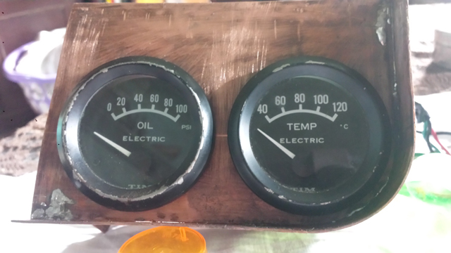 Rear View 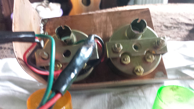 Good result and future images will be even better. | ||
Robert Noel Reddington Grand Master Username: bob_uk Post Number: 631 Registered: 5-2015 |
A picture paints a thousand words. The pod is now fitted to the car and looking good. I painted it black so I can see what it going to look like when trimmed in black leather. Gauges are 52mm dia. On top of the gauges is a small facia hopefully in walnut burr. | ||
Robert Noel Reddington Grand Master Username: bob_uk Post Number: 633 Registered: 5-2015 |
The Kienzil time clock will not work off of a PP9 battery. This clock is mechanical and is wound buy a solenoid about every minute. The current draw is simply to much plus 9v isnt enough. So thats that idea finished. However some clocks are analogue quartz and may work on a PP9. Just not mine. Still I have a wrist watch. | ||
Robert Noel Reddington Grand Master Username: bob_uk Post Number: 636 Registered: 5-2015 |
The gauge pod is now mounted with invisible fixings. The walnut centre consul is reinstated and looking good. The trim and walnut facia for the pod will have to wait because I have no glue or walnut veneer or ply to stick the walnut to. Plus to chamfer round holes I need to make a cone sanding drum. The bulb in the cruise control was normal white. So green LED inserted. These green LEDs are very green. I tried again to make a LED cluster red fog lamp bulb. This one is an improvement on my last effort. Is about as bright as 5w tail lamp. Which is useless for a red fog lamp. Proper LED clusters 382 bulbs are only 7 quid. Radio aerial. The original aerial works fine goes up and down etc. I have unplugged it from the radio and fitted a wire that dangles under the car. The radio works fine like this. However this may not be the case when the car is moving. The radio case is earth bonded to the transmission tunnel earth braid under the radio this makes the car a ground plane for radio signals. I was told many years ago that proper earth bonding of the radio case improves radio reception and the earth from the radio supply plug isn't good enough. Thankfully Crewe know this and fitted one. So simple nut and bolt job. I hate these electric aerials the pavlava of the aerial going up and down in case someone breaks it off is annoying. My Jeep has an auto matic one which is just as annoying. Next job is to check out the SU pumps again. Then back to ride height. Hopefully all the ride height now needs is a bleed out. And earth bonding check of cross member because of the fast solenoid. Photos to follow hopefully. I took some today but I need better lighting. The car is on stands in my man cave. | ||
Geoff Wootton Grand Master Username: dounraey Post Number: 991 Registered: 5-2012 |
Hi Bob I'd be careful about changing your external lights. In the UK (and probably the US also) it's a legal minefield. Some sources say it is just plain illegal to replace exterior bulbs on classic cars with LED lights. Other sources say it is more complicated than that. Since external lights are crucial safety devices there could also be problems with insurance, unless the mods are declared. Geoff | ||
Robert Noel Reddington Grand Master Username: bob_uk Post Number: 637 Registered: 5-2015 |
Yes I am aware that the regs say incandescence light bulbs and 100mm between filament centres. However it would only be a fix it note because the regs about fog lamps are not applied retrospectively unless a fog is fitted. The fog lamp looks like a reversing lamp. Fog lamps are not required on a 1974 car. So it would take a shinny buttons copper to even comment. In general if a car looks OK the cops don't start checking details and having worked for them only a hand full of traffic officers would actually know the lighting regs and apply the "well it works" rule. The insurance implications are that if the LED bulb causes an accident then the insurance company will be unhappy but they by law have to pay third party stuff. Good point about declaring to my insurers. I told them I diy fitted LPG and they didn't care because the number of LPG cars exploding is vitually nil in comparison to petrol fires. So I expect they will think I am trying to say my car is worth more. The yearly declaration includes space for new parts such as a rear bumper which I covert. A driver could be drawn into the bright red light like a moth and run into me. Apart from being over bright I cannot see any dangers. The incandescence bit is a bit vague and lots of cars now have LED exterior lighting. Where the Fuzz do get their nickers in a twist is younger drivers with blue lights on their cars. I saw a BMW with green lights all the way along the sills or rockers. It looked stupid and green means go, it could cause confusion from a distance. The rear fog lamp and instrument lighting and exterior lighting is about as far as I going LED wise. These will get my DIY bulbs as required. Warm White LEDs are rare buckshe as I have been doing with the coloured ones. I have blown a few LEDs up before the penny dropped on V =IR. The capacitors in the pumps wreaked half of them. Thing is by actually diying it and working through the errors does one start to fully understand the details I think I have solved the lighting problem. Turn the garage lights off so the camera uses its flash. I am a silly billy. | ||
Robert Noel Reddington Grand Master Username: bob_uk Post Number: 642 Registered: 5-2015 |
The pump points were faulty so cleaned the points with a light touch of the Dremel. Sorted. The pumps are easier to fit if the top holes in the rubber lined clamps are slotted and the 2 top bolts fitted first. 7/16 AF bolts 1/4 unf. The ride control is working fine and the rams bled out. 1/4 litre from each ram. The castor oil at 5% has been added. A sign of air in the hydraulic system is rhe warning lights coming on earlier when pumping down. Before I took the hydraulics apart the pump down was about 90 after assembly the pump down dropped to 60 and 30. After bleeding the pump down has increased to 80 and 50. There's still air in the system. Leave alone for a couple days to allow any froth to settle ( 1 hour would do but I can't be bothered at the moment) Today I went to get clearcoat for the wood but their computer stopped working so they couldn't sell me any. So I watched a film instead and fell asleep. I have cleaned and fed all the leather in the car I work it in using my hands. It took 3 hours. | ||
Robert Noel Reddington Grand Master Username: bob_uk Post Number: 654 Registered: 5-2015 |
Noticed after doing leather that my hands are soft and very clean. Leave the dusters used on leather in the car the duster gives off more leather smell. Electrics. I have 3 faults master cylinder warning light. Bonnet light. Mascot Alarm. The bonnet switch for the bonnet light appears to not have a long enough plunger. And stays on. The power for the mascot alarm comes from the bonnet light circuit. I can hear the micro switch making and breaking. The master cylinder switch is making and breaking so fault is between switch and light. It will be a dodgy connector somewhere. The bonnet light is a good place for LEDs. The wiring diagrams are a boon when fixing faults like the master warning light because the theoretical ones show the logic. And practical ones show exactly where the wires and plugs are on the car. The screws holding the bonnet light switch to the righthand bonnet hinge are 6BA. | ||
Mark Aldridge Prolific User Username: mark_aldridge Post Number: 266 Registered: 10-2008 |
Bob, if the bonnet switch is irreparable, RS Components do a long overthrow microswitch which can be fitted if you fabricate a bracket and works fine. My bonnet lights are LED. Mark | ||
Robert Noel Reddington Grand Master Username: bob_uk Post Number: 656 Registered: 5-2015 |
I have had a good look at the plunger and it doesn't appear to be broken. So far a bit of a mystery. I was getting tired so will have a good look to figure it out. The switch and light both work fine when switch manually operated. Access is awkward. Nearly every car I have had has had bonnet light trouble. A couple of under bonnet sockets like Land Rovers had on the dash board black and red would be handy for a lead lamp. The Crewe bonnet light is purely for checking engine oil level not serious work. Also the radio aerial. I have designed an aerial made from 14" of 3/8 copper tubing that is held to the sill using plastic P clips and the screws that hold the rat trap on. The wire is simply screwed to the copper. Hopefully the screws are long enough. Also changed a loudspeaker righ rear. The cone was becoming detached from the edge. A bit of silicone will fix it for later use. I have a few speakers lying around. My Jeep speakers are buggered as well. How many amps does your LED bonnet light consume. The standard 6w jobbie eats approx 500 ma or 1/2 amp. Not a lot I suppose. But any higher wattage and the plastic lens could melt. So brighter LED is really the point. | ||
David Gore Moderator Username: david_gore Post Number: 1770 Registered: 4-2003 |
More images from Robert [Bob] - these are test images to get the right parameters for taking photos in Bob's workshop so quality is variable: Bob's lathe as mentioned in his posts:  Bob's reservoir. The red smear on the caps is rubber grease to seal the vents: 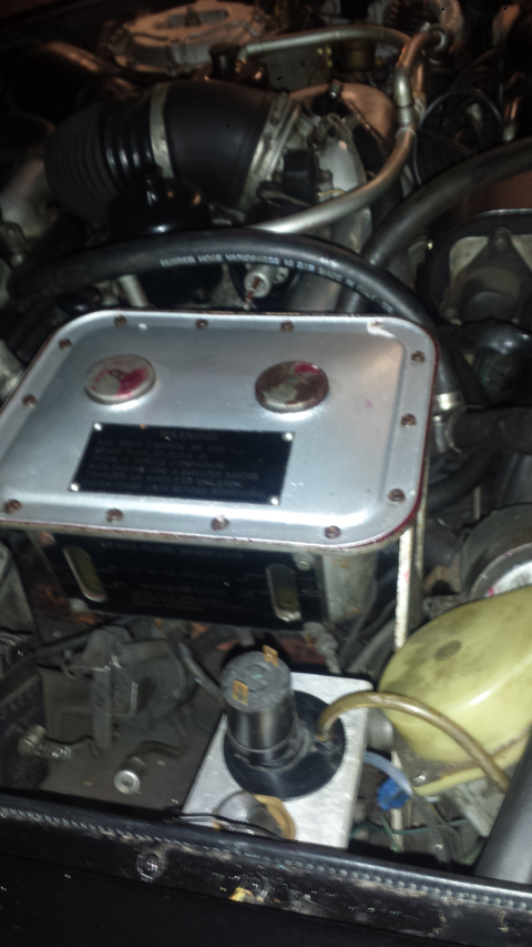 Bob's screen wash pump and filler. Just underneath is a yellow pipe which goes to the bottle hidden behind the inner plastic mud guard: 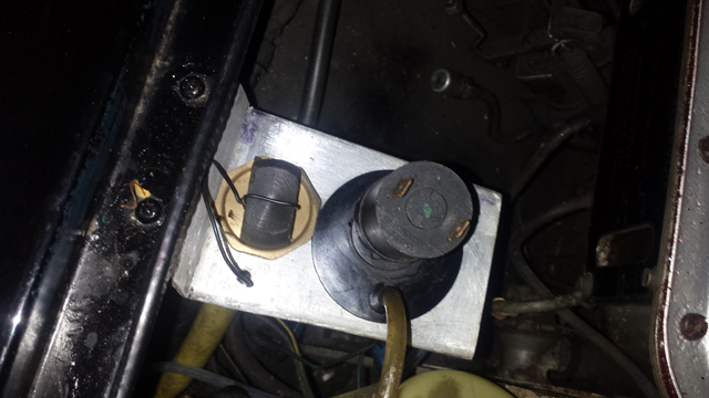 Removal of rat trap from underside of car: 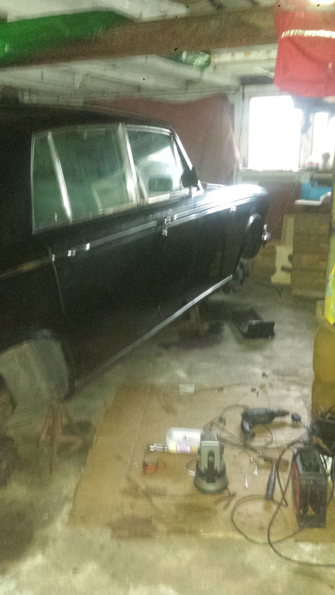 | ||
David Gore Moderator Username: david_gore Post Number: 1771 Registered: 4-2003 |
The following are links to test audio-visual files showing parts of the dashboard in Bob's Shadow - this is unedited raw vision only: https://drive.google.com/file/d/0B9mUh6PYLo-Rc2FfRHdUbDVCV1k/view?usp=sharing https://drive.google.com/file/d/0B9mUh6PYLo-RMTA2UUpZUTVNWEE/view?usp=sharing | ||
Robert Noel Reddington Grand Master Username: bob_uk Post Number: 657 Registered: 5-2015 |
I like the photos Dave. They came out ok. Today I researched the logic behind the master cylinder over travel warning light. The circuit is earthed switched. So first check is earth the bulb side of the switch if the light lights then the fault is either switch or earth. Hopefully its the earth gone awol. I dread changing the switch. Really needs an inspection hatch in the floor to get at it. So if anybody is repairing a rusty floor now your chance to fit an inspection panel above the rat trap. I would use at least 16swg steel with radius corners and hank nuts to secure 1/4UNF bolts. Like the lower seat belt mounting. Make it so it looks like its meant to be there. I didn't actually do anything to the car today because Whiskey Galore 1949 film was on and its Halloween. Tomorrow Sunday I will take some more photos. I checked out my home made LED from 75 feet and its brighter than the tail light so it does sort of work. Needs to be a bit brighter. I shall change the resistor for a lower ohms to allow more electric through. Despite 41 years old the electrics on my car are in good shape. Lucas CAV made the bits but the actual wiring looms were made by Crewe using brass connectors and quality wire made by Rists. The only problems I have had is behind the foot wheel kick panels. Here connectors have given trouble. I have used choc blocks to solve problems. Although choc blocks seem bodgy they actually work quite well. Use only brass ones and use small as possible ones. A refinement is to tin the wire with solder, but plaque on the wire needs to be removed first. Choc blocks never give trouble and are not unlike connectors used on older Royces. Black ones are available. | ||
Geoff Wootton Grand Master Username: dounraey Post Number: 998 Registered: 5-2012 |
Bob Thanks for the pics - also to David for putting them up. I'm impressed with how the reservoir lid has turned out. Normally when it's painted it looks, for want of a better word, painted. Yours is a very close match to the original cadmium plated lid. It does occur to me though that this is not a diy solution for the rest of us, as the paint used has to be sprayed in a special paint booth. Very useful you were able to get this done for free. Geoff | ||
Robert Noel Reddington Grand Master Username: bob_uk Post Number: 660 Registered: 5-2015 |
I am pleased with the lid of the tank. The paint used was Imron type paint. Note this stuff must not be used DIY. It either kills or damages the nervous system. And just a little bit is enough to do the damage. I read about a guy who used some on suspension bits and he turned into a vegetable. Just a repeat warning. The master cylinder warning lamp fault is proving difficult to find. The loom goes into another loom then forward to a right hand toe board plug and socket but which one and which terminal. The wiring is cotton covered and grease has obscured the colours. Brake cleaner hopefully will clean enough to id the colours. Wiping with rags will just drive the grease into the cotton. Whilst changing a loud speaker one of those blue crimp on connectors fell off. Can't beat a properly soldered joint. With speakers I like to solder tails onto the speaker terminals. Clamp the tails to the speaker frame. Then solder male spades to the tails. Plug in with a dollop of petroleum jelly, last for ever. The bonnet light does actually go out when the bonnet is shut but only just. There appears to be no adjustment possible. Limited access makes inspection such a pain. Ideally light off with bonnet half way down. The mascot alarm is simple, one of the wires to the switch has fallen off. Use warning highlighted by Moderator. | ||
David Gore Moderator Username: david_gore Post Number: 1772 Registered: 4-2003 |
Bob, Have you thought about mounting a mercury switch on the bonnet and adjusting it with a wedge to go open circuit when the bonnet is half-closed?? http://www.jaycar.com.au/Electromechanical-Components/Switches/Other-Switches/Mini-Mercury-Switch-SPST/p/SM1044 http://www.jaycar.com.au/Electromechanical-Components/Switches/Other-Switches/SPST-Mercury-Switch/p/SM1035 | ||
Robert Noel Reddington Grand Master Username: bob_uk Post Number: 661 Registered: 5-2015 |
Mercury switch good idea. But first I shall a good look at the present set up because surely it didn't leave Crewe like this. The bonnet light was disconnected when I first got the car. And the other day was the first time in 26 years that the bonnet lamp came on I was surprised that the bulb still worked. | ||
Robert Noel Reddington Grand Master Username: bob_uk Post Number: 662 Registered: 5-2015 |
The mascot alarm now works 15 secs of the QE 2 docking at Southampton. It turns out that when the car was repaired after a stupid MOT tester mistook the gear lever for indicators with engine running and hsnd brake off. The body shop monkeys disconnected it on purpose because it wasn't adjusted correctly. Why oh why they can't get small details right. I suspect that they didn't bench test the adjustment. And didn't want to take the Rad shell back off. The bonnet light. The switch is an absolute PITA to remove. The plunger is just too short. So I put a crimp on blue female bullet on top not crimped but held on with sticky thick grease. The lamp retires when the bonnet is about 20 degrees from horizontal. Super dooper. The alternator charging booster thingy. When I removed the regulator I found that the voltage reference connection was on medium, so I reconnected to high. At a rev I now have 14.45 volts. Which is 5 hundreds of a volt over battery gassing. So bang on the money. At idle 13.98 volts. Which is also good. Incidently I got 18v at first. Which is very bad and will wreak the electrics eventually. The battery in the multi meter was low. So I checked with my mains multi meter and the readings were as above. I changed the battery in the little multi meter and it now reads correct. I didn't realise that a low battery would cause incorrect readings. Electrically all that is left is the master warn light and conversion to head lamo flash dipping. The floor switch is jammed and now doesn't switch. What a rip off that switch was �4 new from Lucas and only lasted 20 years. VW up until 1979 used a relay for this very purpose on Beetles and Golfs and aircooled vans. It is still available. Part number VW Audi. 111-941-583. About 30 squids. Or cheaper from Beetle shops at 20 squids. Or cheaper still from junk yard. Made by Hella. | ||
Bob Reynolds Grand Master Username: bobreynolds Post Number: 344 Registered: 8-2012 |
I had no end of trouble with my bonnet light switch. It's just about impossible to get 2 hands in to it, and the nuts were completely corroded on, so that the whole lot went round when I tried to undo the bolts. After I got it off, the small brass terminals were stuck solid and wouldn't budge (the wires fell off years ago) and the internals of the switch were a complete mess and not repairable. It's a very crude design of switch. Flying Spares wanted a silly amount for a used switch, so I just used an ordinary microswitch fixed on to a simple bracket, and it works very well. The hardest part was adjusting it. The microswitch may not be waterproof, but judging by the state of the original, that wasn't waterproof either! I didn't think about using a tilt switch, but I'm not sure that would be a good idea as it may operate when the car is in motion or going downhill! A magnet and reed switch would be better (switch fixed to the car, magnet fixed to the bonnet hinge) and the switch could be positioned in the same place as the original. | ||
Robert Noel Reddington Grand Master Username: bob_uk Post Number: 665 Registered: 5-2015 |
The screws are 6 BA. Stupid small. I wouldn't worry too much about the light comming on when going down hill if using a tilt switch, after all the engine running and 6 watts or 1/2 amp isn't going to hurt. But what about parking down hill. The magnetic reed idea is good because the adjustment is easier and its a sealed unit. Same as a mercury switch which can't wear out. Or a manual switch under the bonnet. The bonnet light took ages to fix. Which because of labour charges don't get fixed by garages unless the owner specifically asks. Mind you I faff about a lot and half way through a job I will decide to tidy up while I think through the problem. Rear Springs. I am taking the rear springs out because the bottom cups appear to have a bit of canvas rubber where it shouldn't be. The check strap bolts are 1/2 UNF with 3/4 AF head. The nuts are brazed to the pan under the rear seat and can be accessed from the top inside the car. My right hand strap bolt was quite tight. The left hand one was much easier. These bolts don't need to be very tight. All they do is stop the suspension dropping too far when jacking car up or when flying off hump back bridges. 35 ftlbs is enough. Another medthod of checking the suspension is to use a chain instead of a strap. I prefer a chain wrapped in leather. Much easier than RR design. I have used this method on trucks it works well and is easy to dismantle any problems cut the chain and fit new one. However I shall fit the solid straps back as the were. The straps are spring steel with a rubber lining. The lining on mine is rotted out and covered in grease. Horrible yucky mixture of grease, road dirt and rotted rubber. In the workshop manual to adjust the rear standing height its ok to lift the spring and slip shims in. The shims are simply big washers made from 18 swg steel. I can turn 18swg washers on my lathe but 1/8 steel much easier. Note the drive shafts, valve linkages, lower damper nuts and check straps still need to be disconnected when lifting the springs. I think I might as well go the extra 5 min step and take the spring out. I am also thinking how can I make an adjustable shim that can be adjusted with out any dismantling. I am think jacking bolts pressing a thick shim in the bottom cup up wards. But room is tight because RR say max of 7 shims in bottom cup. 18 swg is 0.048". Thats 0.350" max. So a jacking shim needs to be no thicker than 1/4". If I could remove the trailing arm to the bench I could weld special nuts to the cup. But I am thinking about a another shim with 4 threaded holes and a thiner Jacking shim. 1/2 UNF threads should be strong enough. The spring is not captivity bolted in so using to much depth of the cup is dodgy I have seen coil springs jump out of cups and bugger the damper rod and on the front I saw a coil spring that had ripped the tyre off the rim. Boy racer lowered car with cut springs which is a no no. Once I have all the gubbins out I shall post photos and also measure up for my jacking shims and see if its feasible. | ||
richard george yeaman Grand Master Username: richyrich Post Number: 389 Registered: 4-2012 |
Hi Bob The canvas rubber thing you refer to is to keep the spring and the cup it sits in from making a noise and if removed needs to be replaced with todays equivalent. Richard. | ||
Robert Noel Reddington Grand Master Username: bob_uk Post Number: 666 Registered: 5-2015 |
I have got the right rear spring out. Apart from the check strap all the bolts for hand brake, drive shaft, valve linkage, bottom damper nuts and the 1/4 UNF bolts all came out with little fuss. The bottom isolator is tatty and has a split. The top is intact. The shims under the bottom isolator have crumbled to rusty scale. There are no top shims fitted. The shock damper has a white band and the gaiter is in good condition a steering rack gaiter would fit. So thats a cheap option for cars with dodgy damper boots. The white band is for non colonial cars. Colonial cars might have yellow bands and harder springs. The actual cup welded to the trailing arm has surface rust only with q bit of pitting inside the cup. I have bashed it around with a club hammer and its sound and fit for service. I measured up and the isolator and scabby shim are 1/4" so plenty of room for adjustment plus the top has no shims. This job is a must because of the amount of muck in the bottom cup. If ignored then the cup could rot out. This bit is available but has to be welded to the trailing arm. All the welds are critical and must be done using proper welding technics like argon and tig. It could be done on the car. But is bound to be not cheap. The idea of jacking bolts and shims won't work there's not enough room. And besides if the standard way lasts 100k miles then thats good enough. There's not enough meat around the 1/4 UNF threads that hold the damper cup to the spring cup. 1/4 is not strong enough to jack with. They need to be at least 3/8. | ||
Geoff Wootton Grand Master Username: dounraey Post Number: 999 Registered: 5-2012 |
Bob You mention the lower spring isolator is tatty and has a split. How are you going to replace it. FS sell them for 50 ukp each. Are you going to make your own? Geoff | ||
Robert Noel Reddington Grand Master Username: bob_uk Post Number: 668 Registered: 5-2015 |
At 50 quid each I am going to make them. Materials. Rubber is the obvious choice. Others are urethane or wood both of which can be easily machined. Rubber is a bitch to machine. Urethane can be mixed up and poured into a mould made from whatever probably wood. The problem with wood is that close grained wood such as ash is also hard and also like steel in this application. Not sure of how it wood (pun intended) feel. Another very attractive option is Grayston towing assisters GE 14.These are about 15 quid a pair. I happen to have these fitted between the coils. I could fit then to the end of the spring. The front springs use GE 13. These are too short and would leave a gap not good. Also pet shop sell rubber rings for dogs to play with. Plat strips of inner tube into a ring. While I remember the bolts for the drive shaft are 7/16 UNF with 5/8 AF bolt head. The damper nuts are 11/16 AF thread unknown. Might be metric. Tomorrow I shall clean the table up set up and photo the bits. In tee one topics Bill Coburn described a method of holding damper rods in. I shall take a photo of the method. | ||
Robert Noel Reddington Grand Master Username: bob_uk Post Number: 670 Registered: 5-2015 |
The rear suspension is now back together. I made an isolator from polypropylene rope fused together with heat. I have just sent the photos to Dave. | ||
David Gore Moderator Username: david_gore Post Number: 1773 Registered: 4-2003 |
More images from Robert: This is Bill Coburns method of retaining the shock damper ram: 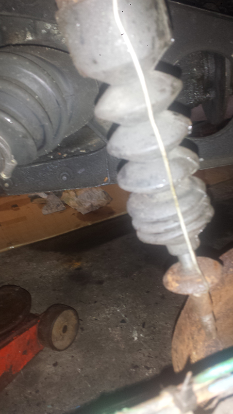 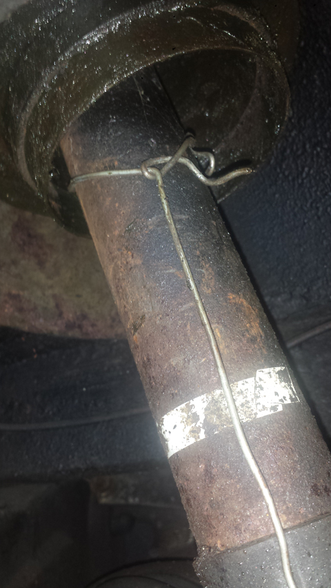 | ||
David Gore Moderator Username: david_gore Post Number: 1774 Registered: 4-2003 |
These are Grayston assister "thingys". The big one is GE 14 and rear the small one is GE 13 and front. 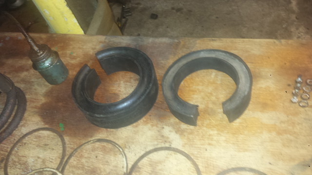 | ||
David Gore Moderator Username: david_gore Post Number: 1775 Registered: 4-2003 |
Shims. These I found stuck up the top. So shims were fitted. I just didn't see them at first. The top right corner is the nuts and bolts: 4 damper cup, 4 drive shaft, 2 damper nuts. 2 not shown are for hand brake cable clamp. 12 in all. Not a lot to take off. 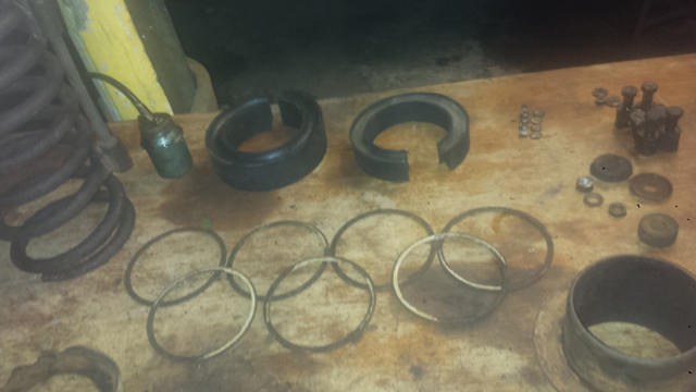 | ||
David Gore Moderator Username: david_gore Post Number: 1776 Registered: 4-2003 |
The blue thing is my home made isolater. It is polypropylene rope coiled and fused with heat. 20 mm thick. 2 layers of 10mm rope 4 coils wide. The bottom one is the top and in good condition. The other one is the tatty bottom one. 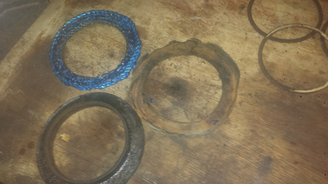 | ||
David Gore Moderator Username: david_gore Post Number: 1777 Registered: 4-2003 |
Here is the spring which is quite heavy. The clamps are at their design limit. Not to happy with this. On the other side I will borrow a pair of heavy duty ones. Moderator comment: Bob, did you use these compressors whilst removing the springs? I would have been very nervous about using ordinary spring compressors and as I have a set of heavy duty 4WD compressors, these most likely would have been used as the front springs were about to be replaced on DRH14434. 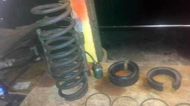 | ||
Robert Noel Reddington Grand Master Username: bob_uk Post Number: 671 Registered: 5-2015 |
I compressed the suspension on the car then fitted the clamps over 6 coils. Then tightened the nuts so that thread was fully through. I put about 40 lbs of torque on the nuts. I didn't use the clamp to compress just to hold it. Then slowly dropped the arm. I agree this was risky but I got away with it. The other side I will borrow a set Sykes Picavant heavy duty ones. I am pleased with my home made isolater. After I fused the rope a bit at a time with a pencil blow lamp I warmed the whole lot with a heat gun. I used the top spring mounting as a mould. I pulled it around after and its quite strong. Thermo plastic plastic. One of the damper cup bolts had been cut down from a longer bolt making me think that this lot has been apart before. Making shapes by fusing polypropylene rope together has given me other ideas. Such as tyres for my cement mixer which have rotted out. The tyres are not used on the road merely around the garden. Note if the isolater goes wrong its not dangerous. The suspension won't fall out. In any case the ram will correct it. And I am back to square one. Under compression polypropylene is quite strong under tension its about as strong as rope. I always apply what if to things I make. | ||
Robert Noel Reddington Grand Master Username: bob_uk Post Number: 718 Registered: 5-2015 |
The other side rear suspension has also now been reshimed. The job wasn't bad to do. Today I re lacquered the drivers door wood. Unfortunately I over did it and got a sag. From experience the best thomg yo do is allow to dry for 24 hours and wet and dry paper and re spray. Funny thing us that after a couple of hours the sag looked not so pronounced. Its strange how mistakes seem very bad at the time but later not so bad. The mind plays tricks like this. | ||
Robert Noel Reddington Grand Master Username: bob_uk Post Number: 773 Registered: 5-2015 |
I have removed the engine drain plugs. 15/16 AF socket size. Both sides are clean and clear. The coolant was blue and clean. I will just do a simple garden hose flush to remove all old antifreeze. The coolant being clean and no blockages at the drain plug is a good sign that the engine coolant jacket is not scaled up. Cock up. I re fitted the left hand rear door trim card and forgot to connect the lock plunger. So it has to come off to put right. Oh well. | ||
Robert Noel Reddington Grand Master Username: bob_uk Post Number: 778 Registered: 5-2015 |
I have started the rust proofing process. This is a dirty mucky job but its a must do job. It will take 1/2 a day. I am using a mix of wax oil, bitumen based underseal, grease, engine oil and something for girls a spot of ATF. Another cock up. This time I fitted the other side door card and connected the courtesy light to the live for the cigar lighter and the live for the courtesy light. 2 lives don't work. Oh well. | ||
Robert Noel Reddington Grand Master Username: bob_uk Post Number: 1054 Registered: 5-2015 |
Early on in this epic I fitted LED lights to the fuel pumps to show they are working. This is a stupid idea and is going to be removed . Easier would be to rewire the pumps so that I can simply disconnect each pump in turn to check it. Also the aux amp for a MP3 player isn't very good more like awful. So that's going as well. | ||
Patrick Ryan Grand Master Username: patrick_r Post Number: 349 Registered: 4-2016 |
Seems the old girl only likes old tech Robert. That's not a bad thing. | ||
Robert Noel Reddington Grand Master Username: bob_uk Post Number: 1056 Registered: 5-2015 |
The pump warning lights were fitted by me while I was suffering a bit of dementia. I got over complicated. Besides I use LPG and if one pump fails the car still runs and su pumps are reliable. At the moment the power supply goes to one pump then the other which is why I can't isolate a pump. If I rewire so that the power is split before the pumps then I can isolate a pump to check. The top holes of the pump brackets are slotted so I can get the pumps off in 5 mins and refit in 10 mins. I forgot the kiss motto keep it simple stupid. The MP3 aux amp is useless, fortunately I got it for nothing. The only mod I will keep is a warning light that tells when the fast ride solenoid is on. When these mods were done I didn't cut any original parts around so is at 5 min job to remove at no cost. The only bit that will be kept is the LPG control module. Once I have decorated my hall at home and serviced the rear axle and brakes on my jeep I will be back on the Shadow. The Shadow has had a big service and I have checked about every thing there is to check. Next stage is a complete electrical check. Which won't take long. Then its on to the body work. I have measured the surface area of the paint defects and it's about the size of A4 total. I have black paint, etch primer high build primer and clear coat in stock. All I need is 5 litres of standard cellulose thinners and a litre of slow thinners. I will probably use a smear of bondo here and there to get things just right. My car was originally peacock blue. Painting the car black has devalued the car. But to make the car RR standard it needs a bare metal respray. So to return it to as new just paint it peacock blue. A bare metal respray is a lot of work and it takes 40 hours of hard work to prep the car. At �40 an hour that's 1600 quid. To spray the car is about two hours. 10 hours to polish and then 10 hours to reassemble. About �2500 plus tax. Call it �3000. I can strip and prep the car but the paint needs to be 2 pack and baking in the oven. Because when the car is on the road I intend to use it as a run around then I will stay with the much cheaper option on small area repair. The car is tax exempt and can now be fitted with black and white number plates which will look good on a black car. However I have noticed that black is a popular colour on any car and they seem to sell easier. But I am not selling the car so I can suit myself. Black has a reputation for showing up defects and some try to avoid black. But to me it's a plus point because it makes defects stick out like a sore thumb thus making it easier to repair you know when it's right straight away. Plus black is so easy to spray and blends well. Clear coat makes it like glass. One could use my doors as shaving mirrors. Restoration and conservation. My qualifications say restoration and conservation. The work is more about conservation than full blown restoration. The conservation bit is often overlooked and some cars can be like old guns devalued by restoration. A bit like buying the Queens Rover P5B and retriming it. The Queen has sat in the seat and it's been thrown away. Health permitting. |