| Author | Message | ||
Geoff Wootton Grand Master Username: dounraey Post Number: 714 Registered: 5-2012 |
Hi Folks I am currently reconditioning my carbs and have a question about the accelerator linkage. I include a pic of the carb assembly on my workbench to give context to the pics that follow. 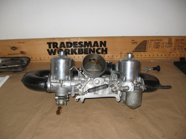 The part I want to discuss, the coupling link, is arrowed in the following picture 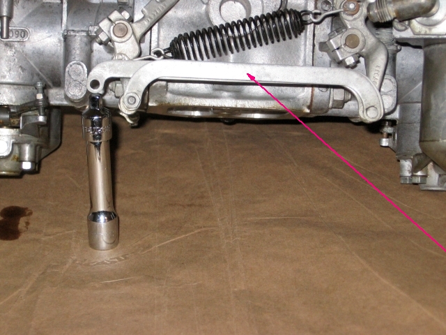 This link connects the two throttle butterfly valves through the throttle levers. At the left hand end of the link is a nut. One would presume it is there simply to fasten the link to it's pivot. However, this is only part of the story. On removing the nut and dropping the lever there is a non too obvious cam. The next two pictures show the cam in it's highest and lowest positions. 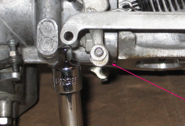 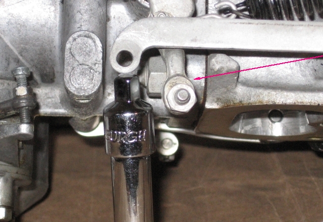 When the carb assembly is fitted to the engine there is very little clearance between the coupling link and the top of the inlet manifold. If the cam is set to it's lowest position the coupling link actually fouls the manifold. The only logical position for this cam is at it's highest point to give sufficient clearance. Any lower and you risk at best a rough accelerator action as the link grinds on the manifold and at worst an unwanted throttle stop. So why is the cam there? Since the cam has only one logical position (the highest) why didn't RR just "drill the hole in the right place". The only reason I can think of is they manufactured thousands of these coupling links before discovering the error. I'm speculating the cam was introduced as a bodge to save them having to re-manufacture the parts. Has anyone any info on this or seen this cam documented anywhere? Regards Geoff | ||
Chris Browne Prolific User Username: chrisb Post Number: 210 Registered: 2-2010 |
Hi Geoff, What you are referring to is an eccentric pin the purpose of which is to enable the carburettors to be balanced. If you loosen the locknut and turn the eccentric slightly in either direction, you lengthen or shorten the effective length of the cross link. When it is adjusted correctly, it enables both throttle butterflies to open simultaneously. If it is wrongly adjusted, one butterfly will open before the other causing an imbalance. Hope this helps. Kind regards, Chris | ||
Geoff Wootton Grand Master Username: dounraey Post Number: 715 Registered: 5-2012 |
Hi Chris Thanks for that explanation and also for the correct nomenclature. I hereby withdraw my accusation that the eccentric pin was used as a bodge. I should mention however, for anyone reading this and about to dismantle their carbs, that this method of setting the synchronization of the throttles is not documented. See page K19 of the SY1 workshop manual, where the alternate method of holding the butterfly valves closed and tightening the spindle clamps is described. It is important to be aware of this pin, as incorrectly adjusted, the coupling link will foul the intake manifold. Regards Geoff | ||
Chris Browne Prolific User Username: chrisb Post Number: 211 Registered: 2-2010 |
Hi Geoff, The process is documented in the Shadow 2 workshop manual (TSD4200)in Section K5 page 31 under the heading "Carburettor idle air balance". After having fitted dial test gauges to the carburettor dashpots in place of the damper pistons, the relevant paragraph reads - "Start and run the engine at the idle speed setting (650 rpm); adjust the carburettor piston lifts to be equal (within 10%) using eccentric adjuster (see Fig. K97)which is in Section K7 page 1. Hope this helps. Kind regards, Chris | ||
Bob of Dorset Unregistered guest Posted From: 188.29.164.117 |
To balance butterflies I use paper between the butterfly and carb wall. I adjust so that the paper slides with a bit of grab like feeler gauges. I gradually turn in the throttle stop until one of the bits of paper slips. Then try the other one. At idle and just above the butterflies need to be in unison. At larger throttle openings near enough is good enough and 2 degrees out of balance will not be detectable. So concentrate on the idle position. On some cars like Truimph 2000 automatic. When on idle the butterflies are in balance. As the throttle is opened on butterfly on front carb opens a small amount before the other. It leads the rear carb. This is to stop the abrupt 0 to 2mph surge. Once underway the very slight imbalance isnt noticed. So when setting up it doesnt have to that accurate. Dial test indicators are going a bit over board. To set up a Suzuki RG 500 4 DTIs are used. Very complicated get it wrong and the engine could hole a piston. RRs are much more forgiving that. (Message approved by david_gore) | ||
Bob Reynolds Prolific User Username: bobreynolds Post Number: 257 Registered: 8-2012 |
This is very intriguing. I hadn't noticed that eccentric on there before. It looks like over-complication to me. Surely it's just as effective, and probably easier, to loosen the pinch bolts and rotate the throttle spindles. This is what everybody seems to do. Yes, dial gauges are more accurate than is required for balancing, but I use this method because it can be done very quickly and without any dismantling. Just unscrew the dashpot caps and stick the gauges in. It's accurate and there's no ambiquity, unlike trying to listen down a tube for sound levels! I don't know of any other method that is so accurate and convenient. These gauges can be bought very cheaply from ebay, and I bought 2 which I keep set up specifically for this job. They were much cheaper than buying an airflow meter! 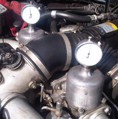 | ||
Geoff Wootton Grand Master Username: dounraey Post Number: 716 Registered: 5-2012 |
Bob Yes, I find this intriguing also. I've checked The SY2 manual that Chris pointed me to and the eccentric pin is fully documented and used to balance the carbs. However, if you look at Figure K97 the SY2 linkage is different to the SY1. The coupling link is mounted diagonally with the eccentric pin at the top, allowing plenty of clearance. I suspect also the pin is much more accessible for adjustment than on the SY1. It occurs to me that when the Engineers documented balancing the throttle butterflys' on the SY1 they realised clearance was very tight, so chose the alternate method most of us use. I can say for sure that if the eccentric pin is set at the 6 o'clock position the coupling link will foul the top of the inlet manifold on the SY1. I know this as I tested it yesterday. The carb assembly would not seat properly as the coupling link was pushing against the inlet manifold. I would have been able to tighten the assembly down, using the long central bolt, however this would have pushed the throttle valves slightly open. In effect the coupling link would have been acting as a throttle stop. I do not know if there is enough clearance if the pin is set at the 3 or 9 o'clock positions as I did not do that test. At 12 o'clock, there is about 1/8" clearance. I figured, given the "throw" of the pin was about 1/4", the 3 or 9 o'clock positions would result in the link just touching the manifold. Any lower, and you are opening the throttle valves. I think it is important we SY1 owners are aware of this eccentric pin. It is just not obvious at all when leaning across the engine and looking at it from above. It would be so easy to mistake it for a simple pivot pin. Bob - I really like your set up. I use a unisyn carbalancer which is very effective, however it is a pain removing the air ducting, particularly as the bolts than fasten it to the carbs are so difficult to access. So much easier to just remove the piston dampers and fit the dial test indicators. Also, your method is more accurate. I have found a company that sell the adapters for $50, so I may well invest in them. Many thanks to all the posters on this topic. It has really been most helpful Regards Geoff | ||
Bob Reynolds Prolific User Username: bobreynolds Post Number: 258 Registered: 8-2012 |
I just checked my throttle linkage, and yes you are right to bring this to our attention. There is no way that you would use this pin to balance the throttle butterflies in preference to the throttle spindle pinch bolts. It requires removing the air trunking, and even then would be extremely fiddly, requiring 2 spanners, 4 hands and a pair of pliers. And I suspect that after you had tightened everything up, it would need adjusting again! But on visual inspection it occurred to me that you might be able to position this eccentric pin further away from the manifold by re-adjustment of both throttle spindle positions and screwing the idle screw a bit further in. If you slacken off both pinch bolts, it looks like you could move that eccentric pin further away from the manifold, then tighten the pinch bolts up again. The idle stop would then be in a different position, but that can be re-adjusted. I haven't tried this adjustment, as I don't want to disturb anything. I might be completely wrong. My eccentric pin is around the 4 o'clock position, but there is quite a bit of clearance between it and the manifold. But the potential for fouling is very real and probably wouldn't be spotted. | ||
Geoff Wootton Grand Master Username: dounraey Post Number: 718 Registered: 5-2012 |
But on visual inspection it occurred to me that you might be able to position this eccentric pin further away from the manifold by re-adjustment of both throttle spindle positions and screwing the idle screw a bit further in. I agree. Taking the worst case scenario of the coupling link resting on the manifold holding the throttle valves open, once the clamps have been released, the valves closed and the clamps re-tightened then it is only necessary to turn the idle screw a couple of turns to obtain the necessary clearance. One could argue this is a compensatory mechanism to overcome an "incorrectly" set eccentric pin, however in practice, I doubt it makes any difference. It is clear to me now that RR engineers originally intended to use the eccentric pin as their method for setting the throttle balance. After all, they use it on the later models with the updated throttle linkage. It seems to me, for reasons of access and clearance of the coupling link/manifold they decided to use and document the spindle clamp method on the earlier SY1 models. Geoff | ||
Robert Noel Reddington New User Username: bob_uk Post Number: 4 Registered: 5-2015 |
Loosening the clamp and adjusting won't work as well as the eccentric. Every time the clamp is re tightened the bugger will move. There's nothing wrong with the design. The DTIs down the dashpot damper dont measure the butterflies direct. However all things being equal the amount of piston lift will give a clue as to balance of the buggerflies | ||
Bob Reynolds Prolific User Username: bobreynolds Post Number: 260 Registered: 8-2012 |
It won't move, because you are holding the valve closed with your finger. One hand on the butterfly and the other tightening the screw. I can't begin to imagine the difficulty of doing it the other way. The dial gauges don't measure the butterfly openings. The butterflies are synchronised by holdng them both closed and tightening the clamps, so they are bound to be synchronised. What the dial gauges do is to measure the airflow through each carb, so that you can synchronise the volume screws. (As I understand it.) | ||
Robert Noel Reddington New User Username: bob_uk Post Number: 6 Registered: 5-2015 |
Most in line twin carbs set ups have a adjustor screw in the middle for buggerfly balance. I shall try out the dti down the dash pot method. I problem with the Shadow set up is the air horns and the carb flange bolts. They are awkward. However the complete set up can be removed by the centre long bolt, butterflies set up then the carbs refitted. I checked my car this way when I serviced the carbs in 1989 and the balance was correct. Providing the adjustments havent been maladjusted then it should be correct and stay that way. Carb adjustors seem to attract tinkering by the unskilled when the car runs rough due to other faults. My horns are silver not black. 1974. | ||
Geoff Wootton Grand Master Username: dounraey Post Number: 719 Registered: 5-2012 |
Bob There's nothing wrong with the design. Then why did they re-design it. However the complete set up can be removed by the centre long bolt, butterflies set up then the carbs refitted. Only if the eccentric pin is positioned so the coupling link won't touch the manifold when the assembly is refitted. Here's a photo to show the amount of clearance between the coupling link and the manifold. The width of the link is 3/8", so you can estimate the size of the gap - 1/32" perhaps? This is with the eccentric pin adjusted high. 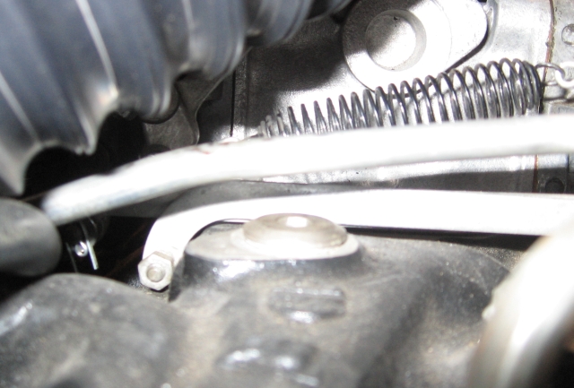 Geoff | ||
Robert Noel Reddington New User Username: bob_uk Post Number: 8 Registered: 5-2015 |
My linkage isnt that close. Is the correct gasket fitted to the centre bolt bit?. Fitting a thicker gasket will lift the linkage up a bit. | ||
Bob Reynolds Prolific User Username: bobreynolds Post Number: 261 Registered: 8-2012 |
" I have found a company that sell the adapters for $50, so I may well invest in them." That sounds a bit much to me, I would expect to get the gauges as well for that! I made the adapters up on a cheap Chinese lathe in a few minutes. You just need to make two collars that are a snug fit in the neck of the carbs, and sit on the top. Drill a hole through the centre for the gauge to pass through, and clamp it with a grub screw. The probe of the gauge is extended by a 3.75" rod that is attached by a short piece of plastic tubing. This is simple and provides a flexible connection. I found that you do not actually need to thread the collars so that they screw into the necks of the carbs. This makes the construction MUCH simpler. The weight of the dial gauge assembly is enough to hold it in place, and the gauges can just be dropped into position. The only problem with this is that the gauges can shake about slightly if the idle is not perfectly smooth, but you just need to hold the collar down onto the carb whilst taking the reading. Drop the gauges in and make sure they are touching the bottom. Zero them by rotating the dials. Adjust the Volume screw of the carb with the lowest reading to bring it up to the other one. I found typical readings to be 1.2mm lift at 600 RPM and 1.5mm at 800 RPM, so the piston movement is only very small, but that is more than a complete revolution of the dial, so any differences between the carbs are easily spotted, and you can adjust the screws to get them spot-on the same. Always tap the suction chamber with a screwdriver handle before taking a reading, to settle the piston. This looks like an expensive set-up, but there are lots of suitable dial gauges on ebay for only �5! And you also get a plastic case as well which you can throw away! Search for Dial Test Gauge. 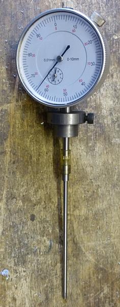 Hope this is useful. | ||
Geoff Wootton Grand Master Username: dounraey Post Number: 720 Registered: 5-2012 |
Hi Robert A thicker gasket would work, but I am now comfortable with how to proceed. Bob R cracked it by saying this lack of clearance between the coupling link and manifold can be adjusted out. Imagine a situation where the idling screw is fully backed off and, for the sake of argument, the coupling link is resting on the manifold. It is only necessary for the idler screw to be screwed down against it's landing + a couple of turns and the link/manifold clearance has been made. I suspect most SY1 owners are not even aware of this eccentric pin, whatever it's position, as it is automatically corrected by adjusting the idling screw down. The only problem, is when you carry out the setup with the carb assembly on the workbench. If by chance you adjust the eccentric pin so it is at or near the 6 o'clock position, when you put the assembly back on the engine your settings will be altered by the coupling link touching the manifold and have to go through the whole setup procedure again to adjust in some clearance. I fully accept this situation may be anomalous to my car, but I can't think why. Everything seems standard. In any case, I now understand the issues so can proceed with the rebuild of my carbs. Bob R - I have often been very tempted to buy a small benchtop lathe, but sadly my use of it would be too minimal to justify it. Thanks for putting up the info. I will be checking ebay for a similar set of gauges/adapters. PS - What's happened to Bob_UK - I haven't seen him on the forum for a few days. Geoff | ||
Brian Vogel Grand Master Username: guyslp Post Number: 1327 Registered: 6-2009 |
Geoff, Bob UK is Robert Noel Reddington. He registered as a "real user" and note, his user name is bob_uk. He was also "Bob of Dorset" for about a day during the transition period. I mentioned on another thread that the number of monikers that Bob UK went through in less than 48 hours was making my head spin. At least all is settled out now. Brian | ||
Bob of dorset Unregistered guest Posted From: 188.29.165.247 |
I am bob uk and bob of dorset and Robert Noel Reddington. Sorry about the confusion, my fault. I can be a total duffer on computers despite have 8 City and Guilds qualifications in AutoCad. The answer to the eccentric pin is don't adjust to the 6 o'clock position. Use the noon position. When I got my car in 1989 I fitted needle jet and float valve bits. I checked the butterfly balance at the same time. It was fine so I left it alone. The throttle idle stop has never been touched in 26 plus years My car 1974 has no throttle damper no kickdown or Aircon thingy. So is about as simple as it gets. The kick down is under the pedal inside the car. Just had error message about using Bob UK. (Message approved by david_gore) | ||
David Gore Moderator Username: david_gore Post Number: 1624 Registered: 4-2003 |
Hi Bob, There is a way you might be able to recover your Bob UK membership but it will need access to your email address at the time you first registered as a member. I thought I still had your original email address on file but unfortunately this is not the case. In the top right hand corner of the forum screen there is a tab EDIT PROFILE, click on this and enter Bob UK then click on "Click here to restore access". If this works, you should receive an activation email to your original email address to restore access otherwise an email to our Administrator might be successful if he can access this information from the original Bob UK registration or change the original address to your current email address. Hope springs eternal....... | ||
Robert Noel Reddington Experienced User Username: bob_uk Post Number: 13 Registered: 5-2015 |
Dave, The system seems to be working fine now. Gremlins. So rather than change stuff and introduce another option for the computer to make a mistake I will leave well alone. | ||
Robert Noel Reddington Experienced User Username: bob_uk Post Number: 20 Registered: 5-2015 |
The reason why the system is mucking me around is because silly me didn't log in. My fault. Now I know. |