| Author | Message | ||
Brian Vogel Grand Master Username: guyslp Post Number: 1209 Registered: 6-2009 |
When I pulled the distributors from both my SY cars the base of the shaft looked like: 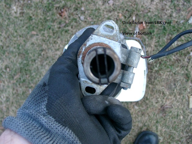 I was not able to get a good look down into the hole into which this slides to get a good look at what's in there. I am presuming it's a spindle with two straight cuts across it (black & grey in this drawing) over which the shaft base from the distributor slips (shown in blue). Would this be correct?  Brian | ||
David Lacey Experienced User Username: dlacey Post Number: 39 Registered: 11-2010 |
Hi Brian, The dizzy drive looks like a flat bladed screwdriver tip pointing upwards, about 1/2 inch wide. As you say the drive fits into that slot in the dizzy base.. | ||
Brian Vogel Grand Master Username: guyslp Post Number: 1210 Registered: 6-2009 |
David, Thanks. I wonder why they went to all the trouble they did as far as those two little metal pieces being inserted into the base and then bound in place. It would seem much easier to just cut a channel in the center, much like a slotted screw, and be done with it. I hadn't even thought of that simple arrangement due to the way the base of the distributor is designed. Brian | ||
Geoff Wootton Grand Master Username: dounraey Post Number: 640 Registered: 5-2012 |
Hi Brian Note that it is possible to re-insert the distributor 180 degrees out. This is why it is always important to note the position of the rotor arm before removing the distributor and to not rotate the engine with it removed. Geoff | ||
Brian Vogel Grand Master Username: guyslp Post Number: 1212 Registered: 6-2009 |
Geoff, We were typing "the same thought" on two different threads. I find myself in the "potentially 180 degrees out" situation on LRK37110. I'd imagine if this is the case the engine either will not start or will run *horribly* for a brief period. At least all it involves (I hope) would be taking the distributor off again and rotating the arm 180 degrees and reinstalling it. Brian | ||
Geoff Wootton Grand Master Username: dounraey Post Number: 641 Registered: 5-2012 |
Hi Brian When the dizzy is put in 180 degrees out the engine will not start at all (how do I know this). You are right, all that is required is to pull the distributor up in the housing until the slot is disengaged and rotate it 180 degrees. BTW - I have just checked some photos of my distributor and my above statement is wrong - many apologies. The slot is the same as on the SY2. I will edit out that statement now, if I am still in the time frame. Geoff | ||
Bob Reynolds Prolific User Username: bobreynolds Post Number: 233 Registered: 8-2012 |
On some Lucas distributors the slot is not exactly down the centre, but slightly off-centre. This makes it impossible to put it in the wrong way round. I've never had occasion to remove the RR distributor, but from the above comments, it looks as though the RR distributor is not made like this. | ||
Brian Vogel Grand Master Username: guyslp Post Number: 1214 Registered: 6-2009 |
Bob, You can tell from my first photograph, and this one of the base of the distributor that came out of SRH33576 (pre-cleanup) that the "slot" created by those two thin metal pieces is perfectly centered. 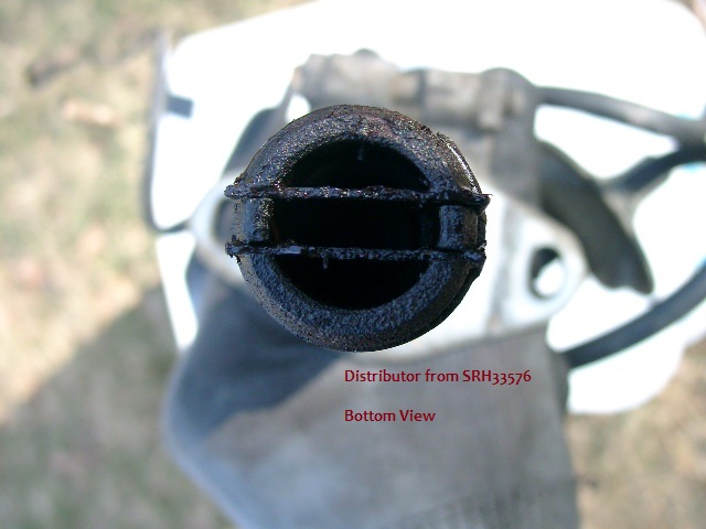 I'd still love to know what drove this design, with the two very small metal plates that serve to create the channel and the clip that is used to hold them in place, as opposed to just cutting a channel through a solid piece of bar stock. It seems like a whole lot of effort for no apparent reason. Brian | ||
Kelly Opfar Experienced User Username: kelly_opfar Post Number: 31 Registered: 7-2004 |
Brian, the screwdriver-esque blade actually has a slight curve to it. It is very tight when it slips into the spring blades in the bottom of the distributor. The curve of the deformed spring blades then matches the curve of the drive blade. I assume this is done so the dizzy drive will have a very tight fit without super-precision machining techniques. 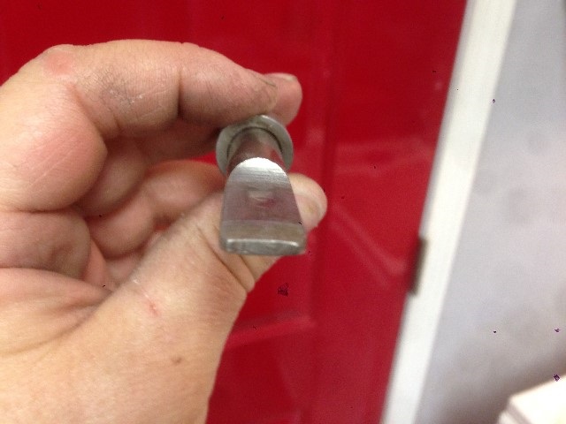 | ||
Kelly Opfar Experienced User Username: kelly_opfar Post Number: 32 Registered: 7-2004 |
 | ||
Brian Vogel Grand Master Username: guyslp Post Number: 1215 Registered: 6-2009 |
Kelly, Thanks. At least this makes more sense knowing this. I'd still think that a "very tight" fit would likely be unnecessary since the thing is being constantly driven when the engine is running and with each end of a straight blade pushing on the opposing side of a slot it would be effectively held in place. The pictures that are popping up on recent threads really are worth a thousand words!! Brian P.S. Is that a replacement "clamping bracket"/mounting bracket on your overhauled distributor? The finish seems to be almost impossible to get otherwise. It also has a design that looks more robust than what's on mine. | ||
Kelly Opfar Experienced User Username: kelly_opfar Post Number: 33 Registered: 7-2004 |
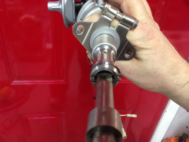
The clamping bracket is the stock unit although I did weld the square nut on so it wouldn't get dropped. It was sand-blasted then glass bead-blasted then electroless nickel plated. The bead blasting gives it a nice satiny sheen that looks great when plated. The lower "blade" receiver portion of the distributor was manufactured new out of a high-strength stainless alloy. | ||
Richard Treacy Grand Master Username: richard_treacy Post Number: 3182 Registered: 4-2003 |
All of the above is the same as on a Chevrolet. Or Holden, Vauxhall, Dodge, Mustang, BMW, Hispanio-Suiza or Morris. Trabants may be different as they are 2-strokes. | ||
Paul Yorke Grand Master Username: paul_yorke Post Number: 1365 Registered: 6-2006 |
The spindle accelerates and decelerates very slightly as the points heel runs over the cam, any play in a slot at the driven end would chatter and wear I guess. The metal clips are spring steel so hard as well. ??? | ||
David Lacey Experienced User Username: dlacey Post Number: 40 Registered: 11-2010 |
Agree that the design is optimised to limit backlash, which is the weakest link in a cam-driven dizzy. The drive finger is wedge shaped, the receptacle on the dizzy is spring steel, it's designed to fit snug with no rattle. | ||
Brian Vogel Grand Master Username: guyslp Post Number: 1513 Registered: 6-2009 |
Today I took the Mallory distributor and the old Lucas distributor to the machine shop to have the drive interface between the drive finger and the distributor shaft itself transplanted from one to the other. The machinist asked me a question I cannot answer: Is the pin that holds the interface bit to the distributor shaft a taper pin or not? I would think not, just looking at each end, but the taper could be very subtle. I'd like to be able to give him a definitive answer before the work begins. Also, how easy or difficult is it to transfer the distributor clamping bracket from old to new. It looks as though it should open wide enough to just drop it off. Brian | ||
Robert Noel Reddington Prolific User Username: bob_uk Post Number: 291 Registered: 5-2015 |
I think maybe the drive design is designed to shear should the dizzy seize up. Plus as the dizzy and shaft turn the line up of the dizzy and shaft won't be dead on. This design allows flexibility at the coupling. The slot in a shaft is common on other cars such as Mini.The slot is clearance fit to allow for misalignments at 90 degress angle to the slot and blade. A taper pin of that length would be obvious due to different diameters. | ||
Kelly Opfar Experienced User Username: kelly_opfar Post Number: 38 Registered: 7-2004 |
I wouldn't hesitate to use a roll pin. Taper pins complicate things unnecessarily. They require taper drill/endmills and they come loose at the most inopportune time (which is anytime). The clamping bracket should slide right off. You might need a screwdriver as a persuader. | ||
Brian Vogel Grand Master Username: guyslp Post Number: 1514 Registered: 6-2009 |
Bob & Kelly, Thanks for the input. Please don't take the following as lacking in that appreciation, but I'm wondering if anyone, in this case, knows absolutely whether a taper pin was used or not? In the final analysis, I'm going to let Tim do whatever he deems best. He was wondering if it was a taper pin more related to the removal of the original. I figure someone who's reading these forums has probably done a "drive interface swap" at one point or another and was wondering what was found at the time. I will report back as to what Tim actually does. The one thing I really wanted him to do, and which he can and will do, is to maintain the relationship between the drive interface, the pointing direction of the rotor arm and corresponding pickup placement. With a little planning one should be able to avoid turning the engine at all. If I maintain the relationship between the interface and the rotor arm/pickup, and also the distributor itself and the clamping bracket I should be ready to do "fine tuning" with regard to timing rather than it becoming a major production number. Kelly, thanks much for the input on the clamping bracket. From everything I can see the situation you describe should be the case, but I always fear that I'm somehow overlooking something. Better to ask those who've "been there, done that" than to assume my observations are correct. Brian | ||
Kelly Opfar Experienced User Username: kelly_opfar Post Number: 39 Registered: 7-2004 |
Brian, I had to check my old pics but it is clear now that my drive interface was originally attached with a taper pin p/n X4802/R. Since I made my new drive interface from stainless (see above pic), I attached it with a spring roll pin. | ||
Brian Vogel Grand Master Username: guyslp Post Number: 1515 Registered: 6-2009 |
Kelly, Thanks very much. I've shared this info with the machinist. Brian | ||
Robert Noel Reddington Prolific User Username: bob_uk Post Number: 292 Registered: 5-2015 |
A roll pin is normal practice on dizzys. A taper pin can be secured with loctite brg fit engineering glue. Roll pin better. |