| Author | Message | ||
Dave Puttock Experienced User Username: ariel Post Number: 41 Registered: 5-2010 |
When I stripped my front doors to replace the window runners I found that the support for the fixed quarter light had rusted to almost nothing. So after drifting out the remains of the three fixing screws I dug out all the remains down to the bottom rubber. 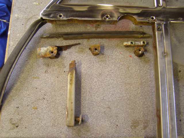 At the end adjacent to the window runner I found a small cast aluminium block but I cant fathom out its purpose. 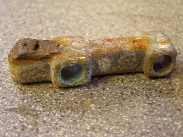 It has 2 unthreaded holes which match up with 2 holes on the inside of the frame and the remains of a screw I think in the vertical axis. The rubber seems to have a hole which would line up with the screw but I can't believe that the screw could bear on the edge of the glass otherwise it would act as a stress raiser and break the glass. 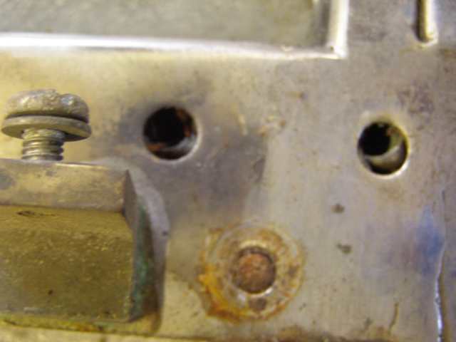 But similarly even if it were to support the glass it doesn't apper to be fixed in any way as there are no screws in the holes. I have looked at other doors in RR specialist breakers but they all seem to be in the same condition so I take it that this is a common condition. I don't suppose the parts are available so I am prepared to have a go at making replacements but I have no idea what the original looked like other than being a channel with three bosses and a leg at the front. What should it look like at the end where the aluminium block is. Anyone got one or a picture of one? | ||
Chris Browne Prolific User Username: chrisb Post Number: 179 Registered: 2-2010 |
Hello Dave, I have looked on the parts list available on this site and I think the part is called a tapping block. If this is, indeed, what it is, its purpose was to support the base of the drivers door mirror. Two screws passed through it then through the bottom of the window frame and then into the door mirror stem. At least I think that is what it is! Kind regards, Chris | ||
Dave Puttock Experienced User Username: ariel Post Number: 42 Registered: 5-2010 |
Ah that would make sense, the holes are there on the inside but you only drill through the out side if you want to fit a mirror there. Still I would like to know how the channel section is constructed around it. | ||
gordon le feuvre Frequent User Username: triumph Post Number: 61 Registered: 7-2012 |
It was there to support frame if mirror was fitted in service, it was a option. If the block was not there the frame would have collapsed when mirror arm was tightened. Out of interest(or not), I did the PDI/check over on the Corniche fixedhead that I now own. The owner would not pay cost of factory mirror, but instructed me to drill door and fit Unipart one! It is still on car. CRH15049 | ||
Bob UK Unregistered guest Posted From: 94.197.122.91 |
I remember the unipart mirror. I would have thought without the tapping block (how quaint it's actually a door mirror support piece) that the door skin would distort because the mirror can't match the skin curve exactly. I would design a way to repair it without worrying too much about originality as long as the visible stuff is the same and the repair is a good quality nice looking sensible bodge, that looks factory made. Note, when working with polished stuff, gaffer tape will protect it from the inevitable knocks while repairing it. When gaffer tape is removed it leaves glue behind, remove with white spirit. If it's chrome then wax polish immediately to reseal the pores. The tapping block is easy' to make. A nice lump of brass or aluminum, then start filing. That will keep you happy for a couple of hours. Best way to mark off hole distances is to centre punch the first hole position. Then using dividers scribe the distance. To set dividers use a steel rule not a tape measure. To check the dividers use the mirror foot. Place very tip against side of hole and should touch the other holes side. Then by eye judge the centres. This is accurate to 0.005" done with care. I Have a 12" rule with cut graduations, the dividers fit in the lines. If a line on a rule is 5 thou thick then the edge must be 2.5 thou. Using a mag glass and good lighting one can be surprisingly close measuring with a rule. Centre punches for dividers are best at 60deg included angle. This tends to be to sharp for drilling so it's best to use a centre drill first. This will work as a pilot drill. The centre drill doesn't need to go all the way through. It will give an excellent start to the tapping size drill thus giving a well centre tidy hole. Tape measures are for builders. Time for tea. (Message approved by david_gore) | ||
Dave Puttock Experienced User Username: ariel Post Number: 43 Registered: 5-2010 |
Now that you can buy a digital vernier for less than 10 GBP in Aldi. I find it easier to use the vernier as if it were dividers and scribe a fine line with the points | ||
Dave Puttock Experienced User Username: ariel Post Number: 44 Registered: 5-2010 |
Ok, so this is what I've made. Admittedly it took nearly 10 hours to fabricate a pair of them, but shotblast and paint and we should be good for another 40 years. 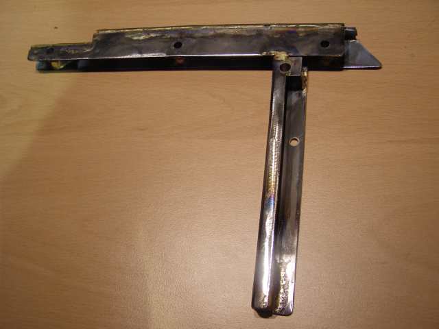 | ||
richard george yeaman Prolific User Username: richyrich Post Number: 248 Registered: 4-2012 |
Hi Dave good job!!!its all about the satisfaction of doing it yourself. Richard. | ||
Geoff Wootton Grand Master Username: dounraey Post Number: 605 Registered: 5-2012 |
I agree - nice job. | ||
Bob UK Unregistered guest Posted From: 94.197.122.91 |
A nice sensible neat bodge. A spot of paint and it will look even better. I brought a digital calipers for �10 in a plastic case. I checked them and they are within 0.5 thou or 100th of a mm. So that's good enough for most stuff. A 0 to 25mm micrometer is a very useful addition. These are about �10 second hand. Also a new 1/4 diameter ball bearing with a little tube to hold it on the micrometer anvil for inside tubes and things. Using a steel rule measure something then measure with digital calipers and with practice one can get quite close. Second tool shops are a God send. My local rusty tool cave has a huge inventory. Incidently although it's tempting to use the inside jaws of the caliper as a Scriber when marking hole pitch, be aware that it gradually degrades the accuracy of the points. I use a permanent marker then scibe a line down the middle. Which highlights the line. On a lathe to find position I start the lathe, mark with permanent marker then touch with tool to just remove the ink, then zero dials. Now from that datum I can wind on a cut if it needs 50 thou off wind from zero 40 thou. Take a cut. Then measure then correct calculations and wind on another amount to fit the new calculation. Usually it's 10 thou but sometimes due to a small bit of wear one has wind 9 thou. On milling machines. I stick a fag paper on the workpiece when the cutter hits the fag paper it's a 1 thou away and just a nudge on the dial and it's bang on. Any closer and I put a gnats cock on it.  (Message approved by david_gore) | ||
Geoff Wootton Grand Master Username: dounraey Post Number: 607 Registered: 5-2012 |
Bob Hardly a bodge. It's a nice piece of fabrication that will be indistinguishable from the original once fitted and painted. Geoff | ||
Patrick Lockyer. Grand Master Username: pat_lockyer Post Number: 926 Registered: 9-2004 |
Bob a bodge never, with all yours skills and methods on jobs that seem endless maybe you could submit some pics of your finished work so we can see the end picture. Ie a pic of the engine bay and your painted car would be of help. | ||
David Gore Moderator Username: david_gore Post Number: 1516 Registered: 4-2003 |
Pat, Bob is a Guest contributor and not a Member so he is unable to include images or attachments in his posts. | ||
Patrick Lockyer. Grand Master Username: pat_lockyer Post Number: 927 Registered: 9-2004 |
David, maybe Bob could submit some pictures of his Shadow to you so you could indeed post them. Seem to remember some Range Rover pics on here from himself! Pictures can generate much intrest and discussion, most intrested in the engine bay with LPG setup. | ||
Geoff Wootton Grand Master Username: dounraey Post Number: 609 Registered: 5-2012 |
I agree. The LPG setup would be interesting, particularly for EU members of the forum. | ||
Bob UK Unregistered guest Posted From: 94.197.122.87 |
The word bodge doesnt mean botch. Bodge means repairing to a proper standard but not as original. This is what I call a sensibly engineered quality bodge. The aim is in this case is fix the frame so that from the outside it looks perfectly standard and is robust. The inside bits are neat robust and will last many years. Especially if painted and assembled with grease smeared on as its assembled, especially where surfaces are bolted together. I was not saying that the job is bad, I actually saying the opposite and once painted it will look EVEN better. I do apologize if my engineering English is misunderstood. So now I shall refrain from using the phrase "sensible engineering bodge." My view is that I have never seen a restored car that is exactly as it was when it was new. It's impossible. Typically when car bodies are restored panels are cut and shut with new metal. This leaves a weld seam that wasn't there when new. This is the same as the job above. Absolutely nothing wrong in that, because if the panels weren't cut and shut then the restoration wouldn't be possible. I have a diploma in Historic Vehicle Restoration with distinction. It starts at 1890 with the first cars. My speciality is knowing how to make stuff. Once one knows how 90% of the problems are solved. The skills I have are not difficult to learn it's just patience. My aim is inform of easy ways that work. I learnt these from other people. I was shown dividers when I was an apprentice and it takes 15secs for the penny to drop and to realise how useful they are. Regards Bob. (Message approved by david_gore) | ||
Patrick Lockyer. Grand Master Username: pat_lockyer Post Number: 929 Registered: 9-2004 |
"Bodge means repairing to a proper standard but not as original." Not in my book! ie to patch to mend in a clumsy fashion; to construct clumsily: bodge - boger. And Dave made two in two days, yes that in my book is class workmanship. Now come on Bob send some pictures of your Shadow engine bay for David to do a posting of them. | ||
Bob UK Unregistered guest Posted From: 94.197.122.81 |
I will see if this mobile will take photos and attach them. I shall send a test first. If it works I may pop the carby toots off to show the gas nozzles. My u pipes need painting anyway. I shall try tomorrow. I am sorry about the misunderstanding over the word bodge. (Message approved by david_gore) | ||
David Gore Moderator Username: david_gore Post Number: 1518 Registered: 4-2003 |
Bob, You will not be able to post pictures as a Guest contributor so do not waste your time trying the impossible. I can help you post pictures if you wish - just email them to me as attachments to the email plus a description to go with each photo. I will do any editing necessary for them to fit on the page and post them on the Forum with acknowledgement to you. If possible, send them as large files greater than 2Mb as these give best results when viewed on the Forum. | ||
Bob UK Unregistered guest Posted From: 94.197.122.85 |
Dave, I tried first attempt and the phone didn't have enough ram. Then I trashed cleaned the phone. second attempt I got not acceptable because jpg larger than 1 kb. So I gave up. I shall send them as you suggested. Today I am servicing a 500 watt floodlight ready for photos, and I am making a bracket to fit a tripod for the light. (Message approved by david_gore) |