| Author | Message | ||
Brian Vogel Grand Master Username: guyslp Post Number: 1002 Registered: 6-2009 |
Hello All, Recently, a correspondent sent me the following two pictures of the regulator valve disc that was (and is) in his ACV: 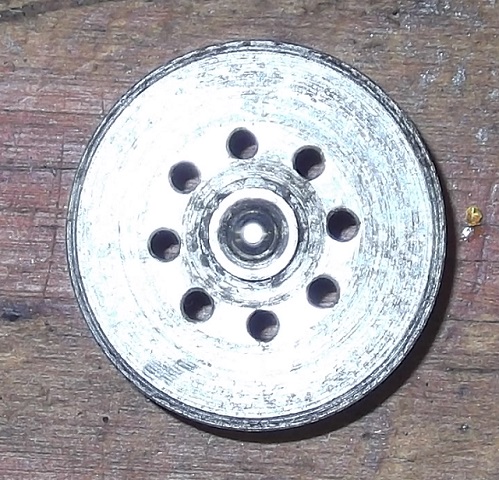 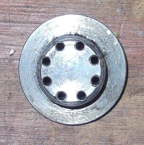 All of these that I've seen, whether coming out of an ACV or in a rebuild kit, have no holes. The ACV diagram from the SY1 Workshop manual appears to show these holes in the disc: 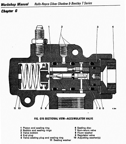 while the corresponding diagram in the SY2 Workshop Manual does not. I'm just wondering if anyone: 1. Knows what the original thought behind the holes was. 2. Knows when they were deleted. 3. Has ever encountered one of these beasts. 4. Knows if there exists any reason to change them out for the later style. Brian | ||
Bob uk Unregistered guest Posted From: 94.197.122.77 |
I have only seen pictures so I am guessing. The holes allow dot to move from the spring chamber to the non return valve and behind the piston which then pushes against the spring to dump pressure back to tank. Because the dot can't go back through the non return valve it holds pressure against the back of the piston holding the relief open. Until the rest of system demands pressure, such as a brake application. Then when the pressure drops behind the piston the piston is pushed to the right (in the picture from the manual) which closes the relief and the pump starts pumping, and so on. Like I said I have never probed a RR/ Citroen acc. And finding a spring top hat(part 9) without holes is a puzzle because how does the dot get to the non return valve? (Message approved by david_gore) | ||
Brian Vogel Grand Master Username: guyslp Post Number: 1003 Registered: 6-2009 |
Bob, I could go into nauseating detail on the ACV just having spent the better part of a week going over the workings of same over and over in my mind and on paper. However, the regulator valve disc has always been significantly smaller in diameter than the bore in which it sits on the end of the big spring (and this is reflected in the diagram), so fluid can easily flow around its circumference, and that's precisely what it does in every other instance I know of than the ACV whose parts are pictured. There have got to be others with the regulator valve disc with holes, but I'm really curious at how early on those holes were deleted from the design. It was definitely well before the advent of the SY2 series cars. The "big hole" at the end of the bobbin is the tube that leads to the non-return valve, and once the regulator valve closes there's still a huge offset between the face of the regulator valve disc and that hole. Fluid just flows around the disc and into that hole until the pressure is sufficiently high to push the non-return valve open and charging then begins. Brian, who is amazed at the logical simplicity of the accumulator control valve | ||
Bob uk Unregistered guest Posted From: 94.197.122.84 |
The workshop manual is very much intended for mechanics who have been on a factory course to learn the product knowledge. The rest of use have to work it out for ourselves which I suspect is probably better because to work it out you have to think about it and fit the information from the manual to one's visualization any thing that doesn't fit means one's visualization is wrong. The acv is a simple crude but effective demand valve that is nicely made. The piston is a spool valve that when the relief is shut connects the pump to the sphere and when the piston opens the relief the pump is then connected to the dump line and disconnected from the sphere whose pressure reserve is held in check by the non return valve. The spring on the return valve only has to shut the valve and the relief pressure is controlled by the big spring. Note RR didn't put a screw adjuster that could be adjusted by taking a plug out of the spring end. All that is required for overhaul is 3 O rings and 30 minutes. The way I look at the system is that the pump tank and acv are the power station and the brake valves and ride height are substations and the calipers and suspension rams are the consumers who have to send back the empties ( dump or return pressure) or the power station will run out of bottles to send the power in. The RR system is simple in the world of hydraulics. The design is so simple that it is brilliant because RR have done the job with the minimum of parts. The restrictors fitted either side of the solenoid valve also serve as tee pieces for the supply to the ride valves and the other restrictor is also a tee piece for the returns. Less parts less pipes less joints to leak. Check out moog hydraulic cnc systems and ones brain starts dribbling out of one's ears. Where does the dotted channel (hidden detail) come from and go to ?. (Message approved by david_gore) | ||
Bob uk Unregistered guest Posted From: 94.197.122.91 |
I am not sure about this because this is outside of my hydraulics knowledge. When fluids are under pressure more effort is required to move through it. The top hat has holes so it can move through the pressurised liquid easier. Or some one was going through the design of the acv and realised the holes were an unnecessary extra matching operation because the holes served no purpose. Or my first guess is right and the engineers found the damping effect of no holes worked better. Like a spoon in treacle. I was silly sausage in not noticing the enormous gap behind the top hat and not seeing all the seals. (Message approved by david_gore) | ||
Chris Miller Prolific User Username: cjm51213 Post Number: 225 Registered: 5-2013 |
Hi Bob, > Where does the dotted channel (hidden detail) > come from and go to ?. If you mean this channel: 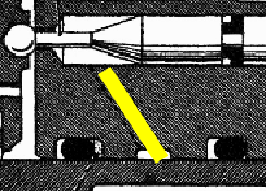 then that is the "dump" path. High pressure fluid from the pump enters the chamber with the spring and has only one path out and that is through the check valve ("non-return valve"), until the piston emerges at which time the regulation valve permits fluid to enter the piston chamber through the pointy end where it returns to the brake fluid reservoir. You can see that the "hidden channel" communicates with the ring that is connected to the return fitting on top. Chris. | ||
Chris Miller Prolific User Username: cjm51213 Post Number: 226 Registered: 5-2013 |
> When fluids are under pressure more effort > is required to move through it. This is not true. Pressure has no effect on viscosity. Fish can still swim at the bottom of the ocean. | ||
Brian Vogel Grand Master Username: guyslp Post Number: 1006 Registered: 6-2009 |
Bob, When I have things apart I'm very thorough about photo documentation so that I don't have rely on memory when questions come up later. You've asked a good one on that "dotted channel" in the ACV diagram and it's one I can answer in two annotated photos and a hand colored modified ACV diagram: 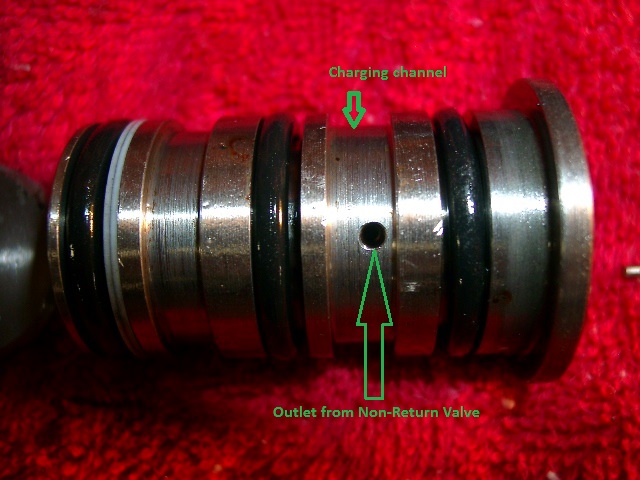 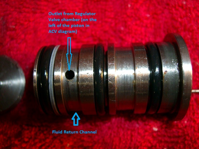 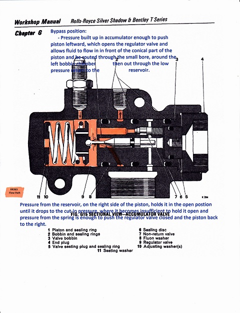 When the ACV is in return/bypass mode, the regulator valve is pushed open and the fluid flows into the chamber on the left side of the piston (using the diagram for orientation), through that the outlet for that chamber and into the return channel that surrounds the bobbin and lines up with the low pressure return line on the top of the ACV valve body, then out of the ACV back to the reservoir. Brian P.S. to Chris: You beat me to it. I was editing the actual bobbin photos to add annotations while composing. The colored diagram is one of the results of days of thought exercises. | ||
Chris Miller Prolific User Username: cjm51213 Post Number: 227 Registered: 5-2013 |
Hi Brian, > P.S. to Chris: You beat me to it... High praise, indeed. Chris. | ||
Brian Vogel Grand Master Username: guyslp Post Number: 1010 Registered: 6-2009 |
P.P.S.: I want to correct an error the second comment in blue in the modified ACV diagram that I hadn't noticed until just now. It should start with, "Pressure from the accumulator," not reservoir. Brian | ||
Bob uk Unregistered guest Posted From: 94.197.122.88 |
I don't understand the section drawing because I visualize the hidden detail as not hidden. Now I know that the hidden detail connects the dump line to the chamber to the right of the ball around the piston ball lift pin. The names RR have called the bits confuses the way it works. The regulator valve is a spring and top hat. The ball is the relief valve. The ball should be burnished to the bobbin not the spring and top hat. Very confusing. Also this valve is not a regulator it is a relief valve. The whole valve is a combined pump relief and demand valve. One can't really blame RR because it's a repair manual not a how it works manual. A word of warning this valve ( the whole value) does not have a fail safe relief set at a say 2600psi. This means that if the piston jams in the shut position say due to the piston seal shredding or the non return valve not opening because the small spring is coil bound, then the pump push rod will snap. So be care ful with the piston seal and that tiny insignificance spring. I would assemble the non return valve in the bobbin and check that it lifts by pushing it from the left side of the bobbin before fitting. (Message approved by david_gore) |