| Author | Message | ||
Chris Miller Prolific User Username: cjm51213 Post Number: 160 Registered: 5-2013 |
Hi Folks, There was discussion about the pressure necessary to open the accumulator pressure switch and extinguish the red warning light on the dash. Bob (UK) suggested that they open at 1,100-ish PSI, and my experience is that mine open at nearly 0 PSI. So, I put them on my pump and I measured them. The pump is not pictured, nor is the battery, but imagine a source of hydraulic pressure and 12 volts from the brown lead to the switch body. In your mind you should see the light is on. As I apply pressure with the pump, the light will go off and I can see the pressure necessary to accomplish this on the gauge. One of my switches opens at effectively 0 and the other at about 200 PSI. 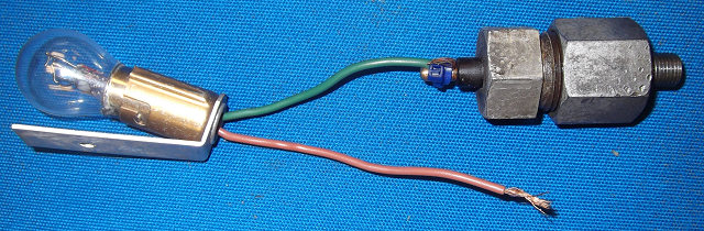 So my switches open at far too low a pressure, in my view, because they are not warning me of an incipient failure, they are alerting me to fait accompli -- "Sorry, Chris! You're screwed! Better luck next time!" I want to discover that I have a problem before I'm in trouble. I'd really like them to open at about 1,800 PSI, meaning I still have (33.5 cu.in - 18.6 cu.in.) ~ 15 cu.in. of fluid left, which is almost half. This is a provisional goal, because it might turn out that the accumulator reaches 1,800 PSI too frequently during normal operation and so the warning becomes "crying wolf" and ignored. So, I may need to adjust that value, but for now that is where I think I want to be. So, how does this damn thing work? I have tried to open these guys several times before and I gave up because the cap was torqued on so tight that I feared damage to the switch, which was imprudent under the goal of opening it to see how it worked. But now that I have measured them, it is clear that I need to open them up. I was persistent and successful. Apparently, a previous owner suffered brake fluid leaks, and torqued the snot out of them to stop the leak, which worked, but the real solution is to replace the missing o-ring at the base. 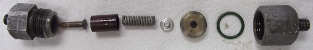
There are several challenges this thing must meet. First, it is on a pressurized hydraulic system, so it must not leak fluid. Second it is electrical. The plug is held rigidly against the steel rim of the switch body (male) which transfers compressive force to the o-ring at the base of the switch body (female). The bottom of the switch body (female), the o-ring and the rubber face of the brass plug form the brake fluid containment volume. Notice the fluid under pressure in the volume will deform the flexible rubber component of the plug. Under electrically "closed" operation there is electrical continuity from brass external terminal, through the spring to the aluminum spring cap, to the brass body of the plug, which is in contact with the lip of the switch body (male) completing the circuit from the external brass terminal to the switch body. As the brake fluid is forced in to the containment volume, under pressure, the rubber component of the brass plug deforms which has the effect of emerging the small, stubby post on the reverse side. The post lifts the aluminum spring cap and breaks continuity. If the spring is stronger, it requires greater pressure to open the switch, and conversely, if the spring is weaker, it requires less pressure. I can't change the force constant of the spring, but I can compress it with a shim, effectively making it "stronger". My first question, how sensitive it this operation to the sealing torque between the two parts of the switch body? The answer is, "Not very sensitive", and it makes sense The spring is contained by the rather rigid constraints of the switch body (male) and the top of the plug and these don't change under varying values of closing torque. So, that is good news because it eliminates a variable. So I tried some very small washers I had. I got these results:
Apparently, the "open threshold" is very sensitive to the properties of the spring! Tonight, my plan is to reduce the granularity of the spring length from steps of "washer thickness" to "foil thickness", because a washer is apparently far too thick. I will have more to report, as I learn more. For your consideration, Chris. | ||
Chris Miller Prolific User Username: cjm51213 Post Number: 163 Registered: 5-2013 |
Hi Folks, I spent a few hours trying to determine the calibration constant of pressure/disk of foil, and I had very difficult and frustrating time. I got wildly inconsistent measurements and other unexplained behavior. After many, many experiments, I began to realize that my understanding of the containment chamber was completely wrong.
Well, it turns out that the o-ring that I improvised as component 7 above is completely wrong. I'm sorry that nobody else caught that, engineering is a team sport, but I'm glad that I did. I began to suspect this in the face of wildly inconsistent readings and that I clearly wasn't getting brake fluid containment, because, although I wasn't seeing external leaks, I was seeing brake fluid in the electrical chamber of the switch body. As I thought about it, it became clear that the brake fluid was escaping between the brass skeleton of the cap and the rubber diaphragm through the hole for the "plunger" which lifts the aluminum spring cap. The witness marks on the o-ring were also an indication that, at a minimum, the o-ring was not fitted properly, and in fact was not only unnecessary, but an interference. I examined the earlier pressure switch design from the '66 and I could see by the differences in the bottom of the switch body (female) what the design was and how it was supposed to work. The recess that I thought was a clue to a missing o-ring is in fact a recess for the lip of the brass portion of the cap so the shoulder at the base of the switch body (female) can compress the edges of the rubber diaphragm in the cap which forms the containment chamber between the bottom of the switch body (female) and the rubber diaphragm, no o-ring required. In fact the o-ring that I improvised interferes with this design. As you look into the switch body (female), you will see a "gutter" at the base forming a shoulder, which I interpreted as an o-ring cavity, but it is a recess to accommodate the lip of the brass skeleton of the "plug". The shoulder seals against the rubber diaphragm interior, and this becomes the containment region. So, now I have a new understanding of the design and operation of this switch, I will correct my misunderstanding and assemble it correctly and try again to calibrate it with foil shims on the spring. For your consideration, Chris. | ||
Chris Miller Prolific User Username: cjm51213 Post Number: 166 Registered: 5-2013 |
Hi Folks, This is an incredibly robust device. It seems immune to tampering -- read that "calibration". I keep expecting to see some sort of linear response, but I see no effect until I see "disabled"... I have a plan to measure the pressure response of the plunger, which will eliminate all the theoretical failure modes that may be preventing my "tampering", like for example the aluminum cap on the spring "tipping" and not breaking contact if the spring force exceeds some threshold value. It seems to me that changing the length of the spring by the thickness of a piece of foil (.001") should give me a linear response curve, because I can't imagine that a mechanical switch has tolerances anywhere nearly that tight, but so far, I get a set point of 200 PSI, or malfunction. Both of my switches respond at very low pressures, and neither exhibits any defect that would be changed by "renewing" anything; both respond identically within the intuitive tolerances of the device, which raises the question, where does the 1,200 PSI number that has been reported originate? I would be quit happy if my switches had this set point... Is this 1,200 PSI set point number in the manual or is it simply echos of unsubstantiated (and incorrect) reports of long ago? Bob (UK), you reported a number in this range. Where'd you get your number? Thanks for you help, Chris. | ||
Brian Vogel Grand Master Username: guyslp Post Number: 924 Registered: 6-2009 |
Chris, I am going to beg you, again, to please consult the Workshop Manuals for both the SY1 and SY2 series cars when you're looking for the kind of data you're requesting here. It's often in one or the other, sometimes both. In this case it isn't in the Hydraulic Systems chapter for the SY1 series cars but is in Chapter G14 - Pressure Switches of the SY2 workshop manual. People will have different, but still accurate, recollections depending on the cars they've worked on, where they've worked on them, and what their original delivery dates and markets were. As per usual, things were different depending upon market of delivery and time of production. I was actually shocked to see that the illumination threshold for what I assume were the home market cars was 250 PSI. The details are on the first page of the chapter. If your car is SRHXXXXX then you likely have one of the switches with a *really* low threshold (and I'd think that after the decades +/- 50 PSI is possibly due to wear). You will want to fit one of the later switches which should still be available in the USA through Bentley Zionsville AKA Alber's or Bentley Long Island or Post Oak Motors in Houston. You could also seek out a used switch from a car delivered to the US market, but then you'd need to overhaul that and the cost would probably end up being as much as a new switch (though I haven't priced the switch as a whole, I have purchased a rebuild kit several years ago). It may be possible to rebuild yours with a kit that would increase the pressure and the folks at Bentley Zionsville could definitely tell you whether that is possible or not. The only two routes I would consider are brand new switches or rebuild with kits that would increase the pressure where the light extinguishes to 1200 PSI. Brian | ||
Chris Miller Prolific User Username: cjm51213 Post Number: 167 Registered: 5-2013 |
Hi Brian, > As per usual, things were different depending upon market > of delivery and time of production. I was actually shocked > to see that the illumination threshold for what I assume > were the home market cars was 250 PSI. The details are on > the first page of the chapter. If your car is SRHXXXXX then > you likely have one of the switches with a *really* low > threshold (and I'd think that after the decades +/- 50 PSI > is possibly due to wear). Smokin'! Yes, the '72 is SRH13161. And the +/- 50 is much more likely the granularity of my gauge, which is 0-10,000 PSI, so "50" is 3.5 significant digits, and I think I'm lucky to get 3. My question was not intended to impugn the integrity of any information offered freely, but to help me explain my incongruous measurements. We now see that my measurements are correct, and despite my ardent desire to see 1,200 PSI, and the frequent suggestion that I should see 1,200 PSI, I didn't. This also tells me that my switches are functioning completely normally and correctly. It also tells me that I want to do something about this, and it appears that I can't calibrate these with any modification I have designed yet. I may still succeed, but I'm much less interested in trying, now. I don't typically look in the SY2 manual because I only have SY1 projects... Thanks for the help, Chris. | ||
Brian Vogel Grand Master Username: guyslp Post Number: 925 Registered: 6-2009 |
Chris, I didn't believe that you were trying to impugn anyone's integrity. I just wanted you to understand that people can and will sometimes tell you different things and that those different things are very often true depending on when the car was made and its original delivery market. Even though you only have SY1 projects (as I only have SY2) you'll often find it useful to refer to the SY2 manual to see if data that was not in the SY1 manual is now included. The interesting thing, as I long ago learned, is that this goes both ways. Some things were deleted from the SY2 documentation that were originally present in the SY1. In fact, I've gone back to documentation from the Silver Wraith era cars when I was rebuilding my dual SU fuel pump. The documentation was much more thorough in those, at least as far as exploded views go, and the changes in the pump were minimal over the decades. Brian | ||
Chris Miller Prolific User Username: cjm51213 Post Number: 168 Registered: 5-2013 |
Hi Brian, > ... people can and will sometimes tell you different things > and that those different things are very often true depending > on when the car was made and its original delivery market. Yes. You are saying that "truth", is related to context, as is well expressed by the story of the blind men and the elephant. I was seeking context. You provided it. Thanks for the help, Chris. | ||
Bob uk Unregistered guest Posted From: 94.197.122.93 |
Chris me lad. Do do as Brian says if you are going spend hours setting them use the right settings. Mine are 1550 and 1490 psi. 1500 psi will lock wheels. More than once from 150 mph. You have yet to drive the beast with 100% brakes The brakes are frigging awesome. Top speed 118 mph UK spec car. (Message approved by david_gore) | ||
Chris Miller Prolific User Username: cjm51213 Post Number: 169 Registered: 5-2013 |
Hi Folks, Success! I've re-calibrated my pressure switches to engage the warning light at 1,600 PSI. They extinguish the light at a point that falls in a wider distribution, but always below 2,000 PSI, so that variable is not important. They engage the light at a pretty consistent point, which is the important behavior. I want to know that when the light goes on, it means a known pressure, but I don't really care when the light goes off, so long as it does. This was quite a frustrating project because I couldn't figure out why I was getting such variable and non-linear results. I have discovered that I need to be exceptionally disciplined and use an absolutely reproducible procedure to assemble the switches to get reproducible results. I identified a few points of variability in the re-assembly, determined steps to remove the variability, and Voila! no more variability, and I was able to find an acceptable combination of shims to calibrate my pressure switch to the set point I wanted. Sunday, I can re-assemble my spheres and ACVs, bench test and measure the assemblies to verify no leaks and correct by-pass operation of the ACV. I may re-install immediately, or I may let them sit on the bench and age and stew, before I re-install them. Soon, I can resume as my daily driver. I'd like to take a moment to remind David Gore not to drive in the U.S., especially around Sacramento, as I will probably be driving there. (-: I have already ordered two electronic pressure transducers and designed the circuit, called a "voltage comparator", to replace these mechanical switches. The electronic "sender" will give me a voltage which represents the current pressure reading as a proportion of the range of the device. This is called "ratiometric". The voltage comparator will decide if that voltage is below an arbitrary value that I set, and if so, will engage the red dashboard warning light. But wait, there's more! Since I have an analogue of the pressure in that ratiometric voltage, I can put a gauge on it and read the current pressure. For now, that will be a pair of mechanical gauges, and I have to find a place to put them. I think I want to overload existing gauges, the way the test button overloads the fuel gauge to act as an oil level gauge. Eventually, this will be in software and displayed on a touch screen. I'm in two minds about this. On the one hand, this is a distinct improvement and will benefit anybody who chooses to follow in my foot steps. On the other hand, that mechanical pressure switch is a beautifully robust design, and I really don't want to replace a functioning original part. However, when Albers told me that there were only two parts available -- the elastomer diaphragm and the "plunger" that rides on it, and the these parts cost $50!!!, I realized that the writing was on the wall. So, I will design the replacement, but I may wait until my mechanical switches show greater signs of senility before I implement the "new and improved" electronic accumulator pressure switch and gauge. Now, back to our regularly scheduled program about the accumulator check valve design... Chris. | ||
Bob uk Unregistered guest Posted From: 94.197.122.89 |
Excellent. Mine are 1500 Psi and yours are within 10%. I don't know the actual correct RR figure but 1500 is logical. The electric gauges are good. Piezoelectric pressure transducers are available. And t pieces (3/8 UNF brass) so both lights and gauges will work. I would like gauges then in traffic jams I can play with them by trying to pump down with brakes with engine running. When I grow up I want to be a train driver. (Message approved by david_gore) |