| Author | Message | ||
Geoff Wootton Prolific User Username: dounraey Post Number: 191 Registered: 5-2012 |
SRX18501 (SY-I) has developed a hydraulic fluid leak. It has been difficult to determine which joint has failed, but after much deliberation I am reasonably sure the leak is coming from where the rear accumulator sphere screws into the valve body. My question is how do I get the valve body screwed tight enough onto the sphere. I did this work about a year ago and my method was to hold the valve body in a vice and use my pin wrench on the sphere to tighten it down. The manual specifies 55 - 60 lb/foot torque and although I was not able to measure this I am sure that I achieved (or exceeded) this value. I am surprised this joint has failed. The machined surfaces were in good order and I used a new, Crewe replacement O ring. The manual specifies the use of tool RH 7860 to "lock the sphere to the valve". Does anyone know what this tool looks like - I have done extensive web searches on this to no avail. I am assuming it is a thin wrench that locates onto the "hex nut" that forms part of the upper accumulator hemisphere moulding. I'd be grateful for any suggestions on how to get the sphere really tight on the valve body and also if anyone has a reference to the mystery tool RH 7860. Geoff | ||
Brian Vogel Grand Master Username: guyslp Post Number: 411 Registered: 6-2009 |
Geoff, Let me check my parts and tools boxes (now in transport back to my home). Even though the SY-1 and SY-2 accumulators changed configuration, I think that was only in that the SY-2 accumulators were "squished" and less spherical. When I was rebuilding the accumulators I found that two standard sized sockets fit each respective end of the accumulator perfectly and had a plate/post setup made that allowed me to attach the sockets to the vise. I would have to presume that the mystery tool is something that would fit on to the bottom hex fitting and let you screw it in. Also, feel free to contact me if you want a replacement seal. I've got a *lot* of them since they came 100 per bag and I know I've got the one for between the ACV and accumulator sphere. Brian | ||
Geoff Wootton Prolific User Username: dounraey Post Number: 193 Registered: 5-2012 |
Brian Many thanks for the help but I have already ordered two ACV/sphere seals and also two pressure switch washers from FS - they are on their way whilst I remove the accumulators. I have an additional question but did not want to interrupt your other thread as I can see you are waiting for a response from Paul. I will put it in the General section as part of a mega moan (or vent, to use the American terminology) Would be really interested if you could throw some light on RH 7860 when your parts and tools have returned. Geoff | ||
Paul Yorke Grand Master Username: paul_yorke Post Number: 1037 Registered: 6-2006 |
Geoff, do not use a pin punch on the sphere holes. I hold the sphere with my hand put a cloth over the outlets to prevent splashes. Then tap the valve with a copper hammer. You will feel it tighten , then bottom. No need to hit it very hard. Removal is the reverse. | ||
Geoff Wootton Prolific User Username: dounraey Post Number: 195 Registered: 5-2012 |
Paul Many thanks for that. I was wondering if it was acceptable to use a soft hammer to tighten it. It will also facilitate loosening the ACV to replace the O ring. BTW - It was not a pin punch I used but a pin wrench - not sure how else to describe it. It is a square shaped wrench with 4 high tensile set-screws that engage in the sphere collar holes. The handles of the wrench are 3' long to allow plenty of leverage. I had thought of using it to loosen the ACV, but the risk was that I might loosen the collar instead. Using the mallet is a much better way to go, I just needed some expert opinion to confirm this. Geoff. | ||
Geoff Wootton Prolific User Username: dounraey Post Number: 200 Registered: 5-2012 |
I have now separated the sphere from the acv and found the reason for the RR363 leak. It was not that I had not seated the faces tightly enough as I first suspected, but that the O-ring that I fitted as part of the acv reconditioning kit about a year ago is too small. In the following photo, the arrow points to the gap between the inner face of the O-ring channel on the accumulator sphere: 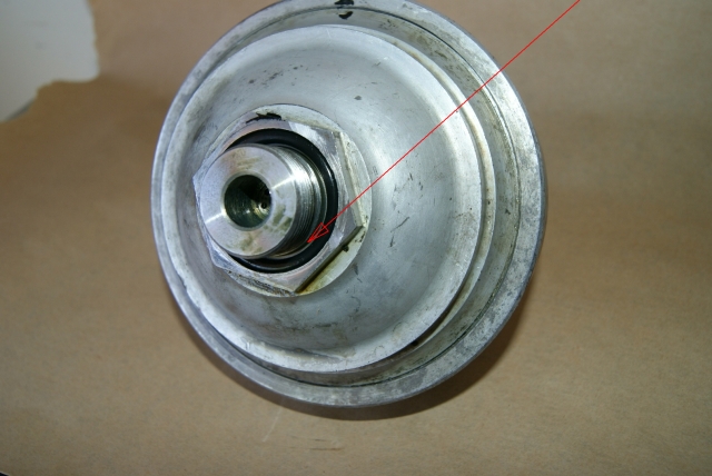 The O-ring is a loose fit. The circular channel it sits in has the following dimensions: Width of channel: 0.15625" Depth of channel: 0.120" Since the channel is oblong in cross section, the cross sectional area is 0.15625 * 0.120 = 0.01875" The O-ring that I removed from the sphere has a diameter of 0.128". This is a rough approximation of it's orginal size as it has now been compressed into an oblongish shape. The figure of 0.128 is arrived at by taking the mean of the two measurements from the "squashed" O-ring. So, the cross sectional area of the retrieved O-ring is (from pi R squared) is 0.0128". This is way below what is needed. No wonder the joint was leaking. The cross sectional area of a 5/32" dia O-ring (0.15625") is 0.01917. This compares very favourably with the required cross sectional area of 0.01875". It appears that the Rolls Royce engineers machined this channel to fit an O-ring with a 5/32" cross sectional diameter. So, no problem until you realise that AS568B standard O-ring sizes do not include 5/32" cross sectional diameters. The closest fit is AS568A-218 with a cross sectional dia of 0.139 and cross sectional area of 0.01517". This is short of the 0.1875" required, but much better than the O-ring I took off the car, supplied with the reconditioning kit. The next size up in the AS568A standard O-ring sizes is a CS diameter of 0.210" which is much too large. So it seems that the AS568A-218 is the only O-ring to go with. Forcing a round peg into a square hole will take up some of the slack. It certainly will be better than the one I used from the reconditioning kit a year ago that was billed as a Crewe part. Has anyone else come across this problem? Geoff. | ||
Brian Vogel Grand Master Username: guyslp Post Number: 420 Registered: 6-2009 |
Geoff, As far as the O-rings go, someone much wiser than I (and an engineer, to boot) once observed: One engineers things such that standard sized seals can be used. No one creates a situation where a custom seal must be created. Since seals well, seal, via deformation it's not uncommon that they're not a perfect fit when lying in their channels but instead become a "perfect fit" when squeezed to become so. All three accumulators that I've put back on to their respective ACVs with a -218 o-ring have not leaked. As far as getting the ACV off of the sphere if the assembly is not on the car, I've always used a heavy hammer to strike the flat spot on the ACV itself that I've had several people who know tell me is there for precisely that purpose. It usually takes a couple of strikes if the things have been together a long time, and no antiseize lubricant was used on the threads, but then you can spin the ACV the rest of the way off by hand. I believe I reversed the process for getting the sphere back on the ACV, but again I was dealing with an "off the car" situation. Back to your question about the RH7860 tool. I know you've read Chapter G, and based on the fact that this thing is used on the hex machined on the bottom half of the sphere it is, essentially, a socket. On the SY-1 series cars, where the bases of the accumulators are, relatively speaking, more accessible it should be significantly easier to attach or remove them from their respective ACVs using a deep socket of the appropriate size. Now, on to a closely related bit of "tool invention" where the measurements will have to be confirmed to assure they're the same for SY-1 and SY-2 series accumulators. I had a pin wrench custom made that must be much like yours: 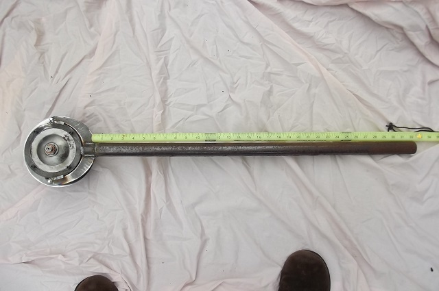 to spin the ring off the accumulator (which is generally easier said than done if you're dealing with one that's not been opened with ages and didn't have antiseize lubricant used when last put together). It is, of course, also used to put the ring back on and to tighten it to mighty high torque. When doing the latter, I had a custom tool set made that use two dirt common sockets and a simple set of two steel disks with the appropriately sized bar stock for the sockets welded on: 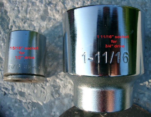 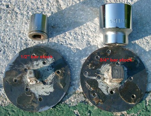 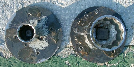 Since the socket that holds the bottom hex is a 15/16" socket, it would seem to me that a deep version of a 15/16" socket is, for all practical intents and purposes, the functional equivalent of an RH7860 tool, based on the description in Chapter G. Brian, who's got more pictures of the bits above in use, but who believes this is probably enough for now | ||
Geoff Wootton Prolific User Username: dounraey Post Number: 201 Registered: 5-2012 |
Hi Brian I understand the point you make about engineers designing parts so that standard size seals can be used. My point is that the standards would have changed since the 1970's when these cars were made. After all, a seal OD 1-1/2", ID 1-3/16" and CS dia 5/32" seems fairly standard. It is just that the new AS568A standard for O-rings does not increment in 1/32" but in 1/16". Hence the sizes for cross sectional diameters go straight from 1/8" to 3/16" leaving out the intermediate 5/32" I shall be using the AS568A-218 when they arrive  and it is heartening to see that you have had no problems with this size. I was merely speculating that the optimum cross sectional diameter was now not used simply because standard O rings of that size are no longer easily available. and it is heartening to see that you have had no problems with this size. I was merely speculating that the optimum cross sectional diameter was now not used simply because standard O rings of that size are no longer easily available. I used the hammer method to undo the acv. Paul Yorke mentioned this in an earlier entry. I will also use this method to re-tighten the sphere to the acv. I used to have an aversion to using a hammer but have come to realise that not only is it sometimes the only way to undo a thread, it often does less damage than using levers etc. Geoff | ||
Brian Vogel Grand Master Username: guyslp Post Number: 421 Registered: 6-2009 |
Geoff, I guess you could be correct about the seals since AS568 originally came out in 1971 and AS568A in 1974. I feel quite certain you will find the performance of -218, 70 durometer, EPDM O-rings (black) quite satisfactory. Brian, who has learned the hard way that sometimes the hard way really is the best way (applying a 3-lb hammer to an accumulator ring, repeatedly, was nerve-wracking but was the only thing that ended up getting it to release). | ||
Geoff Wootton Prolific User Username: dounraey Post Number: 202 Registered: 5-2012 |
Hi Brian I am sure that is the case. I am looking forward to receiving the new seals and getting my car back on the road. Geoff. | ||
David Hughes Experienced User Username: wedcar Post Number: 36 Registered: 7-2004 |
Hi Geoff I think this is the tool you are looking for. Regards David  | ||
Brian Vogel Grand Master Username: guyslp Post Number: 422 Registered: 6-2009 |
David, Have you got a larger image of that tool? This one's so small I can't make any details out and if you try to enlarge it it pixellates so badly you can't make anything out. Brian | ||
David Gore Moderator Username: david_gore Post Number: 1288 Registered: 4-2003 |
Geoff, Just a thought that may help - as you are in the USA, it is unlikely you would think of looking for a metric equivalent to the O-rings in question. 5/32inch is 3.9687mm which is near enough to 4mm. 4mm diameter is a standard metric size so you now have 2 options: 1. Purchase 4mm dia O-ring cord and a tube of O-ring glue to make your own O-ring. 2. Look for the metric equivalent of the imperial O-ring. The following link details metric cord sections available from a US-based supplier: http://www.theoringstore.com/index.php?main_page=index&cPath=368_801&zenid=i5lnde9l8bldrsu6jem2clchq4 Availability of the stocked metric range is on the following link and the website indicates they also do special orders for non-stocked items: http://www.theoringstore.com/index.php?main_page=index&cPath=368 As to the availability of metric EPDM O-rings in the USA, a search for 4mm diameter EPDM O-rings will reveal a number of US-based suppliers. Based on Brian Vogel's post you are looking for a 30.1625mm I.D. x 4mm Dia. actual size based on the imperial dimensions; this equates to a 30mm I.D. x 4mm diameter standard O-ring. | ||
David Hughes Experienced User Username: wedcar Post Number: 37 Registered: 7-2004 |
Gents This is hopefully a better image of the tool required. Regards David 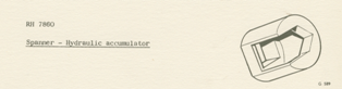 | ||
David Hughes Experienced User Username: wedcar Post Number: 38 Registered: 7-2004 |
Gents Or even this Regards David 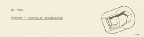 | ||
Brian Vogel Grand Master Username: guyslp Post Number: 424 Registered: 6-2009 |
David, Thanks for the follow-ups. Although I think I see what they were going for with the cut out, I still think a deep 15/16" socket will work perfectly well in this application, particularly for the SY-1 series cars. Brian | ||
Geoff Wootton Prolific User Username: dounraey Post Number: 205 Registered: 5-2012 |
David Yes, thanks for the follow ups. I wondered what this tool looked like. I agree with Brian a 15/16" socket would be just as good and I would guess at a fraction of the price. Geoff. | ||
Geoff Wootton Prolific User Username: dounraey Post Number: 206 Registered: 5-2012 |
David, Looking at metric sizes is a great suggestion but I have now sorted the problem, or to be more precise, Brian has sorted the problem for me. When I separated the acv from the sphere I could immediately see that the O-ring I fitted a year ago from the reconditioning kit was too small. It was a sloppy fit in the housing. I had at first thought the cross sectional diameter was wrong however I now know that it was the outside diameter that was incorrect. Brian very kindly mailed me replacement O-rings - EPDM AS568A-218's and on fitting them into the housing I can see that they are a perfect fit. The OD of the new O-rings is exactly 1.500" wheras the OD of the ones I removed are 1.460" The ones I have removed are obviously compressed so I am guessing they originally had an OD of 1.450" i.e. 50 thou too small. When fitted these O-rings are subjected to the full 2000+ pound pressure of the hydraulic system. This means that every time the engine was started and the system pressurised the under sized rings were stretched by 50 thou to form the seal on the O-ring housing. It is no wonder they eventually failed causing the RR363 leak. Now here's a thing. When I first identified where the RR363 leak was coming from and before removing the accumulators, I ordered the replacement O-rings from a UK company, knowing that they would take a couple of weeks to arrive. These replacements are OEM parts UE35100. When they do arrive it will be very interesting to take measurements from these O-rings to see if Crewe are erroneously supplying the incorrect parts or whether the O-rings I was originally supplied with in the reconditioning kit were a one off error. In the meantime I will be refitting my accumulators with the AS568A-218's. I realise that I may be sounding a little pedantic here, but unless you are the kind of person who enjoys removing accumulators from Rolls Royces then it is crucially important to make sure that these critical O-rings are the correct size and not take it for granted, as I did, that because they are supplied from a reputable company that they are necessarily the right ones to fit. Geoff | ||
David Gore Moderator Username: david_gore Post Number: 1289 Registered: 4-2003 |
"I realise that I may be sounding a little pedantic here, but unless you are the kind of person who enjoys removing accumulators from Rolls Royces then it is crucially important to make sure that these critical O-rings are the correct size and not take it for granted, as I did, that because they are supplied from a reputable company that they are necessarily the right ones to fit." Geoff - even perfectionists make mistakes! The only time mistakes do not happen is when nothing whatsoever is done by individuals or businesses. | ||
Geoff Wootton Prolific User Username: dounraey Post Number: 207 Registered: 5-2012 |
Hi David I do take some comfort from the fact that re-conditioning the accumulators was the very first job I had to do on my Rolls, so one mistake is not too bad. Definitely a baptism by fire. Geoff. | ||
bobuk Unregistered guest Posted From: 94.197.127.23 |
Why are the valve bodies and accumulators fitted where the are Why can't they be fitted where the heater resistors are and resistors fitted else where. Anybody know why The only reason I can think of is in case the accumulators blow up. But this is stupid because if the accumulators did go bang then the front wheel might fall off. I hydrostaticaly tested a boiler once I was meant to go to 450psi got as far 375 and the boiler dropped is bottom No fuss just water every where. The owner blamed me I had just saved his life because if that boiler had blown with steam then never mind a missing wheel we would have been missing everything including the driver and any buildings nearby. I was shown a series of photos when I was an apprentice showing a boiler explosion and it knocked over a 30ft lathe and blew the walls down just a big pile of rubble So I cannot stress enough that you must be carefull with accumulators. These accumulators are well built and Citroen one are the same price so don't bother mucking around with citreon stuff it isn't cheaper. (Message approved by david_gore) | ||
Geoff Wootton Prolific User Username: dounraey Post Number: 214 Registered: 5-2012 |
There are two ports on the "front" of the accumulator control valve (ACV), one for the high pressure line to the distribution valve and the other for the bleed nipple. Does it matter which way round the nipple and high pressure line are fitted? I ask this because in the SY-I manual fig G12 shows the bleed nipples occupying the left hand port on each ACV and in fig G13 (below) they are fitted asymmetrically. 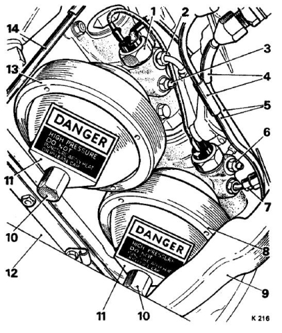 Which diagram is correct? Or is it the case that both ports open into the same chamber so it doesn't matter. I checked out the sectional view in fig G15 but the view is from the other side so these two ports are not shown. | ||
Paul Yorke Grand Master Username: paul_yorke Post Number: 1049 Registered: 6-2006 |
both go to the same void but because air is lighter bleed nipples to the highest port . | ||
Geoff Wootton Prolific User Username: dounraey Post Number: 215 Registered: 5-2012 |
Many Thanks Paul | ||
Brian Vogel Grand Master Username: guyslp Post Number: 518 Registered: 6-2009 |
Now, on to my latest disaster which, if what I'm seeing is correct, sounds eerily like what Geoff had happen several months ago. Today right after the starter worked again and the engine roared to life I sprung a major leak on the left side accumulator. At first I couldn't determine what the source was and I thought I might have somehow forgotten to tighten down the brake pump line to the ACV adapter tightly when I was trying to fix the leaks there. Alas, that was not the case. It appears that I have sprung a leak where the accumulator screws into the valve body. I find this very strange after several months of perfect performance there. I'm not sure if I have seal failure or if I simply didn't get the thing on tight enough and something's now worked loose from vibration. I'm still not having any problems with the other side on this car nor at the same spot on the right side ACV/accumulator junction on LRK37110. Now, to the questions: 1. Is it even worth considering trying to take the accumulator off of the ACV without removing the ACV? 2. If so, how does one go about this? 3. If you can take the accumulator off, what's the best method to get the correct torque (or something near to it) when putting it back on? When doing this off the car I used a heavy hammer to tap the ACV back on to the accumulator much like one does in reverse to get the ACV off of the accumulator. This would not be possible with the ACV on the car. If I've got to remove the whole assembly again I can certainly do it. Since I've done it before it shouldn't be so hellish the second time around, either. Thanks for any guidance. Brian, feeling dejected and as though SRH33576 is punishing me for having bought LRK37110 (which went to the transmission shop two hours ago) | ||
Geoff Wootton Prolific User Username: dounraey Post Number: 255 Registered: 5-2012 |
Hi Brian I can certainly understand the advantage of removing just the sphere since you do not have to disturb any of the hydraulic pipes. I considered this when I had to remove my accumulators. On my SY-I the only option would have been to use a deep socket on the lower hex nut that forms part of the lower hemisphere casting. The big problem, as you will know, is that whichever method you use, you run the chance of loosening the ring on the sphere. I quickly ruled out this option. I figured with 1000 lb pressure in there I really didn't fancy breaching the seal, particularly as in undoing the sphere my head would have been nicely placed for a 1000lb blast of nitrogen/brake fluid. So for me, I played safe and removed the ACV and sphere. I'm curious as to whether breaching the seal is greeted with a hiss of escaping nitrogen or whether you get an explosive evacuation. The other thing I would check is if the leak is coming from the ACV. As you will know, the end of the ACV is sealed with a plug. The center of this plug has a small hole in it and if the seals in the ACV fail, the brake fluid exits through this hole. Since it is just above the sphere, it can appear that the ACV/sphere seal has failed whereas the real cause is the ACV seals. A good test is to dry off the whole area. Run the engine until the brake fluid starts dripping, turn off the engine and just feel the inside of this plug. If it is wet, then it is most likely the failure is in the ACV. Geoff. | ||
Geoff Wootton Prolific User Username: dounraey Post Number: 257 Registered: 5-2012 |
In regard to the seating of ACV against the sphere, when I first removed the accumulators on my car I marked the position of the ACV against the sphere with a paint mark. On screwing the ACV back onto the sphere I could see these paint marks matched up perfectly. Paul Yorke said in a previous entry you can feel when the sphere/ACV has seated. I found this to be the case. Once it has seated, further tapping with the mallet did not achieve any further tightening. This was also the case when I subsequently replaced the undersized O-rings I had been supplied with from the re-conditioning kit; the paint marks matched perfectly. Once the two components are seated, they're seated. When you stated "if I simply didn't get the thing on tight enough" I would answer that it was quite definitely tight enough. If they were not seated properly then the leak would have shown immediately. I also doubt that the ACV/Sphere loosened with vibration. Is that not part of the purpose of the retaining plate that bolts to the sump. A curious fault. I know you have the correct sized O-rings. I will be very interested in your follow up to reveal the cause of this leak. Geoff | ||
Brian Vogel Grand Master Username: guyslp Post Number: 529 Registered: 6-2009 |
Following up on this. Today's the first opportunity I've had, given the combination of ungodly hot/humid weather and life events, to get back to work on SRH33576. Having her front end up in the air and the left tire off gave me excellent access to view the accumulator assembly and it's clear that the gusher is coming from the juncture between the accumulator and the valve body. I've already mentally committed to a complete removal of same in order to separate them. I am hoping this might be some kind of seal failure, possibly because I didn't get this accumulator screwed in tight enough so that the seal eventually gave way, but given what I can remember about the process I'm doubting it. What I'm wondering is if there is any way that the control valve could fail such that once maximum pressure is reached the fluid is not getting shunted back to the reservoir return line? When the car is in the "Run but not running" key position and you do the "quick brake pedal pump test" you can see that the fluid levels in the respective reservoirs do increase significantly as you deplete the accumulators, but that fluid shouldn't be getting back there via the control valve to reservoir return line in this situation, should it? In any case, once I have this out I do not want to put things back again only to determine the problem was/is with the ACV and not a seal. I'm presuming someone here can probably tell me whether this is probable, remotely possible, or virtually impossible. Brian, who will be posting photos once I've got things out and apart | ||
Brian Vogel Grand Master Username: guyslp Post Number: 534 Registered: 6-2009 |
The next installment, including photos . . . I appear to have a seal failure that, based upon appearances, is the result of it somehow having been "shredded" when the accumulator was screwed back into the valve. I say this because what you will see is not "gooey"/partially dissolved in any way - you can still snap the bits like rubber bands. Absolutely none of this was in evidence at the time the ACV assembly was installed. It's slowly been pushed out by the fluid pressure. 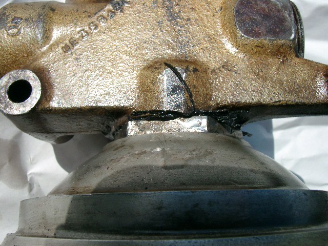 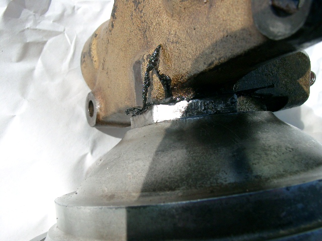 It's exactly where I thought it would be in that all of the fluid was coming out from the engine-facing side of the ACV and then running around the front of the accumulator. More photos once I get this into a vice and the two major components knocked apart. Brian | ||
Paul Yorke Grand Master Username: paul_yorke Post Number: 1083 Registered: 6-2006 |
That looks nasty! Where did you get the seals? Did you lubricate them before tightening? Vice should not be needed. Hold the sphere in one hand , tap the valve around with a copper hammer. Cover the ports to stop brake fluid being ejected. | ||
Brian Vogel Grand Master Username: guyslp Post Number: 535 Registered: 6-2009 |
Paul, The seals were purchased from smallparts.com, now AmazonSupply.com, several years ago. This is the only failure I've experienced. The same seals are working just fine on two other accumulators in my "fleet" and on some unknown number for the various folks I've sent these to. I imagine I'd be a very unpopular person were these to have consistently failed in this way, since I've circulated quite a few of them. I have to believe I lubricated the seal before tightening (that's my habit with these things, but it's so long ago I can't be certain). I've not used a copper hammer in the past, but may have one. The vice is just a convenience for me (and a safety device, too, since I have lost grip on heavy objects like this one before). I guess my consolation is that It doesn't appear to be some sort of horrific failure of the ACV after rebuilding it. Brian | ||
Geoff Wootton Prolific User Username: dounraey Post Number: 266 Registered: 5-2012 |
Hi Brian Very strange. It's almost as if the accumulator got too hot and the rubber melted. I can't imagine that this is the case. I had my car jacked up yesterday when I was removing the speedo cable and took the occasion to check my accumulators which were assembled with the O-rings you sent. They are both bone dry - no trace of this problem so I doubt it is the O-rings, unless you had a single rogue one in your supply. Will be interesting to see the photos when you have separated the sphere from the ACV. Geoff. | ||
Brian Vogel Grand Master Username: guyslp Post Number: 537 Registered: 6-2009 |
Got the ACV assembly apart using the technique suggested by Paul, except that I used my 3-lb steel hammer. Several swift taps, not even particularly heavy strikes, and the ACV was ready to screw off by hand. Now, on to additional photographic documentation from the disassembly: 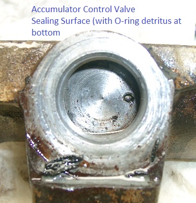 Before o-ring removal from accumulator sphere sealing groove: 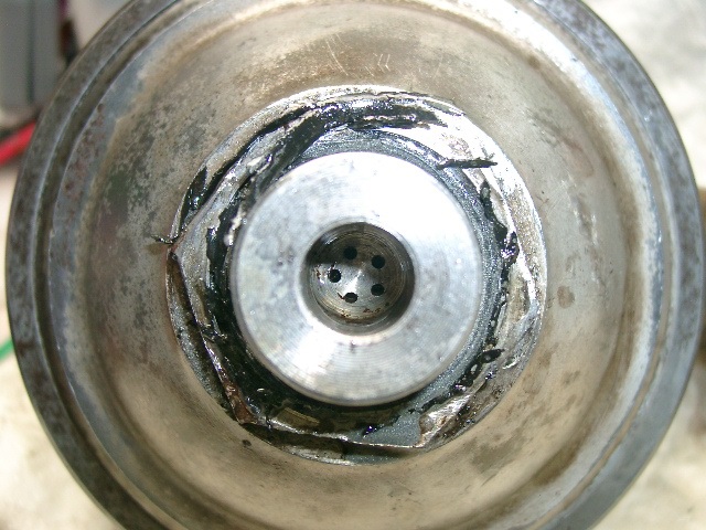 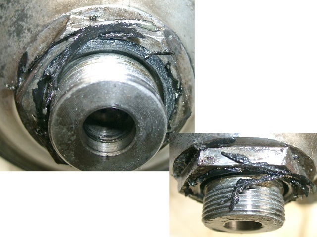 Both sides of O-Ring after extraction from groove: 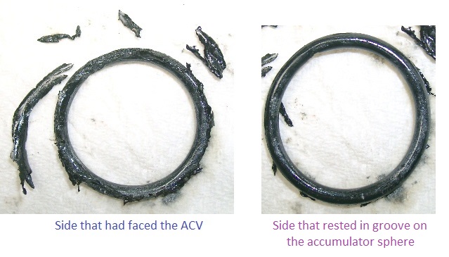 I have to believe that this is the result of a bad O-ring in the supply. That or I used just a dab too much anti-seize on the accumulator threads and this eventually caused the O-ring to break down on its upper surface. The latter has not occurred on either of the other ACV assemblies I put together using anti-seize, though. I am positive that I lubricated the O-ring liberally with fluid before screwing everything back together this time. Brian | ||
Geoff Wootton Prolific User Username: dounraey Post Number: 267 Registered: 5-2012 |
Brian What is the condition of the sealing surface on the ACV. It is hard to tell from the photos. Is it flat and smooth. If it is badly scored it will tear the O-ring as the sphere is screwed on to the ACV. Just a thought. Geoff. | ||
Brian Vogel Grand Master Username: guyslp Post Number: 540 Registered: 6-2009 |
Geoff, While it's not "mirror smooth" it also doesn't seem to be "chew the thing apart" rough. Since the thing is still on my workbench, and it's easy to knock the ACV off again, I think I'll do that to see what things look like after they've simply been screwed together. It seems highly unlikely to be the cause, but I'd rather check again now than have to go through this entire process again. Brian | ||
Geoff Wootton Prolific User Username: dounraey Post Number: 268 Registered: 5-2012 |
Brian, It really is looking like you had a rogue O-ring. Geoff | ||
Paul Yorke Grand Master Username: paul_yorke Post Number: 1086 Registered: 6-2006 |
looks like contamination or wrong material. castrol red rubber grease on brake fluid rubber components. or brake fluid. | ||
Brian Vogel Grand Master Username: guyslp Post Number: 541 Registered: 6-2009 |
Paul, I have no idea what "Castrol red rubber grease" is. The only things used in "the area" when this was put together originally was YAK363/OMAR363 (whichever term you prefer) on the O-ring and a bit of Permatex Anti-Seize Lubricant (not the copper variety) on the accumulator sphere threads. This is what you see as the ever so slightly silvery-grey stuff in the photos. It tends to "distribute" itself when you're taking things apart and have fluid to move it about. As I mentioned earlier, I used this on all three sets of sphere threads back when I was putting all of these back together and only this one has failed. Brian | ||
Brian Vogel Grand Master Username: guyslp Post Number: 542 Registered: 6-2009 |
Here's what things looked like when I knocked the ACV off of the accumulator just a few minutes ago after things had been sitting on the workbench overnight: 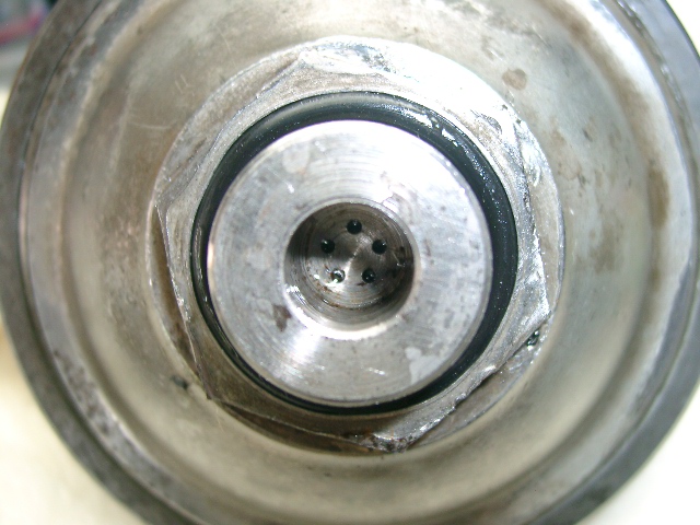 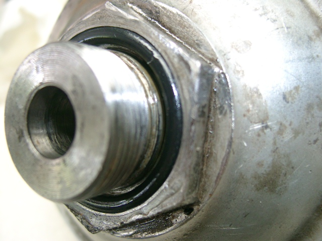 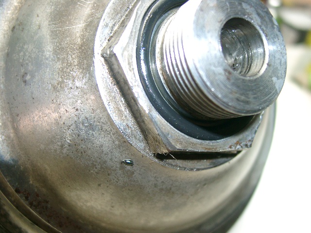 After all this I have to believe I had either a defective O-ring or that somehow an O-ring made of something other than 70 durometer, black EPDM made it into the bag with all the others. There's no evidence of mechanical damage of any sort to the seal from putting the ACV and accumulator together. I tossed the one that was in there, popped in another lubricated AS568A-218 EPDM O-ring, and put it all back together. After a brief break, including this post, it's out and under the car to get this thing reinstalled again. Brian | ||
Geoff Wootton Prolific User Username: dounraey Post Number: 269 Registered: 5-2012 |
Brian If the edges of the hex nut are raised at all it will prevent the acv seating properly. 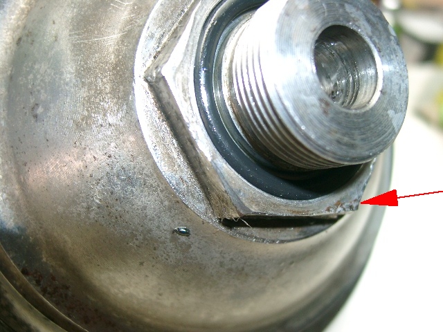 I'd check this before re-fitting. Geoff | ||
Brian Vogel Grand Master Username: guyslp Post Number: 543 Registered: 6-2009 |
Geoff, Too late, it's already on the car. I doubt this is an issue, though, since I had no leak for months after the initial installation and that leak appears to be a function of seal breakdown. All I've got left to do is getting shorter bolts for the exhaust manifold clamp such that a socket can be used from beginning to end when tightening the nut down or removing it, then get the clamp back on. Then it's on to refilling, checking for leaks, and bleeding the system 2 end of things again. Brian | ||
Richard Treacy Grand Master Username: richard_treacy Post Number: 2868 Registered: 4-2003 |
Practically any brand of red rubber grease is fine. Use it and you may be confident. Without it, expect trouble. This Protex-branded product supersedes the PBR stuff used for decades by most specialists in DOT3/4 and SY RR363 systems. RT. 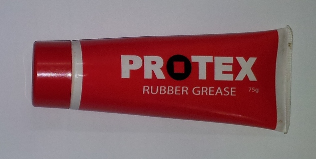 | ||
Richard Treacy Grand Master Username: richard_treacy Post Number: 2869 Registered: 4-2003 |
To explain the O-ring problem. In the mid-1980's, a bright chap at Crewe suffered when a he blinked and ordered a batch of nitrile O-Rings of the same size as the ones applied to the SY spheres. Nitrile is of course completely the wrong material for these glycol fluids. For a few years those spare parts failed after just months of service, disintegrating just as the ones that Brian pictures. Once the chap left Grubbyland and became an investment banker the O-ring pipeline was cleared the suffering ceased. I was a victim of the O-ring disaster back then. | ||
Brian Vogel Grand Master Username: guyslp Post Number: 544 Registered: 6-2009 |
Interesting stuff, this red rubber grease. It seems closely related to silicone grease, but from what I can find it's vegetable based. This must be one of those "depends on where you are located" things in terms of commonality of use. I've never seen the stuff, nor heard of it, prior to now and generally lubricate whatever rubber parts are being installed with the fluid that will be surrounding them in their working environment. Does anyone know just how "sensitive" EPDM is to petroleum-based products? Virtually any anti-seize lubricant I've ever found has a petroleum base, and I've come to use a tiny bit of it on virtually every threaded connection I assemble, including brake line connections, particularly since those threads are outside the "zone of fluid" when operating. At this point things will stay as they are since it would be as big an issue to remove them again now as later, and based on "two out of three" it seems unlikely that there will be a later in the near future. Brian | ||
Brian Vogel Grand Master Username: guyslp Post Number: 546 Registered: 6-2009 |
Well, you could knock me over with a feather, but not a single drop, ooze, or gush anywhere. God willing this will last. Now that I know that it's the rear two calipers on the front wheels and the lower cylinders on the rear calipers that must be bled that's next on the list. Brian, who hates that sense of waiting for the other shoe that seems constantly there lately |