| Author | Message | ||
Jeff Young Prolific User Username: jeyjey Post Number: 127 Registered: 10-2010 |
My fans stopped working some time back, except on defrost. Digging into the fan speed controller circuit diagrams I found a couple of interlocks: the controller is disabled if the servo is calling for hot air and (a) the temp switch says the water is cold or (b) the lower quantity flap is not open. Unplugging the temp switch (the lower of the two on the thermostat housing) made no difference. Unplugging the lower quantity flap microswitch (under the steering column) gave me fans again. Further inspection revealed that the pivot pin in the lower quantity flap control arm had seized, and doubtless after some number of cycles, snapped the "shepherd's crook" coming down from the lower quantity flap servo motor. The circlip came off the pivot pin easy enough, but it took me over an hour (in some rather uncomfortable positions) to get it free of the control arm. I stuck it in a drill motor and gave it a spin with 320, 450, 600 and then 800 grit sandpaper, gave it a coat of grease, and it now spins freely. I thought I might be able to remove the shepherd's crook with the servo in place, but you'd need to get a pair of 4BA spanners up there, and that's just not going to happen. However, as luck would have it, 4 bolts allows one to lower the relay "stack" to the door side of the steering column, after which there is decent access to the three philipps screws holding the servo in. Now that I have the servo out, should I disassemble it and re-grease, etc., or leave well enough alone? Paul, do you have shepherd's crooks available? (This one is 4-3/4" from the top of the eye to the end of the thread, if there are different sizes of them.) Jeff. | ||
Brian Vogel Grand Master Username: guyslp Post Number: 304 Registered: 6-2009 |
Jeff, Sorry to butt in to your thread, but we're both "calling Paul" and for the same reason. I described the same issue as you have that's happening on my Silver Shadow II. Paul Yorke wrote in another thread: PS otter switches are also fitted in the thermostat housing, a 44 degree one for the air con fan cut out and a 105(ish) one for the auxiliary engine cooling fan. And one in the air con intake unit to turn off the compressor if ambient air is below zero. I have several questions about these switches: 1. Where are they documented in the spare parts manual. I know exactly where they are on the car, but I can't seem to find them in the parts manual. 2. Can these be removed without causing a flood of coolant? I'm not sure if they're actually "in the flow" or rely on conduction through the thermostat housing and can just be "popped off." 3. Can they be tested off the car using a pan of hot water? I would imagine there should be no continuity when cold but that once heated there would be between the switch leads. 4. Are they potentially repairable or is this an item that once dead is absolutely toast? This is the next "big project" on SRH33576 after I get that *^%$*#$ leak at pump input pipe/accumulator control valve adapter resolved. Brian | ||
Jeff Young Prolific User Username: jeyjey Post Number: 128 Registered: 10-2010 |
Hi Brian, Electrical section; ACU subsection (page K21/3). I believe removing one will result in coolant spillage. I can't think of any reason why one couldn't test them off the car, but I believe you have the sense backwards (continuity when cold; open when hot). They are rather dear, so it would be nice if they were repairable. I've never had one go south on me though, so I can't speak from experience.... Cheers, Jeff. | ||
Jeff Young Prolific User Username: jeyjey Post Number: 129 Registered: 10-2010 |
(Oh, and there's also one in the air intake for the weakener. Parts book Carbutetter section; Air cleaner and silence subsection; page B3/8.) | ||
Brian Vogel Grand Master Username: guyslp Post Number: 305 Registered: 6-2009 |
Jeff, Thanks much!! Since the car in question is due for a coolant change I can check all this out during that process. My presumption as to the no continuity cold and continuity when warmed up is due to the fans coming on once it is. Of course, I realize that circuits can be designed that turning one thing off (no continuity) turns something else on [e.g., the low coolant light] but they generally seem to be the exception than the rule. I'll look for a state change from one to the other. If it stays the same I know it's dead (and that I can safely dissect the thing to determine its workings at the very least). Brian | ||
Paul Yorke Grand Master Username: paul_yorke Post Number: 991 Registered: 6-2006 |
PS otter switches are also fitted in the thermostat housing, a 44 degree one for the air con fan cut out and a 105(ish) one for the auxiliary engine cooling fan. And one in the air con intake unit to turn off the compressor if ambient air is below zero. I have several questions about these switches: 1. Where are they documented in the spare parts manual. I know exactly where they are on the car, but I can't seem to find them in the parts manual. Engine inlet manifold thermostat housing A7 2. Can these be removed without causing a flood of coolant? I'm not sure if they're actually "in the flow" or rely on conduction through the thermostat housing and can just be "popped off." No, they have a cork gasket and are in a 'thimble' in the water. The gasket will fall apart. The screws might break. The water will leak. 3. Can they be tested off the car using a pan of hot water? I would imagine there should be no continuity when cold but that once heated there would be between the switch leads. Yes , but do not immerse them. 4. Are they potentially repairable or is this an item that once dead is absolutely toast? They are rolled into the casing but you can pull them out ( More likely that they have fallen apart. They are a bi-metalic over centre switch that 'pings' when they heat up, so adjusting them would be tricky. They are also an unnecessary item, especially in hot countries. Who wants to jump into their sun baked car and wait a few minutes for the air can fans to work? You can override it with the facia switch etc , but should you need to? This is the next "big project" on SRH33576 after I get that *^%$*#$ leak at pump input pipe/accumulator control valve adapter resolved. | ||
Brian Vogel Grand Master Username: guyslp Post Number: 306 Registered: 6-2009 |
Paul, Thanks for all that. When I first saw your response I thought, "And the point in quoting me verbatim is?," until I realized that you'd tacked your responses to the end of each question. One thing this forum lacks is a good "quotation manager" that lets one easily differentiate quoted material from response. Brian Moderator's Advice - This is possible using the text colour box on the top of the posting screen. Just select the colour, enter the text and if you need to revert to ordinary text, just select "black" and continue. One limitation is you cannot highlight text and then select colour as the code will appear at the end of the post. You have to enter the colour, cut it from its position and paste it in the appropriate location. If you want subsequent text to be black, just select black, cut the format code from the end of the post and paste it in the appropriate location. Have highlighted Paul's responses above using this technique. | ||
Brian Vogel Grand Master Username: guyslp Post Number: 308 Registered: 6-2009 |
Well, here's a photo of the two otter switches (on the right side, stacked above each other) and some other sensor over to the left: 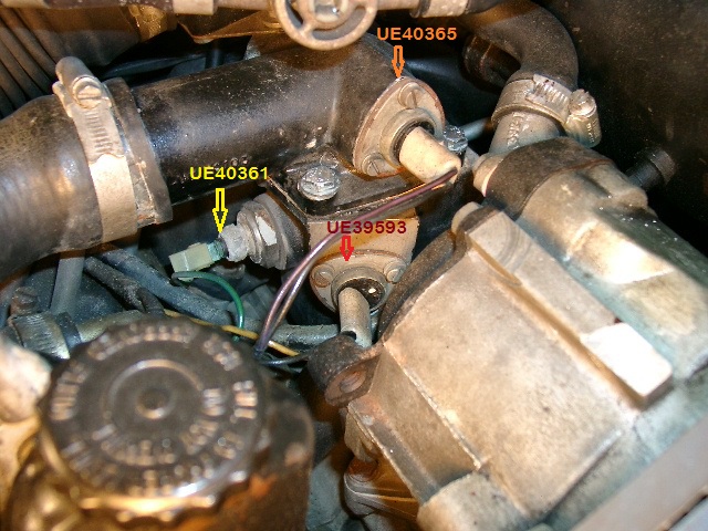 The problem for me is that these are "documented," and I use that term loosely, on parts manual pages that were printed with illustrations and numbers only, but no key describing what parts those numbers represent. Am I safe in presuming the otter switch that allows the AC fans to kick in is the lower one (UE39593)? If so, then what is the function of UE40365? Also, what's sensor UE40361? Brian, sorry for the ongoing questions, but the reference material leaves questions unanswered | ||
Paul Yorke Grand Master Username: paul_yorke Post Number: 992 Registered: 6-2006 |
Coolant gauge transmitter. If you look closely their temperature rating is marked on the black plastic. 44 for A/C 105 ish for Aux cooling fans. | ||
Jeff Young Prolific User Username: jeyjey Post Number: 130 Registered: 10-2010 |
Hi Brian, Yes, the lower one is the fan speed controller lockout. It disables the fans when in screen mode (but not defrost) and the engine coolant is below 44�C, and the lower quantity flap is not fully open. According to page C4-1 of TDS4200, this "prevents cold air from being blown into the car when hot air is required and also prevents a sudden surge of air to the screen causing considerable noise which, as well as being undesirable, would also be unexpected." The upper Otter switch is for the supplemental electric fan in front of the radiator. (That one, interestingly, is closed-when-hot. Most of the others are open-when-hot.) It doesn't seem to be documented anywhere, aside from appearing in the lower centre of the wiring diagram. UE40361 is the transmitter for the coolant temperature guage (in the 4-in-1 instrument). Cheers, Jeff | ||
Jeff Young Prolific User Username: jeyjey Post Number: 131 Registered: 10-2010 |
Ooops, cross-posted with Paul. Oh well, there are a few other bits in there that might be useful, or at least entertaining. ;) Jeff. | ||
Brian Vogel Grand Master Username: guyslp Post Number: 309 Registered: 6-2009 |
Paul & Jeff, Thank you both. In the case of these "scantily documented" bits more is better!! Brian |