| Author | Message | ||
Bob Reynolds New User Username: bobreynolds Post Number: 6 Registered: 8-2012 |
There must be hundreds of relays on these cars, dotted about all over the place. Wherever you look, there seems to be a group of relays hidden away; but no labels, and no clues as to their purpose. Is there some document that tells you where each relay is situated? Or has anybody made a list with this information? | ||
Jeffrey McCarthy Grand Master Username: jefmac2003 Post Number: 328 Registered: 5-2007 |
Bob -in section M10 (electrical) of the workshop manual is a section on relays. http://rrtechnical.info/sy/tsd2476/13.pdf It shows what the relay types are and names by position each relay in the main engine bay bank. This will name either 6 or 10 of them depending on the year of your car. On right-hand drive cars this is under a metal shield immediately in front of the driver. The ones under the dashboard and elsewhere it's a matter of noting the colours of the attached wires and referring to the theoretical wiring diagram. I label all mine as I find out what they're for. One had me stumped until I looked at a diagram for a slightly later car than mine and realised it's for the windows. If you can blow up the wiring diagrams for your car and stick the pages together it makes it a little easier. Use the high-resolution one as the letter codes on the diagram can be hard to read and have handy the list of codes (U=blue, N=brown S=slate; the rest are the first letter of the colour P=purple for example) to be found in the manual in the wiring diagrams section. The relays are all Lucas I think except for the stop-light failure ones in the boot which are small white plastic things. Also if you trawl through the spare parts section blown-up diagrams you can often spot a few there. What year/engine number is your car? I'll be under the dash tomorrow and will ID some of them for you while I'm there. | ||
Jeffrey McCarthy Grand Master Username: jefmac2003 Post Number: 330 Registered: 5-2007 |
Bob - I figured out that your car is a 1975 from your other post. Under section K12 of SS Spare Parts is a section called 'Interior Electrical fittings' http://rrtechnical.info/SY/spare/6580_4/IMAGES/k/K12.pdf Some of the relays are here - especially the under dash right-hand side ones. There appears to be no available drawing for the bank in the centre of the dash; however if you scroll down and look at the SSII diagram you'll get an idea of what they're for - mostly warning lights I think. Our cars, being late in the series one Shadows had some modifications from the earlier diagrams so it's always useful to go to a later car and see if that wire or component that's not on your diagram is to be found there. Modifications were often made to the Corniche before being used on the saloon cars so that's a useful place to look as well. Some people have put the diagrams on an old laptop to keep in the garage or car for easier reference when they're working. | ||
Bob Reynolds New User Username: bobreynolds Post Number: 9 Registered: 8-2012 |
Thank you for that info. It's a shame that there's no proper list anywhere. Some of these relays seem superfluous to me. Quite honestly, how necessary is it to dim the Low Fuel warning lamp when the lights are on?! There's an entire circuit devoted to this dubious function. It's supposed to be a warning lamp!! | ||
Jeffrey McCarthy Grand Master Username: jefmac2003 Post Number: 332 Registered: 5-2007 |
Ah but Rob - if it just came on and just stayed on you might think that you have to rush into the nearest service station to get fuel!! The fader is there, like a private secretary, to give you your next few days schedule lest there be something other to do. It starts when there's about a third of a tank of fuel left !! Which as it happens has now become probably handy advice given their age - I'm told it's best to keep it at least at that level to avoid putting 30 odd years of tank sludge through the carburettors. I'll be working on those circuits as I said, hopefully next week, to try and get the buzzer/ test-circuit to work: I'll keep you posted. I recently revisited the 'key left in ignition when door opens' circuit, which I restored. I suspect it's been deleted on 90% of Shadows because unless the microswitch is within minus 1MM of tolerance the alarm either doesn't work at all or it does - permanently!! | ||
Bob Reynolds Experienced User Username: bobreynolds Post Number: 12 Registered: 8-2012 |
I have removed the Switchbox now, and it's a bit of a mess behind there. Scotchlok connectors and tape all over the place! It looks like a previous owner has disconnected the driver's interior light switch and used it for something else, but I've no idea what because it doesn't appear to do anything. It is patched up to one of the relays behind the Switchbox, so that relay has also been rewired and has lost its original function. Despite the information on this page, I still have no idea what the 4 relays behind the Switchbox are for. The wiring colours are either inaccessible, ambiguous, or don't match the wiring diagram. I worked out that one is the Hazard Flasher. I have reconnected the switch to the driver's interior light, but now I have a 'spare' relay and no idea what it should do! | ||
Jeffrey McCarthy Grand Master Username: jefmac2003 Post Number: 334 Registered: 5-2007 |
Bob, I've spent the morning playing behind the dash and will have some photos to post later tonight. Many Shadow driver's light connections have been changed because owners were unaware that it is turned on by pulling the headlight switch towards you; mine was bridged at the light fitting! There is no relay on this circuit - it is a direct power feed to the bulb. Tonight I'll post the wire colours. It is unlikely that someone has taken the switch apart but anything's possible - from memory it feeds (is fed by?) the purple wire that comes out the side of the barrel; the only wire to do so. I'll check this as I said and get back. One of the relays is window related - the one with the yellow/black cotton wire. Scotchlock connectors are my pet hate - as are those cheap plastic connectors without a straining crimp. | ||
Jeffrey McCarthy Grand Master Username: jefmac2003 Post Number: 335 Registered: 5-2007 |
Bob - some of my photos weren't clear enough to use - I'll go and take some more. On my car there are only 3 relays there: The Hazard relay is mounted in the triangular bracket farthest to the right. The Window relay and The Blower motor relay are mounted behind the speedo with the pins pointing upwards. The diagrams for my car (1973 spec) don't show the window relay at all - I found it on a later diagram. I assume you are using the one labelled "All cars built to 1975 spec" ? For future reference: There is a relay behind the glovebox above the Window Cutout otter switch (black box with red dot, held in place by the metal bracket in the first photo) - I don't know what this is for: this however is the area where you bridge the windows wires to be able to use them with the ignition off - you don't need to remove the glovebox. 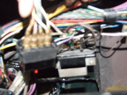  There are three relays in the centre of the dash. These I assume are to do with the warning lights. The white plastic box is the Coolant Level amplifier. 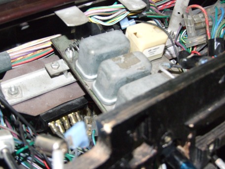 Just visible to the right in this photo is one of the 2 Drivers side relays behind the speedo - these are held in place by some bolts and spacers with nuts behind the metal bracket. The relay on the left is the window one and the other is blower motor. 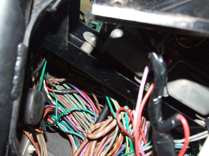 | ||
Jeffrey McCarthy Grand Master Username: jefmac2003 Post Number: 336 Registered: 5-2007 |
The right-hand dash relays have proven almost impossible to photograph. However looking at the diagram, I think the 3 in the centre of the dash are: Coolant Probe; Warning Light Test; and Fuel Dimmer. In which order I know not. Incidentally the last photo above is taken from below with the fuse box down. | ||
Jeffrey McCarthy Grand Master Username: jefmac2003 Post Number: 337 Registered: 5-2007 |
Rod In the spirit of "if it doesn't exist - invent it!" perhaps we can turn this thread into the needed list of relays, their function and their location. Eventually we can compact the information into a handy guide. There are also some relays in the centre console (photos maybe next week). These are I assume to do with the air-con system and/or the the old 8-track & radio. Going through the parts list there are several more to be located and/or identified in the interior. The problem seems to be that late Shadow 1s have some of the components of the Shadow 2 - the centre dash circuit board with relays in photo 3 above doesn't appear in the Shadow I parts list but does at the bottom of the page in the Shadow II diagram. (Page 13) although with slightly different additions like 'ice warning'. http://rrtechnical.info/SY/spare/6580_4/IMAGES/k/K12.pdf Among the relays listed in parts for Shadow I that it would be useful to know about are: 82 - UD9270 RELAY Anti-thief 74 - UD9270 RELAY Delay unit 50 - UD9270 RELAY Ignition key warning 49 - UD9270 RELAY Compressor Clutch Fuse & Blower 7 - UD9270 RELAY Master Switch 6 - UD9270 RELAY Hood The part number UD9270 indicates that these are all the same type of relay (see page M68 of Chapter M of the manual for the list of types) I assume some of the above have been deleted at various stages of production - my key warning circuit for example consistes of a micro-switch on the lock; a buzzer and two wires. If at any stage anyone working on the cars can identify a relay please post information about it here - crucially indicating your engine number. Mine is SRH20280 1974 right-hand drive. | ||
Jeffrey McCarthy Grand Master Username: jefmac2003 Post Number: 338 Registered: 5-2007 |
Oddly enough I can't find the Windows Relay on the Interior Electrical Parts list - perhaps it's eye-strain. In any case it looks like this. 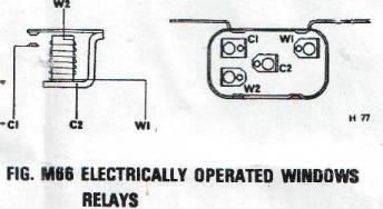 On the Shadow 2 it seems to be located on the left side (RHD cars | ||
Jeffrey McCarthy Grand Master Username: jefmac2003 Post Number: 339 Registered: 5-2007 |
Hazard Warning Relay 18 - UD13722 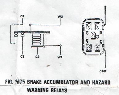 | ||
Bob Reynolds Experienced User Username: bobreynolds Post Number: 13 Registered: 8-2012 |
Your information is very welcome indeed. My car is SRH 21909. Just a few after yours. I can identify the 3 relays in the centre of the dash, as I have had all that PCB out to trace the wiring. None of my warning lights worked at all, now they all work (smile). The 3 relays are, from the back: Warning Lamp Test Relay; Fuel Warning Dimmer Relay; Coolant Probe Relay. The circuit in the white plastic plug-in box is the Coolant Level Amplifier. (This became the Screenwash Amplifier in the Shadow 2). There are 2 spare relay positions, I think one is for the Ice warning. The Warning Lamp Test Relay is operated by the starter switch and puts Earths out (through diodes) to all the warning lamps to check the bulbs (Note that it ONLY checks the bulbs, not the wiring or sensors). The Fuel Warning Dimmer Relay is operated whenever the lights are on, and puts a 30 ohm resistor is series with the Fuel warning lamp. The resistor is underneath the PCB. The Coolant Probe Relay is operated by the Hot Metal Sensor, and also by the Warning Lamp Test Relay. It just disconnects the coolant probe from the circuit so that no coolant is detected. This has the effect of lighting the Colant Level lamp. The wiring diagram I am using is "RHD Saloon & LWB Non-Division Cars from SER.No.16214 (c)1974" I believe this is the correct one for our cars. Everything has matched so far (almost!) The 1975 one you mention is probably late 1975 with the electronic ignition and no Master Cylinder. One thing that is missing from my car is the Part-Brake Failure Warning Light. If any of the 4 brake warning lights come on, according to the diagram this is supposed to also illuminate a 'Part-Brake Failure Warning Light'. But if it is fitted, I've no idea where it is! | ||
Jeffrey McCarthy Grand Master Username: jefmac2003 Post Number: 340 Registered: 5-2007 |
While we're on the subject of locating devices. Does anyone know physically where on the car the Height Control Switch is located? I'm assuming the HC solenoid is in the boot area somewhere. I'm trying to trace the green plastic wire from Fuse 11 to put back my fuel gauge/warning lamp circuit and the diagram shows they are linked. Shadow I 1974 SRH20280 | ||
Paul Yorke Grand Master Username: paul_yorke Post Number: 858 Registered: 6-2006 |
just quickly, valve is under the car on the rear subframe close to the prop shaft. feed from park and neutral switches, most likely on the gear selector actuateor..also a feed from the interior light switches on earlier cars. | ||
Bob Reynolds Experienced User Username: bobreynolds Post Number: 14 Registered: 8-2012 |
Jeffrey, I am intrigued by your mention of the Key Warning Buzzer. I would like to get this working on my car if possible. The Red/Brown wires seem to be present on the Switchbox. Whereabouts is the actual buzzer? The diagram shows this buzzer is also connected up to a 'Switchbox Park Switch'. This appears to be a separate switch from the lighting switch wafers. Does this mean that the buzzer also sounds when you open the door with the lights on? This facility would be extremely useful, so I would like to get it working, even if I have to install my own buzzer and wiring. | ||
Jeffrey McCarthy Grand Master Username: jefmac2003 Post Number: 341 Registered: 5-2007 |
My buzzer had been deleted, as I suspect many were. I just used an ordinary 2 pin buzzer although I searched for an interesting chime to no avail. I taped mine on top of the steering column shaft but anywhere the wires will fit should do. The wires were also present on my switchbox but the microswitch was dead. It is a very small microswitch bolted on directly beneath the key barrel - when the key is inserted a tiny pin descends and pushes the button. Most likely if yours hasn't been disconnected the switch will have slipped over time as the bolts loosened - they are tiny nuts and bolts so do the pillow case trick while you're working on it. You may need to solder the wires to the switch - be aware of the clearance to the metal barrel as it's a closeish fit. Also use a bit of locksmiths graphite - the little pin on mine needed loosening up to avoid sticking on. You have to experiment a few times with getting the microswitch exactly positioned right, I tightened the tiny bolts and then put a small dab of silicone between the switch case and the mount to stop it vibrating loose; easily removed if the switch needs changing. I have half a dozen spare of the switches - if you need one just email me at jefmac2003@yahoo.co.uk and I'll pop one in the post. I'll upload a picture and/or dimensions for future reference - they are smaller than the windows etc. microswitches and are probably available at Jaycar. p.s. I installed a headlights left on alarm as well while I was at it; not as simple as just following the instructions on the box, of course, as our door switch wires are permanently live. I wired it to come on if the headlights are on and the ignition is off. I can disconnect it from the fusebox in emergencies. | ||
Bob Reynolds Experienced User Username: bobreynolds Post Number: 16 Registered: 8-2012 |
Fortunately, the key switch is present and working on my car. This switch also works the transmission brake on the gearbox. You can hear it engaging when you remove the key. The Key Warning Buzzer is also activated when the 'Switchbox Park Switch' is operated and the doors opened. Does anybody know what the Switchbox Park Switch is? | ||
Jeffrey McCarthy Grand Master Username: jefmac2003 Post Number: 342 Registered: 5-2007 |
I suspect this microswitch is it. Nowhere can I find a label 'Key Warning Buzzer switch' - the only indication is the wire connections to the buzzer and this diagrammatic indication that the pin exists. Wouldn't be the only switch on the car that has a double function.  | ||
Jeffrey McCarthy Grand Master Username: jefmac2003 Post Number: 343 Registered: 5-2007 |
Incidentally Bob - I realised what you were saying about the Fuel Dimmer circuit - I always thought it was a time delay function; my warning light starts to come on and off about 1/3 full with increasing frequency as the level drops. I realise now that this is because I drive on very hilly bendy roads and this probably happens as a result of the petrol sloshing about in the tank. Pity - I thought it was a neat idea to give an early and then more urgent warning. If it just dims the warning light at night (the only panel lights that ARE bright enough) what a bizarre amount of dash space to occupy doing it. | ||
Bob Reynolds Experienced User Username: bobreynolds Post Number: 18 Registered: 8-2012 |
"If it just dims the warning light at night (the only panel lights that ARE bright enough) what a bizarre amount of dash space to occupy doing it." Not only that, but the relay is operated, wasting power and generating heat all the time the lights are switched on; irrespective of the amount of fuel in the tank! The switch in your diagram is the Key Switch. If you trace the RGP wire you will see that it goes to the Gearbox Actuator. But there is another switch just off your diagram at the bottom labelled 'Switchbox Park Switch'. It is not part of the Switchbox. This switch also goes to the buzzer, via the same wire. | ||
Jeffrey McCarthy Grand Master Username: jefmac2003 Post Number: 353 Registered: 5-2007 |
Here is a better photo of the window lift cutout and associated relays and control units found above the lower glovebox/cubby on a Shadow I. The 2 fuses are for rear Foglights if fitted, one of the control units is the courtesy-light delay and I'm not sure about the rest. The white box on the right is labelled part no: UD18587. 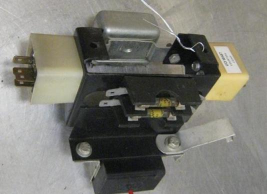 | ||
Jeff Young Frequent User Username: jeyjey Post Number: 98 Registered: 10-2010 |
UD18587 is the courtesy light delay. In the Shadow II, there's another white box above the fuse panel and below the glovebox that is the windscreen washer level amplifier; does the Shadown I have such a thing? If so, that might be the other box in the photo. | ||
Bob Reynolds Experienced User Username: bobreynolds Post Number: 29 Registered: 8-2012 |
To continue this useful thread, I recently had cause to work on the Starting circuit and here are my findings: The Starter Relay is under the bonnet on the right hand side, next to the cruise control bellows and washer bottle (1974/75 Shadow). It is operated by the Starter Switch (obviously) and is a double-make relay rather than a change-over relay. When operated, it puts 12v on C1 and C4. C1 goes to the Starter Solenoid to operate the Starter Motor. C4 goes to the Ignition Coil to put 12v directly on the coil, bypassing the Ballast Resistor. The Ballast Resistor connection was missing on my car, but not any more (smile). On the diagram, there is another relay called the Choke-On Start Relay, which is wired to operate in parallel with the Starter Relay. What this does is to operate the Choke Solenoid when the engine is started. This is then latched on by a Thermal Delay unit (like a Flasher unit). When the engine fires and the Ignition Warning Lamp goes out, this starts the Thermal Delay unit heating up. When the Thermal Delay unit heats up sufficiently, it switches off the Choke Solenoid, but the Delay unit remains heated up for the entire journey until the Ignition is switched off again! Not good circuit design - but good for the sales of Delay units! If the Delay unit does burn out, the Choke Solenoid will remain on all the time. The Choke Solenoid does not seem to work on my car, and I have no idea where the Choke-On Start Relay or the Thermal Delay unit are, or if they are fitted at all. Has anybody else found these relays? | ||
John Kilkenny Prolific User Username: john_kilkenny Post Number: 155 Registered: 6-2005 |
Bob, Here's a couple of diagrams showing the location of the various relays and choke components. Hopefully they correspond to your car. Unfortunately access is not all that easy. Regarding your comment on the thermal delay unit, early cars included an otter switch in series with the delay unit to disconnect it (and the choke solenoid) if the engine compartment was above a certain temperature. The otter switch was later deleted (probably due to a marginal situation) which unfortunately meant that the thermal delay remained energised with the engine running, as you point out. John 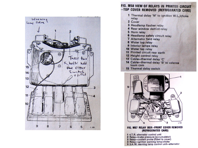 | ||
Bob Reynolds Experienced User Username: bobreynolds Post Number: 45 Registered: 8-2012 |
Thanks for that.  I discovered from another topic that the Thermal Delay Switch is in the Relay Box on the bulkhead. There is more information about it here: http://au.rrforums.net/forum/messages/17001/13508.html?1363114093 | ||
Bob Reynolds Frequent User Username: bobreynolds Post Number: 68 Registered: 8-2012 |
There are 3 units below the large PCB behind the centre of the dash. The left one is the Wash/Wipe unit and the right one is the Intermittent Wipe unit (these are both labelled). The one in the middle is the Auto Park Relay. This is the relay that you can hear clicking when you remove the ingition key. This puts the gearbox into 'Park'. | ||
Bob Reynolds Grand Master Username: bobreynolds Post Number: 375 Registered: 8-2012 |
Just to update this Relay topic: Here is the Starter Relay on my 1975 Shadow. 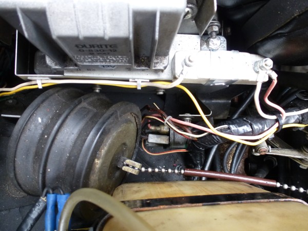 You can see it is connected to the ballast resistor just above it. (Not the original location for the ballast resistor - but a much better one!) And here is the 'Choke-On Start' Relay: 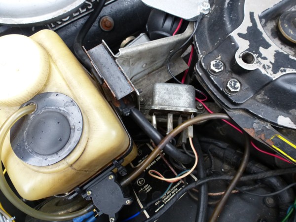 These two relays are connected in parallel and both operate together, so why they weren't placed next to each other I don't know. As a joke I suppose. See above for more information about these relays. Two relays are used because the Starter Solenoid needs 12v to operate it, but the Choke Solenoid needs an Earth. So the Starter relay puts out 12v and the Choke relay puts out an Earth. This could all have been done with a single relay with 2 separate contacts. | ||
Jean-christophe Jost New User Username: jc_jost Post Number: 4 Registered: 3-2016 |
Head lights relay on a 1976 Silver Shadow, right hand drive. This relay is secured outside the relay box, next to the voltage regulator. 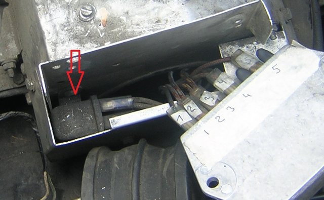 | ||
Geoff Wootton Grand Master Username: dounraey Post Number: 1153 Registered: 5-2012 |
It's amazing how the RR engineers decided to mount relays in the most inaccessible places. In this case however they made it easy for us, by RR standards that is. Just a case of removing the bellows, loosening the four setscrews and pulling the front cover forwards and off. Two of the setscrews are shown in Jean-Christophe's photo, above - the small ones just left of the red arrow. There are two others on the other side of the cover. Whatever you do, do not remove these setscrews - you will never get them back in again. Just loosen them. The cover has slots, rather than holes, so it can be pulled forwards. On my 1974 car, there is no relay in this position. The headlight relay is inside the relay box. The following pic shows the inside of the relay box front cover with a map of the relays. It even gives the French translation for Jean-Christophe. Note however, this is for the 1974 SY1  Geoff | ||
Jean-christophe Jost New User Username: jc_jost Post Number: 5 Registered: 3-2016 |
Thanks Geoff, To continue here is a picture (top and view from undee the board) of the relay box of a 1976 Silver Shadow. According to the wiring colors, it does match your map. The first relays on the left are the water taps. The last one is the horns. 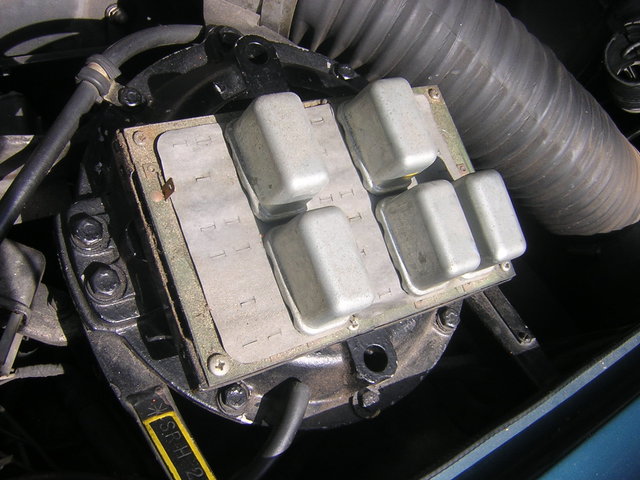 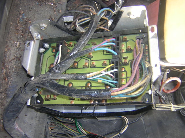 | ||
Robert Noel Reddington Grand Master Username: bob_uk Post Number: 960 Registered: 5-2015 |
Absolutely excellent photos, in both clarity and invaluable information. First class stuff. This is much needed and lots more I say. Bob Reynolds, I told a billion times not to exaggerate, I haven't counted but I would be surprised it there are more than 40. I only use 5 pin relays, �4 or �1 a big handful from the bone yard. My Jeep has ten which live next to the battery in a lidded box. Plus one under dash for electric aerial. Which is about to be removed and a hidden aerial made from 2 metres of insulted copper wire. To bench test a radio, power up between 9vdc and 15vdc and shove any slender metal object up its radio aerial jacksy and stand on one leg whistling I did my way. All un-hidden car aerials are naff. Now where did I put sticky labels. What colour pen do I use? | ||
Bob Reynolds Grand Master Username: bobreynolds Post Number: 383 Registered: 8-2012 |
"Which is about to be removed and a hidden aerial made from 2 metres of insulted copper wire." It will work much better if you don't insult it. | ||
Robert Noel Reddington Grand Master Username: bob_uk Post Number: 965 Registered: 5-2015 |
It's not my fault my stupid spell checker just alters things it has even added numbers to the mix. The dangling wire which simply goes through the bulk head and dangles down by the gear box touching the road. Radio reception is excellent as I thought it would be so the Shadow will be the same. Also for both jeep and Shadow I have made 2 bit of steel with a ball that fits me Garmin Navi. That way no clutter on the dash board. There is also cigar sockets made from 15mm domestic copper water pipe thus tidying up and leaving the RR One free for other use. Simple split the copper pipe. Bend to fit plug. Use shirt button as insulator with a bunch of soldered wire to contact the centre pin. Earth is the copper pipe. Had a smashing day today mucking about in Poole Harbour. This bloke fell in the harbour from a rowing boat. He sort of wobbled and fell in wearing a life jacket. He's fallen in the water. I all wet Mr Mainwaring. Uncle Arther you tell him, my mum won't half be mad. Stupid Boy. On the way back I picked up battery for athe Shadow. Numax brand 069 80 Amp hours CCA 750Amps. �36 inc Vat. Robbing ba****ds 36 quid every body told me Shadows were expensive to run, I wish I had listened that �36 quid means I now have sell my house and I will be homeless. I have 200 children feed. The social only gives me 2000 quid a week. Is they any chance of borrowing fiver, I promise you won't get it back. I stupid neighbour said he doesn't know how I can afford to run a Shadow and a Jeep. The answer easy 3000 miles a year the Jeeps tyres are 10 years old and have 6 mm of tread and a new spare. I don't care about 12 mpg Shadow and 12 mpg Jeep. I put 76 litres in the Jeep it lasts 6 weeks. The neighbour suggested to another neighbor that I was "a drug smuggler my other neighbour told him to keep quiet because I am a bit tasty and have an AK 47 and a 100 rounds. The stupid neighbour actually believes it. | ||
Jean-christophe Jost New User Username: jc_jost Post Number: 6 Registered: 3-2016 |
Hi Me again with more pictures related this time to a seat issue (SRH25085) First picture shows the four electrically operated seats relays. On a 1976 Silver Shadow right hand drive, they sit behind the crash padding on the left of the centre console. They are fitted to a printed circuit. Relays are stamped 33272D. Relay 1 (on the picture) runs the electric engine clockwise (the worm shaft turns clockwise) on the driver side�; Relay 2 anticlockwise. Same rule for relays 3 and 4 on passenger's side. 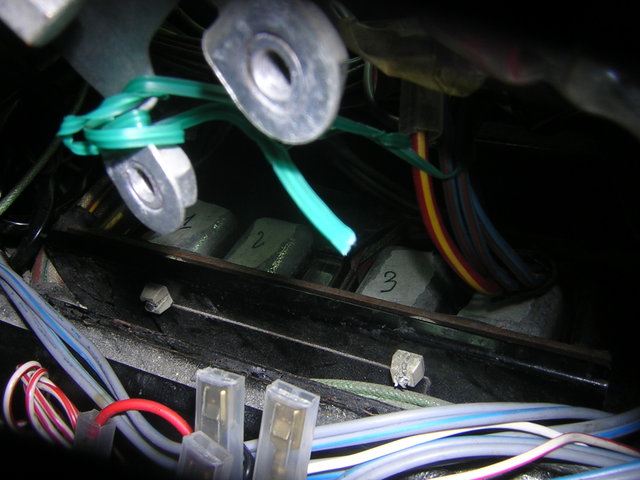 Next picture is the board with all four relays removed. 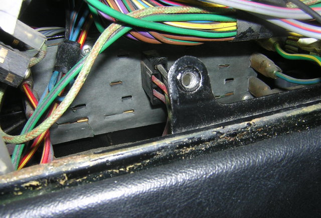 And last picture is the inside of relay 2 (explaining the issue with my front seat..). I would appreciate any comment on this burnt relay. How come�? 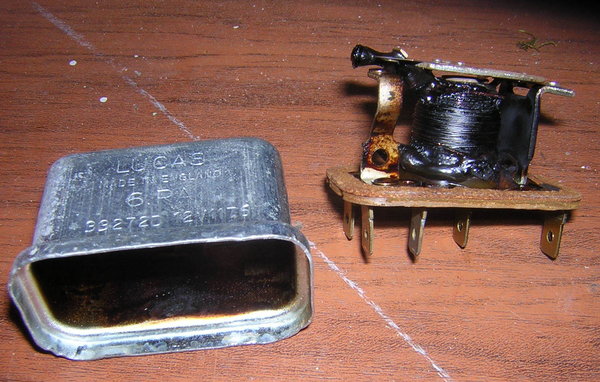 Cheers | ||
Jeff Young Prolific User Username: jeyjey Post Number: 242 Registered: 10-2010 |
Cool! I've never seen one cooked like that. My guess is that overload-type events will produce either a whole bunch of heat and then an open circuit, or a whole bunch of heat and then a short-circuit blowing the fuse. Either way, no more heat. This looks more like a dodgy connection that resulted in higher resistance over the connection, and continual "cooking" of the relay innards. That's one well-blackened case. But I'm not an electrician.... Cheers, Jeff. | ||
Geoff Wootton Grand Master Username: dounraey Post Number: 1163 Registered: 5-2012 |
This is the reason I have fitted a master cutoff switch on my car. I know the risk of fire from a relay is very remote, since it is contained in the protective case, but it does show that any electrical component can fail catastrophically. Note the fuse did not blow to prevent this meltdown. Geoff | ||
Nick Adlam New User Username: crewes_control Post Number: 6 Registered: 12-2015 |
Hear-hear. ALL of our old cars should be fitted with a master cutoff for safety. I always disconnect mine- for that warm fuzzy feeling at night when I'm happy knowing that where there's no power, there's no fire!. | ||
Geoff Wootton Grand Master Username: dounraey Post Number: 1210 Registered: 5-2012 |
Thought I'd add some more information to this valuable thread. On and off I have been trying to resurrect the park off screen function on my windscreen wipers. My car is a 1974 SY1 (SRX18501). It turns out the 3 external relays used in the SY2 cars for the windscreen wipers are not present in the SY1 cars. They are wired differently. However, there is a relay used for the SY1 wipers and I have at last found it. The Crewe Engineers obviously have a great sense of humour. Not only have they have buried it deep beneath the wiring under the top roll, they have hidden it in the wash/wipe control box. Here's how to get at it. Remove the top roll. Just to the middle right of the picture there are the 3 relays and cream coloured coolant level amplifier. The board on which they are mounted has to be removed. 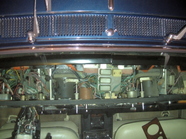 The pic below shows the board removed. The red arrow points to a relay and the two yellow arrows to the wash/wipe and intermittent wipe controllers. These are removed by unbolting the mounting frame. 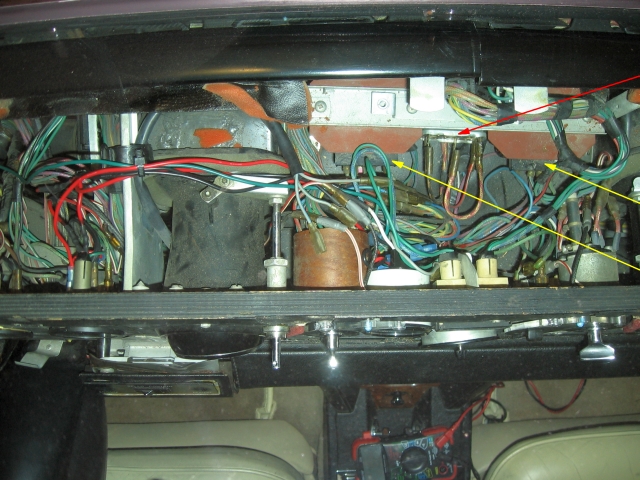 Here is a picture of the wash/wipe controller off the car 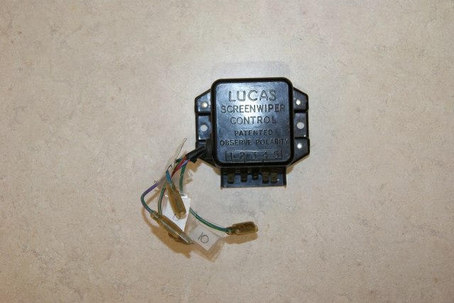 And finally the elusive relay I was searching for. 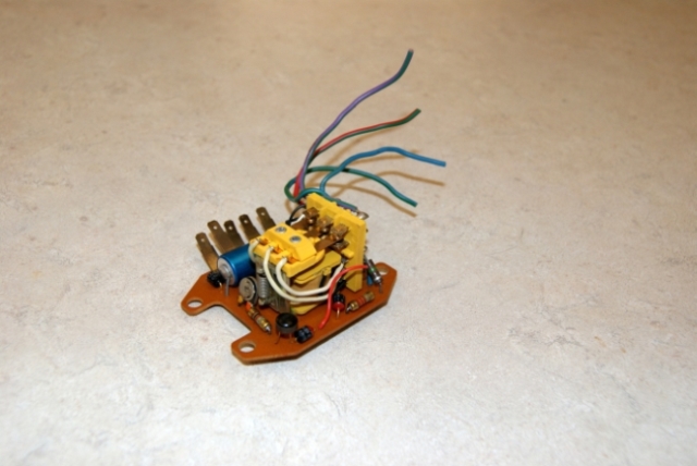 Geoff | ||
richard george yeaman Grand Master Username: richyrich Post Number: 489 Registered: 4-2012 |
Geoff great photos lets us see what is under the top roll. Richard. | ||
Michael Brown Yet to post message Username: michael_j_brrown Post Number: 1 Registered: 2-2018 |
Bob would you happen to know the part number for the Choke-On Start relay? Also, do you know what the "official" name for this relay is for ordering purposes? | ||
Jeff McCarthy Frequent User Username: jefmac2003 Post Number: 679 Registered: 05-2007 |
Reading through 10 years of Crewe Service bulletins (as you do) I came across this diagram for the relay positions on the Shadow Series I. It dates from 1971 I think (forgot to make a note of it when I saved the photo). Anyway it covers most of our cars - the Shadow II diagram is above in this thread. 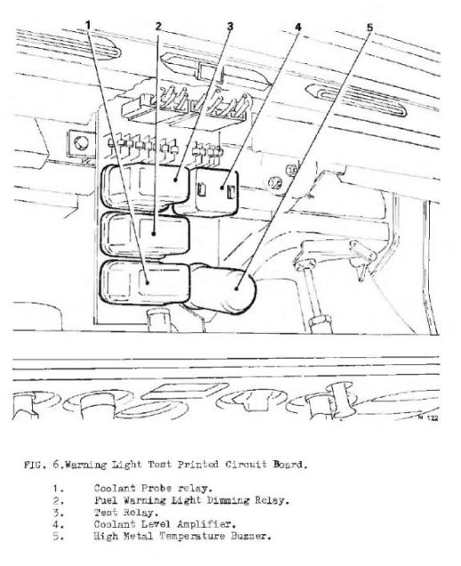 . | ||
Jeff McCarthy Frequent User Username: jefmac2003 Post Number: 680 Registered: 05-2007 |
And here's a diagram from 1972 showing the relays in the boot. 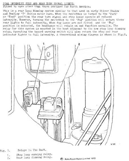 |