| Author | Message | ||
Brian Vogel Frequent User Username: guyslp Post Number: 82 Registered: 6-2009 |
Hello All, When you read the workshop manual on charging the accumulators they describe taking some fairly significant precautions (e.g., doing this in a far corner of the workshop and surrounding the accumulator with a safety shield of sand bags). I am not trying to be glib or flip about charging them, but I want to know what those who do this job actually do in terms of containment, if anything. It seems virtually impossible that these things would/could explode and I have never heard of an actual disaster with one. Does anyone know of a confirmed case of an accumulator charging disaster? In any case, information sharing about how various folks go about doing this part of the job would be valuable to me and, I'm sure, others as well. Brian | ||
David Gore Moderator Username: david_gore Post Number: 1104 Registered: 4-2003 |
Hi Brian, Whilst I agree with your assesssment that catastrophic failure of an accumulator is highly unlikely when recharging; we cannot ignore the fact we are dealing with a pressurised gas in a confined space and the stored energy content can be lethal if released in uncontrolled circumstances especially if the containing vessel ruptures abruptly without prior warning. My exposure to live steam model engineering and boiler codes reminds me that boilers are ALWAYS subjected to a hydrostatic pressure test to 1.5 times the maximum working pressure for a specified period of time before any thought is given to a steam test. The reason for this is the fact that the hydrostatic test is not dangerous as there is no compressed gas involved hence no stored energy and if the boiler fails, the only risk is a thorough soaking depending on which direction the water leak occurs. Linking this to accumulators - it is difficult to hydrostatic test a complete accumulator due to possible damage to the diaphragm thus reducing its working life. It is possible to test the accumulator body without the diaphragm installed however this does not give a 100% guarantee that the subsequently assembled accumulator is safe to recharge in the open without protection from flying shrapnel. My industrial career involved many safety inductions and case studies of injuries and death caused by workers failing to follow designated safe working practices, taking chances instead of verifying correct inspections and safety checks have been undertaken and the most dangerous assumption of all "It won't happen to me......" If the injury is not fatal, the streaker's defence is usually invoked "It seemed a good idea at the time....." Brian, the sticker often placed on factory/mine/quarry washroom mirrors says it all "The person you see is responsible for your safety" and truer words have never been spoken. I would ensure the accumulator is located in a suitable safety cage with adequate padding and sand bags to contain any failure of the accumulator as well as ensuring the charging system components have pressure ratings at least 1.5 times greater than the maximum pressure of the charging gas cylinder. | ||
Hubert Kelly Experienced User Username: h_kelly Post Number: 11 Registered: 3-2012 |
Hi David, just in relation to charging accumulators, do you ever see the day where "once only" charged accumulators might be introduced(for SS1/SS2) ie., rather than recharging an accumulator, One might buy a disposable on?. HK | ||
David Gore Moderator Username: david_gore Post Number: 1105 Registered: 4-2003 |
Hubert - the short answer is no. The size of the market is too small to justify the investment in tooling. A more probable alternative would be a adaptor kit for the Citroen accumulators but this has the problem that the system would have to be converted to mineral oil rather than glycol brake fluid. I doubt if the Citroen diaphragms would be compatible with DOT3/DOT4 + caster oil brake fluid. | ||
Brian Vogel Frequent User Username: guyslp Post Number: 83 Registered: 6-2009 |
David, A bit more info. You are correct that it's well-nigh impossible to believe that Crewe Original parts will ever commission the creation of a "throw away" sealed sphere for the SY series cars. An RROC-US member, however, has already gone the route of using the new sealed accumulator spheres that Citroen makes that are compatible with either LHS (or, in our case, RR363) or LHM. In French they're called multicouche (multi-layer). The two multi-layer spheres that could be used and are closest to the standard RR charge pressure are the Hydractive II sphere with part number 96 181 131 (charge is 75 bar - 1087 PSI) or the XM/Xantia sphere with part number 5276 09 (charge is 70 bar - 1015 PSI). He tried having an adapter created but couldn't successfully get one to fit in the space available. He then had the accumulator control valves rethreaded to accept the new multilayer accumulators directly. I expect that eventually rebuild kits for the spheres will become "made of unobtainium." When that might be, though, is impossible to predict. Brian | ||
Richard Treacy Grand Master Username: richard_treacy Post Number: 2554 Registered: 4-2003 |
The only real issues with the spheres are the pressure and volume of the sphere. CitroŽn LHS spheres will be fine in SY RR363 cars if physically compatible adaptor or not. Likewise CitroŽn LHM spheres in very late coachbuilt SY LHM cars and SZ cars, and that includes SZ gas spring spheres. All are rechargeable. Yes, SZ spheres are rechargeable. Whilst I donít bother as I have no nitrogen cylinders and gauges, most reputable repair shops (at least in Australia) supplement the system pressure test with a sphere nitrogen test and top-up. That applies to SY and SZ alike. They connect the hydrogen cylinder and gauge to the sphere to test the base pressure with the RR363/LHM side depressurised, then simply pump the sphere up to spec while they are at it. It takes just a few minutes to do in-situ. If a sphere is down, say, 20% after a few years, it is a worthwhile exercise to save the sphere. If it is down much more, this is a diagnostic to decide whether or not to replace or overhaul the sphere. Fortunately the spheres are cheap enough not to search for a alternatives. Letís hope that it stays that way. I usually just replace the spheres if in doubt, but have considered the recharge route. The annoyance with recharging DIY is the annual rental fee for the hydrogen cylinders, and if only used every few years it is just a waste. However, the workshops donít ask much cash for a recharge. As to alternative sources of spheres, why bother when Introcar/Flying Spares etc support us all the way at very reasonable prices ? RT. | ||
Brian Vogel Frequent User Username: guyslp Post Number: 84 Registered: 6-2009 |
Richard, I do hope you meant nitrogen, not hydrogen!! (See your next to last paragraph. Yes, I know it's a "write-o" but it's just too good to pass up commenting on.) The conversation regarding alternative sources is in regard to the Shadow series accumulators should the items necessary to rebuild them become "made of unobtainium." However, there are some who would love to be able to use spheres like the ones used on LHM cars, which are essentially disposable, on RR363 cars. I am sure you saw the thread on the RROC-US forums started by the individual to whom I've made reference above. Certainly not the route I'm taking, but information sharing for those who might wish to go that route doesn't hurt anything. Brian | ||
Richard Treacy Grand Master Username: richard_treacy Post Number: 2555 Registered: 4-2003 |
Whoops. I mentioned hydrogen twice. That would blow your mind if it leaked. Seriously, though, I understand that SY diaphragms are identical to those in early CitroŽn ID19s, but I expect that, as usual, the Citi parts are more expensive than the R-R/B ones. Regardless, they are unlikely to be in short supply if spares availability for almost everything for any R-R/B ever made since 1910 is an indication. They are such simple items that I am sure that, in the worst case, anyone could commission a production run themselves were the quantity sufficient. They are just round bits of common-or-garden EPDM with an end-stop washer in the middle. As a yardstick, I have bought SZ spheres for as low as £18 and SY sphere repair kits for as low as £19 when on special offer in recent years. Compare that to the price of just one ball joint, or even to the price of a radiator hose, to keep it all in perspective. A few years back we imported a crate of them from the UK at those prices, and some were fitted to SZs on a Sphere Changing Self Help Day in Victoria. As to the dangers of charging spheres, you donít exactly hover over one while charging it from a standard safety-standars-approved nitrogen cylinder. You would be some metres away with lots of carbody, suspension and wheels to protect you. In any case, they are capable of multiples of the pressure you could possibly apply, and the way they are vibrated and wobbled around on the road must give supreme confidence that charging them gently while sitting comfortably tucked up and under the vehicle is far less stressful for the blighters than barrelling down a bumpy country road. Although I donít recall an incident, to me the moment of truth is winding an SY sphere off its valve body. You then have your head and arms right next to the thing. If the two haves turned on eachother I would run a mile. RT. | ||
David Gore Moderator Username: david_gore Post Number: 1106 Registered: 4-2003 |
Hi Brian, if I were to changeover to the Citroen spheres; I would certainly relocate them to a more accessible location somewhere on the vehicle and fabricate new lines to connect them back into the system. Unfortunately, my years of abstinence from getting up close and personal with the Shadow and derivative cars is making it progressively more difficult to offer constructive comments and advice   . . | ||
Jan Forrest Grand Master Username: got_one Post Number: 348 Registered: 1-2008 |
Although the correct charge is supposed to be pure nitrogen, atmospheric air is (when dried for breathing use) ~80% nitrogen and ~20% oxygen with a few ppm of other gasses. Since I already posess a SCUBA tank and various fittings I recharged my main accumulators 3 years ago with this gas mix with no obvious deleterious effects. Obviously the inclusion of O2 might cause the diaphragms to oxidise a little faster it shouldn't make all that much difference as there will always be some O2 dissolved in the hydraulic fluid to act on the 'wet' side. If this damned rain would let up for a couple of days I might get around to rechecking and, if necessary, recharging them again. The current forecast is for an average month's worth of rain to fall in the next 24 hours! Here in Blighty, apart from an unseasonably warm Easter, we've had the wettest weather since records began smashing all previous records  Ps. Since hydrogen is the smallest of all molecules it would leak through the pores of the diaphragm in very short order. Nothing less than a vitrified surface can prevent this. | ||
Hubert Kelly Experienced User Username: h_kelly Post Number: 14 Registered: 3-2012 |
Hi David, thanks for getting back to me re throw away accumulators. Ill stick with the original for now and renew/exchange as required. I reckon any work on the accumulators, just makes me nervous. Thanks again. Hk | ||
Jan Forrest Grand Master Username: got_one Post Number: 364 Registered: 1-2008 |
As I see it the major threat to life & limb when recharging the accumulators is the relatively small volume. It only takes a second's inattention at the 'wheel' for them to become seriously overcharged. Other than that it certainly isn't 'rocket science', is it? Anyhoo: After a restful long weekend away I'm now fully recharged myself and raring to get stuck into all those niggling little faults that have arisen since I last gave her a fettle a couple of years ago. Wish me luck. | ||
Brian Vogel Frequent User Username: guyslp Post Number: 86 Registered: 6-2009 |
Jan, If you do get around to checking your accumulators for charge after they've been in place for a while please report back. I have no easy access to a pure nitrogen tank to charge mine but have a 3000 PSI paintball tank that has compressed (and dried/purified) air with the necessary regulator, connectors, etc., for charging accumulators. Unless I hear that air depletes *far* faster than straight nitrogen I'm planning to use the setup I have. I can say that I've been unimpressed with nitrogen for inflating tires. It seems to be no better than air as far as "leakage" rate in that application. Brian | ||
David Gore Moderator Username: david_gore Post Number: 1118 Registered: 4-2003 |
Hi Brian, the reason for using Nitrogen rather than air for charging the accumulators might well be to maximise the life of the diaphragms. A lot of elastomers are adversely affected by the presence of Oxygen so the cheapest solution is to use dry Nitrogen. Have never bothered to use Nitrogen in car tyres; my tyres wear out from use long before the rubber starts to degrade!!!! | ||
Brian Vogel Frequent User Username: guyslp Post Number: 87 Registered: 6-2009 |
David, I don't doubt that this would likely be one of the reasons. I have to believe that these diaphragms, just like the seals, would be made of EPDM and the shortest shelf life I've seen reported is 5 - 10 years and, more generally, as "unlimited." EPDM is also highly resistant to oxidation. Given what I've found so far in the ones I've taken apart (or seen taken apart) the diaphragms have appeared to be virtually like new. This is unsurprising given that one side is exposed to what amounts to an inert gas and the other is perpetually awash in fluid. Although I intend to finish the rebuild process on the one remaining accumulator I have that "needs" it, I have become a convert to the idea of recharging and checking that the charge holds rather than rebuilding as the first course of action. Unless the diaphragm somehow ruptures, which seems to me to be very, very unlikely based on how they're constructed and the environment in which they work, it would seem to me to have a service life lasting decades. I believe the accumulators from my '78 Shadow II were never rebuilt, or if rebuilt it was done long, long ago. The diaphragms that came out looked just like the ones that went in, except for the presence of a few tiny raised bits where the thickest part of the diaphragm gets pushed into the top outlet ports on the accumulator when you completely depressurize the system. Brian | ||
Jan Forrest Grand Master Username: got_one Post Number: 366 Registered: 1-2008 |
From memory I believe that the manual states that some accumulators may have a tiny bit of a sharp edge at the bottom which could puncture the diaphragm if all the static nitrogen charge is lost through leakage of the charging valve. As I mentioned when I recharged mine, there was a small rubber sealing washer in the cap rather than the nylon single use ball described in the manual. Obviously I'll get back to you after I've rechecked the pressure in mine, but there's a lot to do before then, so it could be a while ... | ||
Brian Vogel Frequent User Username: guyslp Post Number: 88 Registered: 6-2009 |
Jan, I know there have been reports of ruptured diaphragms and I'd have to believe that your theory is about the only way they could occur. The inside bottom of my accumulator is perfectly smooth and the next thing "down" is the circlip that holds in the ball bearing that acts as the valve. The center of the diaphragm is remarkably thick, probably to withstand being forced against all of the tiny output ports when the system is depressurized. My old ones all had "prints" on them that looked somewhat like the pattern of a multi-hole salt shaker from where they made contact with those ports. I clearly recall that the addition of the rubber o-ring and, particularly, the nylon/plastic/PTFE ball, was in response to leaking from the spheres. I was actually rather shocked when I took mine apart that anyone thought that the initial arrangement would be likely to hold 1000 PSI at all well over time. I have been told that virtually all of these leak to a greater or lesser extent and it's really the nylon ball "squish" seal that does the majority of the work. I will be curious about what you find whenever you next have the chance to check your gas pressures. I'll also post a bit of information I've researched during this quest, as I've got another thread on the RROC-US forums asking about compressed air and recharging accumulators: 1. The amount of oxygen in the compressed air that would be on the "dry side" of the diaphragm is miniscule compared to what is constantly dissolved in the brake fluid (at least in a DOT3 fluid - which RR363 is). Also "clean" compressed air such as is used for SCUBA gear and paintball guns is aridly dry and composed of approximately 78% nitrogen (as is all air). 2. Unless someone can definitively state otherwise, the diaphragms in an RR363 system should be made of EPDM. 3. The shelf-life of EPDM seals is, in most places, stated to be unlimited. (Some say 5-10 years, a few others 10-15 years, but most say unlimited). 4. Oxidation resistance of EPDM is stated to be excellent. 5. Gas permeability of EPDM is stated to be "fair to good." (Which might make one wonder why it was the material of choice, other than the need for compatibility with DOT3 brake fluid). Brian | ||
Jan Forrest Grand Master Username: got_one Post Number: 367 Registered: 1-2008 |
I forgot to mention that having aquired a box of assorted seals and washers I replaced the old ones in the sealing caps with new. Once I've fettled the bits I've scheduled for the next month or two I'll recheck the charge in the accumulators. The only problem is that my charging hose gently leaks a little at those kind of pressures so I have to be quick taking the readings. The last time I recharged them I took the pressure closer to 70 BAR in the knowledge that the small volume of the accumulators would 'lose' the extra 2 BAR while I was disconnecting the charging adaptor. | ||
David Gore Moderator Username: david_gore Post Number: 1120 Registered: 4-2003 |
Brian, another factor I forgot to mention was the effect of ozone on EPDM. Ozone is a very potent oxidising agent and whilst EPDM is more resistant to ozone than other elastomers; it is my understanding stressed EPDM may be more susceptible to ozone degradation; cyclic stressing as encountered in an accumulator may further reduce this resistance. If the air source has high ozone levels, I doubt these will be removed by drying/filtration. Common sources of atmospheric ozone are high UV light levels, electrical arcing from motors with commutators, other forms of electrical discharges and interaction between sunlight, hydrocarbons and nitrogen oxides. As far as oxygen dissolved in brake fluid is concerned, the current acceptable service life of diaphragms suggests this has little or no effect on the life of the diaphragms. I suggest this is because the oxygen is not in gaseous form and the concentrations are less than that needed to degrade the EPDM. | ||
Hubert Kelly Frequent User Username: h_kelly Post Number: 54 Registered: 3-2012 |
Hi, I came across this video today, thought it might benefit someone contemplating the recondition of accumulators (its of a Citroen DS) http://www.youtube.com/watch?v=AEUTyzbC1Wo&feature=endscreen&NR=1 hk | ||
Brian Vogel Prolific User Username: guyslp Post Number: 118 Registered: 6-2009 |
Hubert, Interesting video, both in regard to the similarities and the differences between the Citroen and RR versions of the accumulators. The biggest difference on the "taking it apart" side of the equation is that the Citroen accumulator is composed of two halves that screw together while the RR accumulator is three parts: two halves of the sphere (lower half with threads) and a ring that spins on to hold the halves together. I don't know whether the accumulators for the "one series" cars would allow you to put them into a jig like he used and then spin the ring off, but the ones from the two series cars almost certainly wouldn't (I've just finished rebuilding a set of these). The "diaphragm grip" that they show is definitely a real phenomenon. That's one advantage of the RR variant, if you're using the "official method" of getting the ring off, you don't spin either half of the accumulator against the diaphragm but instead spin the ring off the two halves, each of which is held immobile by the hex on the respective ends. I notice the new Citroen diaphragm has a metal "protector patch" in the center, which is different from the ones from Crewe. I would not use vaseline as they did since this diaphragm is EPDM (if we're talking about an LHS/RR363 car) and EPDM does not like petroleum products. Smearing those edges with a bit of actual brake fluid works just fine. The most important thing they noted is the use of anti-seize compound on the threads upon reassembly. I cannot tell you how much easier this job would have been for me to do had the threads been treated in this way by the last person who did this job ahead of me. Brian | ||
Geoff Unregistered guest Posted From: 68.104.65.17 |
I reconditioned the accumulators on my series 1 1974 Silver Shadow a couple of month's ago and can confirm Brians point that the series 1 sphere would probably not fit the jig shown in the youtube video. It could be inserted, but the ring would prevent it going in far enough for the setscrews to be tightened on to the rim. However, since I was having such problems separating the spheres on my car I made a low cost variant of the jig shown in the video. I bought an offcut of 3/8" mild steel plate from a local stockholders, 18" x 6". I cut a 4" hole in the plate, filed it as perfectly round as I could and then cut a 1/4" slot from the hole to one end of the plate. I then bolted it to my workbench, inserted the lower hemisphere into the hole and clamped it up with a G clamp, which was also bolted in place. This held the accumulator really firm and allowed me to undo the ring. The sphere was seriously tight and to have attempted to separate it in the prescribed RR method of holding the hex nut in a vice would have damaged it. It would have just been torn out of the vice - the ring was that tight. I include this as it might help inject some fresh ideas for anyone having trouble separating their spheres - a notoriously difficult job. Geoff (Message approved by david_gore) | ||
Omar M. Shams Prolific User Username: omar Post Number: 293 Registered: 4-2009 |
Dear Geoff, You will save us all a great deal of future agro with your suggested cllamping procedure. Are you able to show us any pictures or a sketch or a drawing to eliminate ambiguity? Many years ago I had to cut the screwed ring off one accumulator to separate the two halves. I dont ever want to do that again. Thanks Omar | ||
Brian Vogel Prolific User Username: guyslp Post Number: 125 Registered: 6-2009 |
Just for the record my setup used a homemade set of sockets that were held on by bar stock welded to metal plates. I drilled multiple holes in the metal plates and mounted them to a wooden vice. The top hex is 1-11/16" (if memory serves, I'll correct later), which required 3/4" bar stock to hold the socket, and the bottom is 15/16" and required 1/2" bar stock. One of my accumulator rings was "welded" on and the trick that finally worked to allow it to be removed by the pin wrench was giving the ring a number of hard knocks around its circumference with a 3-lb hammer while the accumulator was resting on a concrete floor. I had a pin wrench custom made with a 3-foot handle such that this could be a 1-man job. It allows me to slip on an additional pipe for more leverage, and I needed to do so in order to get that ring off. All I can tell anyone is that if you are a merciful person you will not even consider putting the ring back on without using anti-seize compound on the threads. I often wonder how much work and misery might have been avoided with getting these things apart after years and years had this stuff been in existence "way back when." [And, of course, individuals using it as well.] If anyone would like to see photos of the setup I used I would be happy to e-mail them. I just tried attaching them and had forgotten that this forum not only enforces a 640x480 pixel maximum but also won't allow 480x640. I don't want to resize and crop six photos at the moment. Brian, who uses anti-seize on virtually every threaded item I come in contact with these days, down to the nuts & posts on the fan shroud | ||
Omar M. Shams Prolific User Username: omar Post Number: 294 Registered: 4-2009 |
Yes please Brian. Photos will be most welcome. Please send me a PM. Thanks Omar | ||
Geoff Unregistered guest Posted From: 68.104.65.17 |
Omar, I did indeed try to upload a photograph of my homemade clamp but as a guest user I could not resize it down to the 1kb limit. If anyone reads this in future I would be very happy to send photos of the clamp and also the pin wrench I fabricated. I warn now that these are not the most beautiful pieces of engineering you will ever see, and thats putting it mildly, however they were low cost and very effective. I am pleased to read that even such an expert restorer as Brian has to resort to using a hammer on occassions. The truth is the ring of the accumulator essentially becomes welded to the hemispheres and has to be shocked free. In my case I have a two handled pin wrench and was able to separate the first accumulator quite easily however the second would not budge. The process culminated in the use of two 8 foot extension bars with the pin wrench clamped in place and still the ring would not come free. The judicious use of a lump hammer to the side of the pin wrench finally resolved the issue - 5 sharp blows and the ring finally turned, to scenes of great jubilation. In my view, given the force required to separate a really stubborn accumulator it is not sufficient to simply hold the hex net on the lower hemisphere in a vice. It would just be torn out and would burr the edges of the hex nut. This part of the accumulator adjoins a machined face that screws into the valve body, so it is essential that this is not damaged in any way. Needless to say, I took Brians advice from a previous posting and used plenty of anti-seize compound when reassembling the accumulators. Geoff Wootton Las Vegas, US (Message approved by david_gore) | ||
David Gore Moderator Username: david_gore Post Number: 1148 Registered: 4-2003 |
Geoff, guest users cannot download images or files to this forum. Please register as a user and you can post your photos - the best size to avoid scrolling problems is 640 x 480 or 480 x 640 pixels. This gives a good size screen image and resolution. Brian, please post your photos sideways if necessary and I will rotate them like I did recently for another member. Otherwise email them to me and I will process and post them for you - you should still have my email address. | ||
Michael Hicks Frequent User Username: bentleyman22 Post Number: 84 Registered: 12-2011 |
http://www.flickr.com/photos/11834890@N06/1889712997/in/photostream | ||
Brian Vogel Prolific User Username: guyslp Post Number: 126 Registered: 6-2009 |
OK, there's enough interest in the photos that I decided to resize them while eating my dinner and posting them here. All are either 640x425 or 425x640. We'll see if they all post. I've had this forum complain at me before if the horizontal and vertical dimensions are reversed. Note: I just got an error message reading, "Your uploaded image exceeded the maximum dimensions of 640 x 480. Please shrink your image to be smaller than these dimensions.," for the three pin wrench after attached images. All I did was rotate them to switch all three to be 640x425 pixels. If there is anyone reading who has any ability to fix this, please do. I get wanting to keep image sizes down, but a 640x425 image and a 425x640 image with the same content are identical in size. It's maddening to have to care which dimension is which!! 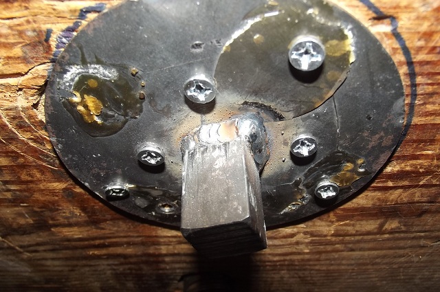 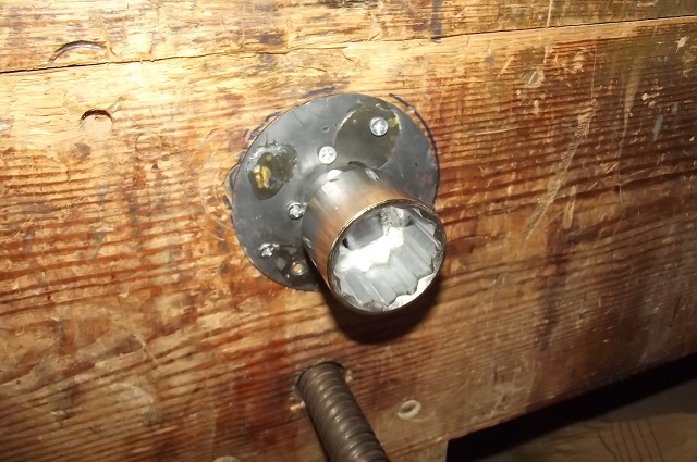 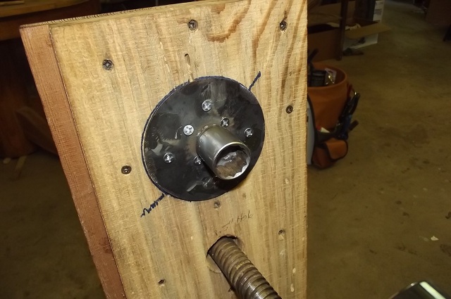 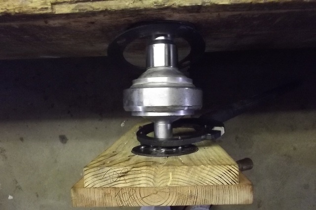 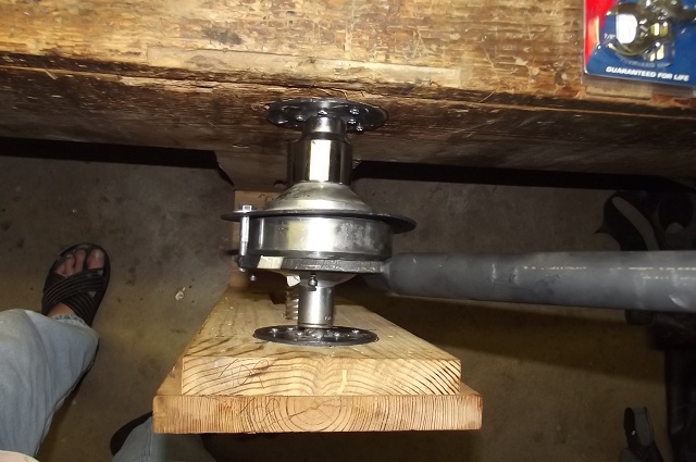 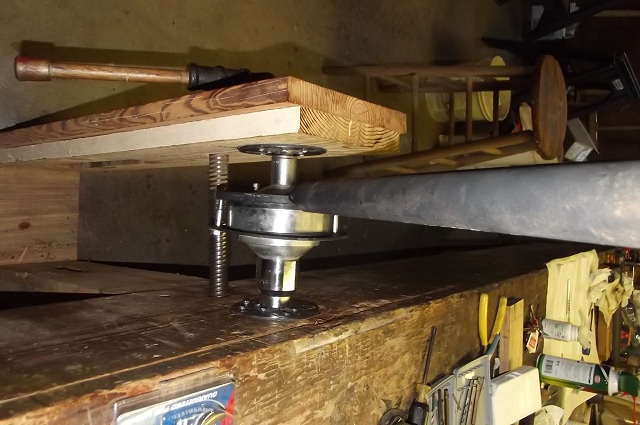 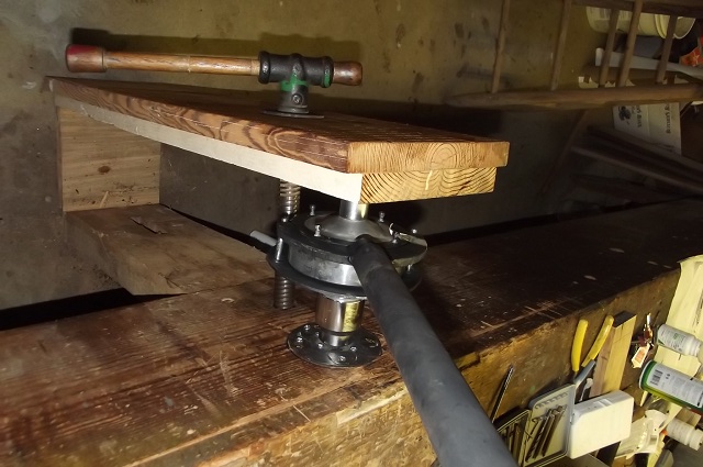 I had no difficulty with damage to the hex fittings using this setup (there is damage to the top hex from someone who tried using a jig that held the ring and tried to spin the top with an impact wrench. Even after that this setup worked). I did have issues with finding out the necessary number and "thickness" of screws to hold the mounts in place on the workbench and the vice. The only thing I'd change is I'd go with fewer screws that had a significantly greater diameter rather than adding more and more with a smaller diameter, particularly on the workbench side that held the large hex socket setup in place. Brian | ||
Geoff Wootton Yet to post message Username: dounraey Post Number: 1 Registered: 5-2012 |
Here's my effort. 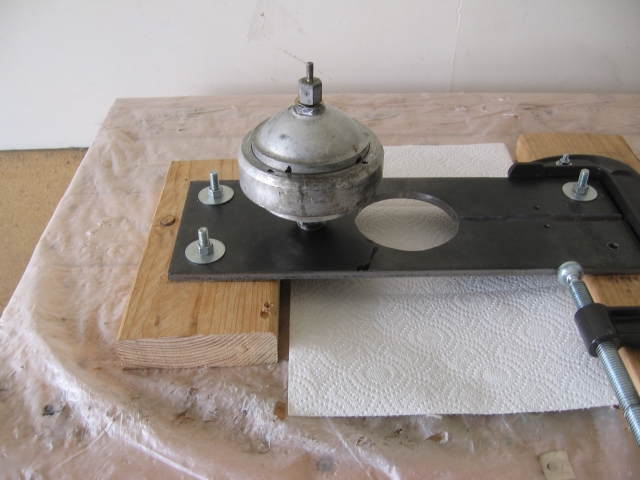 This photo shows the accumulator clamped in position. The G clamp is held in place by two bolts - one of them is out of shot. 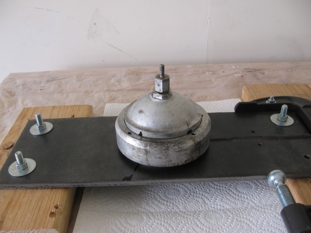 I have just been checking out Brian's photos and note that he wears the same heavy duty protective footwear as I do. | ||
Omar M. Shams Prolific User Username: omar Post Number: 295 Registered: 4-2009 |
brilliant!!! | ||
Brian Vogel Prolific User Username: guyslp Post Number: 127 Registered: 6-2009 |
Geoff, Since my feet are nowhere near these "toe crushers" when actually applying force to 'em, that's all the protection I need in mid-summer in Virginia. I do, however, have heavy-duty steel-toed boots when the occasion calls for them (which is very, very rare)! Brian | ||
Geoff Wootton New User Username: dounraey Post Number: 2 Registered: 5-2012 |
Brian, I was only joking. I too am very safety conscious, particularly when jacking up the car. We have similar summer temperatures here in Vegas - 100F most days and the local housing association insist on your keeping the garage doors closed when working on cars - gets quite hot in there. Geoff | ||
Brian Vogel Prolific User Username: guyslp Post Number: 128 Registered: 6-2009 |
Geoff, Believe me, I got your drift. It's the smartass in me that dictated my reply. I really cannot imagine working in a closed, non-climate-controlled garage in or near Vegas in the summer!! I couldn't do it, that's for sure. Brian, who keeps hoping that his "in garage" experience won't span the next season, but . . . | ||
Hubert Kelly Frequent User Username: h_kelly Post Number: 60 Registered: 3-2012 |
Thanks Geoff and Brian your photo's are priceless, they have spoken a thousand words. hk | ||
David Gore Moderator Username: david_gore Post Number: 1149 Registered: 4-2003 |
Brian and Geoff - congratulations and thanks for posting very useful and relevant information that will benefit those of us who have to service their accumulators in future. The images are worth an infinite number of words IMHO. | ||
Geoff Wootton New User Username: dounraey Post Number: 3 Registered: 5-2012 |
For the purposes of completeness I would like to include this final photograph of my homemade pin wrench. You will see it is designed for two person operation and compliments the design of the accumulator clamp. 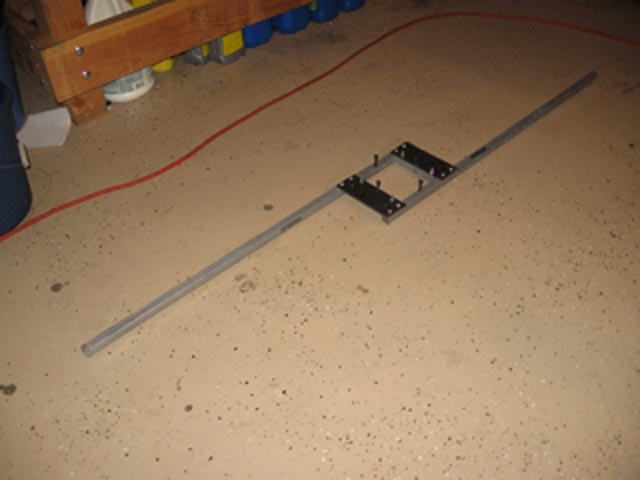 The pin wrench is fabricated from three pry bars purchased from a low cost tool store. These are made of toughened steel. Since I do not own a welder I opted to bolt the structure together. Welding would have made for a much simpler and neater job. There are four 10/32 setscrews that can be adjusted down into the pin holes on the accumulator ring. | ||
Geoff Wootton New User Username: dounraey Post Number: 4 Registered: 5-2012 |
I did of course mean complements and not compliments in my previous entry - ouch | ||
David Gore Moderator Username: david_gore Post Number: 1150 Registered: 4-2003 |
Geoff, you got it right the first time.....   . . | ||
Jeff Young Frequent User Username: jeyjey Post Number: 97 Registered: 10-2010 |
Brilliant pictures, guys. Thanks for posting! Brian, am I correct in surmising that the second ring on your pin wrench is just to keep it aligned (and the pins in the holes)? Thanks, Jeff. | ||
Brian Vogel Prolific User Username: guyslp Post Number: 129 Registered: 6-2009 |
Jeff, Yes, the ring on the side with the handle is the "hard working ring" that has the pins made of hex cap screws of hardened steel, which allows for "easy" replacement if one breaks. I say "easy" because the threads on the exposed part of the screws gets very, very beat up due to the forces on them. I haven't had any break, but have played with removing them just to see what it would entail. It's a miracle that this system works at all with the extremely shallow depth of the holes for the pins in the sphere ring. The other side is nothing more than a fairly thin steel ring that is bolted down against the opposing side of the sphere ring to keep the working half firmly in place. I had the wrench built for me by a local welder and it has a heavy pipe handle approximately 3 feet long. You can (and I did) easily add an additional extension pipe if you need more torque. One additional note is that one generally cannot get the sphere rings to budge using a constant force. I could only get them to break free when applying shock force by hitting the end of the handle (or extension) with a 3-lb hammer until the ring began to budge. Once there was even the slightest movement one could grab the handle and with a good application of body weight easily get the thing to come off. I've also got additional photos of the wrench if anyone wants to see detail shots regarding its construction. Brian | ||
Hubert Kelly Frequent User Username: h_kelly Post Number: 69 Registered: 3-2012 |
Hi All, Flying Spares now sell a "throw away" accumulator for the Shadow 1/2 series... its twice the price though. (personally... I am delighted, as I now have the choice to buy a new, or restore the old accumulator ). Given the choice Ill buy the new. hk | ||
richard george yeaman Frequent User Username: richyrich Post Number: 82 Registered: 4-2012 |
Hubert. I think that would be my choice also given the amount of special equipment needed and then finding someone to recharge them, How long would new ones last before they would need replaced again. Cheers. | ||
Hubert Kelly Frequent User Username: h_kelly Post Number: 70 Registered: 3-2012 |
Richard, In the long run it will probably be much cheaper as one can do a D.I.Y. job thus saving on mechanic bills?. ps hope the snow has cleared. HK | ||
Geoff Wootton Prolific User Username: dounraey Post Number: 144 Registered: 5-2012 |
Great news for people in the UK. However, for those in the US, Australia and other countries the exchange rate and postal charges more than double the price. Also, it is technically illegal to send these units by air, for obvious reasons, although I believe FS has never had a problem in this regard. At least with the disposable units there is not the additional postal charge of returning the original unit. If I lived in the UK I would always go for the exhange or disposable unit rather than recondition my existing accummulators, however the postal/exchange rate costs makes the very painful reconditioning route much more attractive. | ||
Brian Vogel Grand Master Username: guyslp Post Number: 592 Registered: 6-2009 |
Hubert Kelly wrote: Flying Spares now sell a "throw away" accumulator for the Shadow 1/2 series... it's twice the price though. (personally... I am delighted, as I now have the choice to buy a new, or restore the old accumulator ). Given the choice I'll buy the new. Hubert, just curious if you (or any reader, for that matter) has decided to give the RH2390P "Disposable" Accumulator a try? The topic has come up elsewhere, and I have yet to hear anything from anyone who's actually using these. I presume they're the new (or at least "newish") CitroŽn accumulators that have the membrane that's compatible with either RR363 or HSMO with the necessary changes to the threading. I've often wondered if these would hold their charges longer than is typical for the conventional accumulators. Brian |