| Author | Message | ||
Jeffrey McCarthy Prolific User Username: jefmac2003 Post Number: 254 Registered: 5-2007 |
I have disconnected the cruise control switch on SRH20280 and installed a Spirit Cruise control switch on the gear-change lever. The 4 wires from the new switch are Red, Brown, Blue and Green Plastic; these colours do not appear on the Spirit Cruise Control Wiring diagram where the switch indicates bi-coloured plastic wires. The Shadow wires are Purple/Blue Cotton, Purple/Brown cotton and Purple/Red plastic (and presumably a black earth wire on the on/off switch). On the switch side there are purple/blue (x 2; one to each momo switch)) on one connector purple/red ( x 2 as above) on another and a purple/red cotton connected to the engage switch. There also an extra connection to the on/off switch from the engage switch - it is purple brown) The switches seem to have the same functions - a permanent on/off switch and 2 momentary switches for the Set & Resume functions. The aim is (obviously) to use the Spirit switch to run the Shadow speedostat. Now I'm assuming things wont be so simple as just connecting the wires - I'm assuming at least a relay or two. I've read all I can in the library and Tee Two and cant see anything that indicates that this can't be done Any advice - even if it's just the name of an autoelectrician who's familiar with both sysytems - would be much appreciated. Some photos... 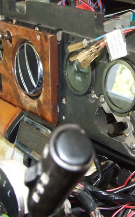 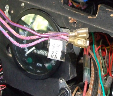  (Message edited by jefmac2003 on 13 February 2011) (Message edited by david_gore on 14 February 2011) | ||
Jeffrey McCarthy Prolific User Username: jefmac2003 Post Number: 255 Registered: 5-2007 |
Just a correction to the above. The Shadow CC unit has a blue/green plastic wire connected to the on/off switch (not an earth). This is connected to the Reverse Lamps Switch. Does anyone happen to know where this switch is physically located in the loom? Apart from the above wire it has a white/brown plastic & a green/yellow plastic wire connected to it. This is a long term work in progress so I'll report back from time to time as I experiment. Incidentally the point of doing this is twofold: I found the cruise control painfully distracting to use in its original position so I didn't. Also I'm installing a hidden GPS mount in a Corniche ashtray which fits exactly into the space. The GPS antenna is hidden also (under the fibreglass dash) so there will be no indication of a GPS or wiring to distract from the original 'look'. The position is perfect from a vision safety point of view - the GPS screen is easily seen through the steering wheel at Speedometer height. It's all easily reversible and no original parts were harmed in the making of this modification. (Message edited by jefmac2003 on 14 February 2011) | ||
Chris Browne Experienced User Username: chrisb Post Number: 37 Registered: 2-2010 |
Hi Jeff, Just read your posts. You do like a challenge, don't you! I may be wrong here but why would there be a connection to the reversing light switch - I don't see the need for that - what would its function be? Isn't it more likely to be a connection to the brake light switch, as on the Shadow 2, which switches off the cruise control as soon as the brakes are applied and the lights come on? Just a thought. Kind regards, Chris | ||
John Kilkenny Prolific User Username: john_kilkenny Post Number: 113 Registered: 6-2005 |
Jeffrey, The blue/green plastic wire provides +12V to the Speed Control Unit. This comes from Fuse 11 via the Height Control Solenoid Switch and the Reverse Lamps Switch. It will be at +12v when the Reverse Lamp Switch is OFF (i.e. not in reverse gear) and the Height Control Solenoid is NOT energised (i.e. not fast levelling, which effectively means not in neutral gear) The white/brown wire goes to the Reversing Lamps and the green/yellow wire goes to the Height Control Solenoid Switch. John | ||
Chris Browne Experienced User Username: chrisb Post Number: 38 Registered: 2-2010 |
Hi John and Jeff, OOPS! Clearly my last post completely wrong. Kind regards, Chris | ||
Jeffrey McCarthy Prolific User Username: jefmac2003 Post Number: 256 Registered: 5-2007 |
Yes, it confused me for a while Chris but I thought it must be something along the lines John describes. It only works if you're in drive and going at least 48kph. Here is a snapshot of the wiring diagram for the switch on the Spirit. 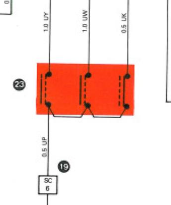 And here is a snapshot of the Switch panel on the Shadow. 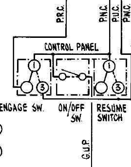 The problem is twofold: 1- Most importantly - are the 2 switches configured in the same way? They both consist of an on/off switch and 2 momentary switches. However the Shadow panel has various wires cross connected to the 2 microswitches. It is not at all clear to me from the diagrams that this is replicated internally on the Spirit switch. 2- The four wires exiting from the Spirit switch are Red, Brown, Blue and Green solid colour plastic coated. These lead to a plug where presumably the colours mentioned on the diagram are followed. Which, however, corresponds to which? Two of them must be the on/off switch and the other 2 must be 'Set' and 'Resume'. The second 2 will be easy to figure out in practice (There's a nice 5 kilometer straight bit of back road nearby) - if they are wired backwards then set and resume will function as each other. I'll try various combinations starting with the red wire attached to the Shadows Blue/green plastic wire and the brown attached to purple/brown cotton. This won't happen for a week or two though - I'm busy stripping dye from the leather and varnish from the woodwork. |