| Author | Message | ||
John Kilkenny Prolific User Username: john_kilkenny Post Number: 106 Registered: 6-2005 |
I recently needed to repair the sump oil level transmitter on SRH1405. The symptom was the gauge needle going past full scale when the Warning Lamp Test Switch was pressed, giving a false indication of a full sump. The cause was an open circuit oil level transmitter line, in this case a faulty solder joint at the end of the wire wound resistor in the transmitter. To help me understand the circuit operation I prepared the following article and circuit diagram which may be of interest to forum members. Circuit Description The fuel and oil level transmitters each contain a wire wound resistor with a float operated sliding contact. The resistance seen at the gauge output terminal (T) increases as the float rises with the fuel or oil level. The fuel level transmitter is accessible at the top of the fuel tank in the boot and the oil level transmitter is located on the driver�s side (RH Drive car) of the sump. The operation of the gauge itself is based on two opposing coils, each with a resistor in parallel. One resistor is fixed; the other is variable and can be either the fuel transmitter resistor or the oil transmitter resistor. One coil receives a fixed current while the current through the other coil depends on the value of the resistor across it, the lower the resistor the less current through the coil. The ratio of the currents through the two coils decides the position of the gauge needle. The fuel tank transmitter also contains a switch which operates when the amount of fuel drops below about 12 litres. This switch operates the green Low Fuel Lamp in the Warning Lamp Panel. A dimming relay reduces the intensity of this lamp when the car lights are on. 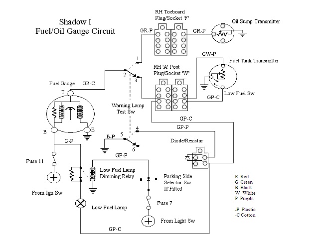 A useful check of the oil level transmitter can be done during an oil change. After adding five litres of the new oil switch on the ignition and press the Warning Lamp Test Switch. The gauge needle should indicate a less than full sump. Add the rest of the oil and a full sump should be indicated when the Test Switch is operated. The owner�s manual emphasizes that the oil level indicator should only be used as a quick check on a journey, the dipstick must be used when topping up. | ||
Jan Forrest Prolific User Username: got_one Post Number: 179 Registered: 1-2008 |
I've always preferred to use the dipstick - only pressing the dash button occasionally for amusement. | ||
Geoff Wootton Grand Master Username: dounraey Post Number: 1957 Registered: 5-2012 |
Thanks for publishing this John. I have just drained the oil and fitted a new filter but before I fill the engine with oil thought I'd take a look at the faulty oil level sender unit. When the dashboard button is pressed the fuel/oil gauge deflects to maximum. I'm thinking of following Bill Coburn's advice in tee-one topics and removing and cleaning the sender, whilst the sump is empty of oil. Before doing so I would welcome any advice on tests I could carry out before going ahead with this. It occurs to me that since the needle deflects to maximum it is likely to be an electrical fault, unless of course the sender unit has seized in it's maximum position. | ||
John Kilkenny Prolific User Username: john_kilkenny Post Number: 282 Registered: 6-2005 |
Geoff, If the petrol gauge is still OK the fault is probably an open circuit in the oil level transmitter. Check this by connecting the output to earth. This should give a level of zero. If still maximum the open circuit is further back. The transmitter is easily removed but be careful not to bend the float wire. Also when refitting do not overtighten the mounting screws. The cover is diecast and is easily bent. Good luck, John | ||
Geoff Wootton Grand Master Username: dounraey Post Number: 1958 Registered: 5-2012 |
John Thanks for the details of the test (connect to earth). I had recalled there was such a check but could not find it despite extensive searching of the forum. Now I know. One thing I have found is the small rubber boot on top of the unit, which I presume covers a 2ba connector nut, has over the years become as hard as bakelite. I will probably snip the wire and remove the unit rather than risk damaging the connector beneath. Tomorrow will be interesting. Thanks again for your help. Geoff | ||
Geoff Wootton Grand Master Username: dounraey Post Number: 1959 Registered: 5-2012 |
I've removed the oil level sender unit and on removing the front plate found, to my surprise, it was full of oil. On considering this I am wondering if that's how it's meant to be. Oil is a good electrical insulator so maybe it's ok. Does anyone know? The only place the oil could get in is through the bearing where the float arm enters the unit. I have arrowed it in the lower photo. Should there be a seal here? As always, any advice will be greatly appreciated. 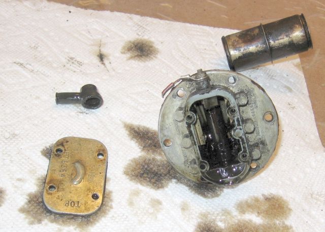 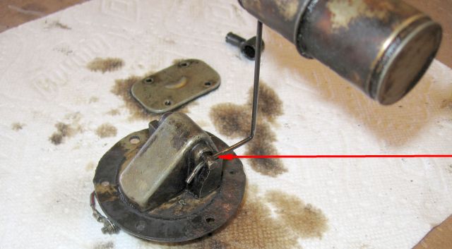 | ||
Patrick Lockyer. Grand Master Username: pat_lockyer Post Number: 1887 Registered: 9-2004 |
Geoff, repaired mine many years ago, from memory the inside was oil free. Have looked on some old postings but have not found any pixs or the write up. The windings were ok but the contact arm was an open circuit causing the failing on my SS1. | ||
John Kilkenny Prolific User Username: john_kilkenny Post Number: 284 Registered: 6-2005 |
Geoff, I wouldn't worry about oil getting in. Firstly confirm the problem is an open circuit between the terminal and the transmitter body. From memory the resistance should vary between about 80 ohms and much lower as the arm swings. The weak points are the solder joints with the fine coil wire. | ||
Geoff Wootton Grand Master Username: dounraey Post Number: 1960 Registered: 5-2012 |
Patrick - looks like mine is open circuit. John - You were right about the weak solder joint. The solder to the earth joint has come completely free. However, a bigger problem is there appears to be a break in the winding. I will do some further checks tomorrow and if all fails may consider trying to extract the winding and seeing if I can repair it. Failing that it will be a purchase from Flying Spares. The first photo below is to show the context and the second a close up of the loose solder joint and what appears to be a break in the winding, just below the slider, just to the right of the centre of the photo. 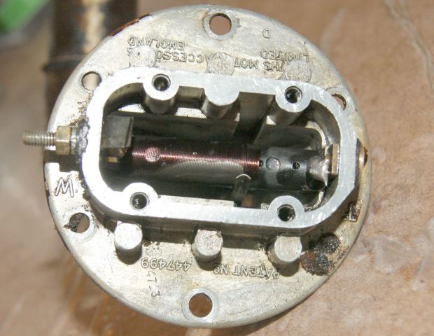 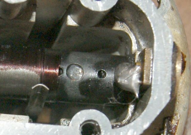 | ||
Jim Walters Prolific User Username: jim_walters Post Number: 162 Registered: 1-2014 |
Geoff, there is no reason you can't use a repro fuel gauge sender for this application. This one for an MGA from Moss Motors should work just fine: https://mossmotors.com/sending-unit-fuel-gauge-2?assoc=16533 You will likely have to shorten the rod but otherwise it will work and save you a considerable sum. SRH8505 SRC18015 SRE22493 NAC-05370 www.bristolmotors.com | ||
Jim Walters Prolific User Username: jim_walters Post Number: 163 Registered: 1-2014 |
Also this info on the sender is useful to know: https://mossmotors.com/media/instructions/980-004.pdf SRH8505 SRC18015 SRE22493 NAC-05370 www.bristolmotors.com | ||
Geoff Wootton Grand Master Username: dounraey Post Number: 1961 Registered: 5-2012 |
Jim Many thanks for the link to the sender unit and the associated information sheet. I have ordered one. Here's the latest episode in the story: This morning I clamped the loose solder connection to earth with a crocodile clip and measured the resistance. I got 79 ohms, which is what John specified it should be. As I moved the slider the resistance reduced as expected however at 68 ohms the sender unit went open circuit. I tried to get a lower reading by applying gentle finger pressure against the slider but just could not get any further readings. I also noticed there is no physical resistance when moving the float up and down so I suspect that even if I could get the unit to work, the weakness in the slider would lead to constant intermittent open circuits. I think I have to accept the unit is beyond easy repair and so have ordered the low price sender unit that Jim has pointed to. I will send an update when I have received the new sender unit detailing what mods are required to get it to fit, in case any other owners need to carry out the same repair on their car. Geoff | ||
John Kilkenny Prolific User Username: john_kilkenny Post Number: 285 Registered: 6-2005 |
Geoff, If the slider is not making contact you will measure the resistance at 80 ohms, not an open circuit so you may need to investigate further. You will not feel any physical resistance when moving the float because of the lever effect of the arm. Also if you replace the unit you need to check that the new one has a 80 ohm coil ; if not the gauge will be inaccurate. John | ||
Geoff Wootton Grand Master Username: dounraey Post Number: 1962 Registered: 5-2012 |
John Of course, I'm not thinking this out correctly. If the slider comes away then you are just measuring the resistance through the coil, as you said. The unit is definitely going open circuit when I move the slider down through 68 ohms. I have repeated this and it happens every time. I can only think the winding is broken at this point. As the slider moves down the coil it pulls the wires apart and when the slider is moved back up again, it pushes the wires together. I cannot think of any other reason why I would get open circuit at this point each time. I will carry out a close examination under magnification tomorrow. If I see a break I'm wondering if a small dab of solder might work, carefully sanded down to make the coil smooth for the slider. when the new unit arrives I will check the resistance for 80 ohms. Geoff | ||
Alan Dibley Prolific User Username: alsdibley Post Number: 148 Registered: 10-2009 |
Geoff, the wire used in the coil is almost certainly un-solderable (is that a word?), being a chrome alloy or similar. Prepare for frustration. Alan D. | ||
David Gore Moderator Username: david_gore Post Number: 2910 Registered: 4-2003 |
Alan, you are correct. The wire is most likely a Nickel-Chromium alloy which has good heat/corrosion/oxidation resistance properties which makes them extremely difficult to solder as the solder cannot "wick" the alloy surface to make a good connection between adjacent surfaces. | ||
Christian S. Hansen Grand Master Username: enquiring_mind Post Number: 803 Registered: 4-2015 |
Geoff...We all await with baited breath the results of how close to "plug & play" it is. Certainly looks darn close and at about $60US for the Moss Motors version (Thanks Jim!) there is no merit other than curiosity to the repair of the old sender...but you knew that! Just saying! . | ||
Geoff Wootton Grand Master Username: dounraey Post Number: 1964 Registered: 5-2012 |
Alan and David - thanks for that info - I will not attempt to solder - you've probably just saved me an hour of frustration trying to do the impossible. Christian - USPS tracking tells me the unit will arrive tomorrow (Thu 7th). I will report back on the weekend when I have hopefully fitted it. One problem I can already foresee (from the photo) is the new unit comes with a plastic float. I'm hoping the clip is the same size so I can clip on the original brass float. Failing that I'm wondering if a plastic float would be ok in a cauldron of swirling hot oil. | ||
Omar M. Shams Grand Master Username: omar Post Number: 1544 Registered: 4-2009 |
Oh wow Jim!!! what a fantastic find!!! I wonder if Brian has this item on his list of alternative parts? | ||
John Kilkenny Prolific User Username: john_kilkenny Post Number: 286 Registered: 6-2005 |
Geoff, This is indeed a strange fault. It would be unusual for the wire to break and re-join in such a way. The wire is very fine and the resistance is due more to its length rather than its composition. The wire is solderable which is how it is attached at both ends. John | ||
David Gore Moderator Username: david_gore Post Number: 2913 Registered: 4-2003 |
John, The actual situation is the fact that the overall resistance value is determined by both the inherent resistance of the wire alloy AND its length; the longer the wire, the greater the resistance. The thinner the wire, the more compact is the resistor but the lower the amperage that can safely be passed through the resistor without overheating. The thicker the wire, the more current that can be passed but at the expense of greater heat generation. Yes, the wire is solderable but, due to the low melting temperature of the solder, joint failures commonly occur if the current and/or temperature limits of the solder are exceeded. Insulation breakdown between adjacent wires can also result in localised overheating due to short circuiting leading to failure of the resistor. | ||
Geoff Wootton Grand Master Username: dounraey Post Number: 1965 Registered: 5-2012 |
John This is indeed a strange fault. I was just speculating wildly with my broken wire hypothesis. I will have a closer look later today. The new unit should arrive late afternoon. It will be interesting to see if it is plug and play, other than bending of the float rod (I suspect it is). Moss Motors sell a brass float for this unit which I will buy if the one off the original will not fit the clip. I've decided not to risk using the provided plastic float in such a hostile environment. | ||
Geoff Wootton Grand Master Username: dounraey Post Number: 1967 Registered: 5-2012 |
The new oil sender unit has arrived. It's pretty close to plug and play. I've measured the coil resistance and its 83 ohms i.e. it is an 80 ohm coil, the same as the original on the Silver Shadow. The following pics show the detail differences. 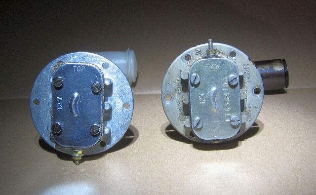 The new unit is on the left. Note the connector is on the bottom. 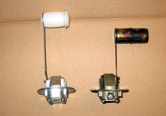 Top view. The float rod is attached to the spindle on the opposite side of the housing. I will check inside the sump to make sure there are no obstructions. The clip appears to be the same size so I should be able to switch the plastic float with the brass float from the original. 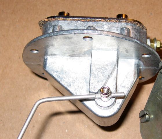 Removing the float rod on the new unit is really easy - it is held by a small allen screw. 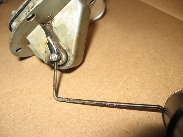 I wish the same was true of the original - I could just swap the float rods and float. Does anyone know how the float rod is held? Is it an interference fit? Is there any way I could remove it? | ||
Jim Walters Prolific User Username: jim_walters Post Number: 169 Registered: 1-2014 |
As the old unit is dead just carefully grind off the end of the shaft until you are really close to the arm. It should then be loose enough to tap out. Or cut it off with a hacksaw close to the body then carefully grind away on the thin sides where the arm goes through the shaft until it is free. SRH8505 SRC18015 SRE22493 NAC-05370 www.bristolmotors.com | ||
John Kilkenny Prolific User Username: john_kilkenny Post Number: 287 Registered: 6-2005 |
David, Thanks for the information. Have you heard the old saying "don't teach your grandmother to suck eggs"? | ||
John Kilkenny Prolific User Username: john_kilkenny Post Number: 288 Registered: 6-2005 |
Geoff, Before you give up on the old transmitter, I see that you have pointed out that the replacement is for a fuel gauge rather than an oil gauge. Swapping the floats is a good move and also check that the internals look OK for the harsher environment. John | ||
Alan Dibley Prolific User Username: alsdibley Post Number: 150 Registered: 10-2009 |
Geoff, have you considered that you might be lokking at the new unit upside-down, and the connector should still be at the top? Should be confirmed by checking the resistance variation with float movement. Alan D. | ||
David Gore Moderator Username: david_gore Post Number: 2915 Registered: 4-2003 |
"David, Thanks for the information. Have you heard the old saying "don't teach your grandmother to suck eggs"? Of course I have, however, I was preaching to a larger audience than yourself who may not have your in-depth knowledge. | ||
Larry Kavanagh Prolific User Username: shadow_11 Post Number: 177 Registered: 5-2016 |
The word "Top" is inscribed on both units. | ||
Geoff Wootton Grand Master Username: dounraey Post Number: 1968 Registered: 5-2012 |
Hi Folks I thought I'd wrap this thread up. I've had mixed success with the substitute, MGA fuel sender unit. I was trying to get it to work as an oil level sender unit. 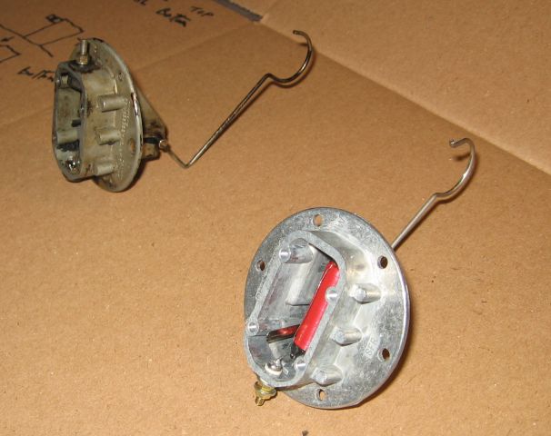 The float rod on the new unit has to be bent to fit in the sump however the clip is exactly the right size to take the original brass float. As might have been expected, the problem is the scaling is wrong on the new unit. This is because although both units have 80 ohm coils, the one on the new unit is longer than that on the original unit. 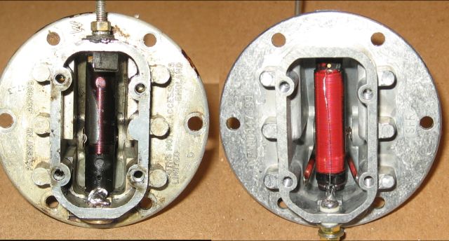 With the sump oil level just below the max mark, the coil is only measuring 47 Ohms, rather than 80. The oil level on the gauge is showing as just 5/8 full. In a years time when I carry out my next oil change I will try shortening the float rod to gear up the movement on the slider. It also occurs to me I could put a 33 ohm resister in series to get full deflection of the gauge, however that would then throw the min oil level out. A pic micro-controller with a/d and d/a converters on board would be really simple to program to map the voltage levels output by the sender to those required by the gauge, but unfortunately I sold off all my electronics stuff when I moved to the US 15 years ago. If anyone knows of a simple analog cirsuit to map the voltages I would be interested. Otherwise I will try changing the float rod in a years time. For now, it's great to be back on the road. | ||
Jim Walters Prolific User Username: jim_walters Post Number: 170 Registered: 1-2014 |
Hi Geoff, well I'm surprised that the coil is longer. Now that you have the old one to fiddle with why don't you measure the wire diameter and get some nichrome wire and rewind the coil? If the ohms are the same then the wire diameter must be slightly different if the windings are longer on the replacement. If shortening the rod will correct it you can just bend a 'Z' into it with pliers and that will shorten it. No need to take it apart and cut it. SRH8505 SRC18015 SRE22493 NAC-05370 www.bristolmotors.com | ||
Geoff Wootton Grand Master Username: dounraey Post Number: 1969 Registered: 5-2012 |
Hi Jim, You are a mind reader. That's what I intend to do over the next year, before the next oil change - re-wind the coil. If that fails I will look into shortening the float rod. Bending a Z into it is a great way to go as it means I will not have to straighten the bends I have already put into the rod, causing possible fracture. | ||
John Kilkenny Prolific User Username: john_kilkenny Post Number: 290 Registered: 6-2005 |
Geoff, Good try, bad luck it wasn't successful. If you get the coil rewound you wouldn't use nichrome (which is not solderable), The coil is probably single layer so you will need to specify the right length and resistance. There are copper and nickel alloys (both metals are solderable) which are used for this type of resistor. After that you would need a solvent to carefully remove the wire coating where the slider tracks. For the new transmitter to give a more accurate gauge reading, change the other resistor in the gauge. See diagram above. John | ||
Geoff Wootton Grand Master Username: dounraey Post Number: 1971 Registered: 5-2012 |
I dismantled the oil level sender unit yesterday evening with a view to rewinding the coil. It came out quite easily - the coil is supported by a groove either end of the core that locates in two slots in the housing. It was just a case of carefully pulling the coil out after I had removed the top terminal. The wire is 156 inches long with a diameter of 0.007". (4000mm x 0.1778mm). The thing is, at this length copper wire will not have sufficient resistance. The online calculators give 2.7 ohms. It looks like the wire is RW45 nichrome, which will give around 80 ohms. I checked out the problems with soldering nichrome. It seems one approach is to just encase the wire in solder to get an electrical contact. I will research this further but it looks like I have to go with nichrome. | ||
John Kilkenny Prolific User Username: john_kilkenny Post Number: 291 Registered: 6-2005 |
Geoff, Check out suppliers of "Constantan" insulated resistance wire. It is a copper/nickel alloy and comes in different grades. It is possibly the one used. Incidentally when you unwound the wire did you find the break ? John | ||
Geoff Wootton Grand Master Username: dounraey Post Number: 1972 Registered: 5-2012 |
Hi John Thanks for the tip - constantin wire - I'm having trouble finding wire I can purchase of the right resistivity. I shall research it tomorrow. There was a break in the wire. The first length was 74" and the second length, 82". Total = 156" inches in real money or just under 4 metres, if you prefer. From the online tables 33 AWG nichrome 45 would work at approx 20 ohms per metre, but so far, I cannot find anywhere that sells it. I may have more luck with constantan insulated wire. Thanks for all your help |