| Author | Message | |||
Daniel Shepherd New User Username: 1957_grey_cloud Post Number: 23 Registered: 12-2021 |
The XJS let me have some Cloud time this weekend, so the front-end rebuild was resumed. Put new belts on, the new Bentley-branded belts have teeth whereas the old ones didn't. Hope that's okay... Need to get the horns on next, but when I depress the horn switch in the interior I can't hear any clicking from a relay. Any tips with removing the horn button-press off the steering wheel, and whereabouts in the in engine bay might I find the relay? Re-cored radiator going in next weekend, I hope :-) Cheers Daniel 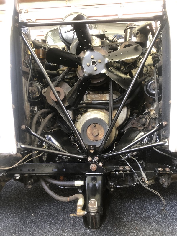 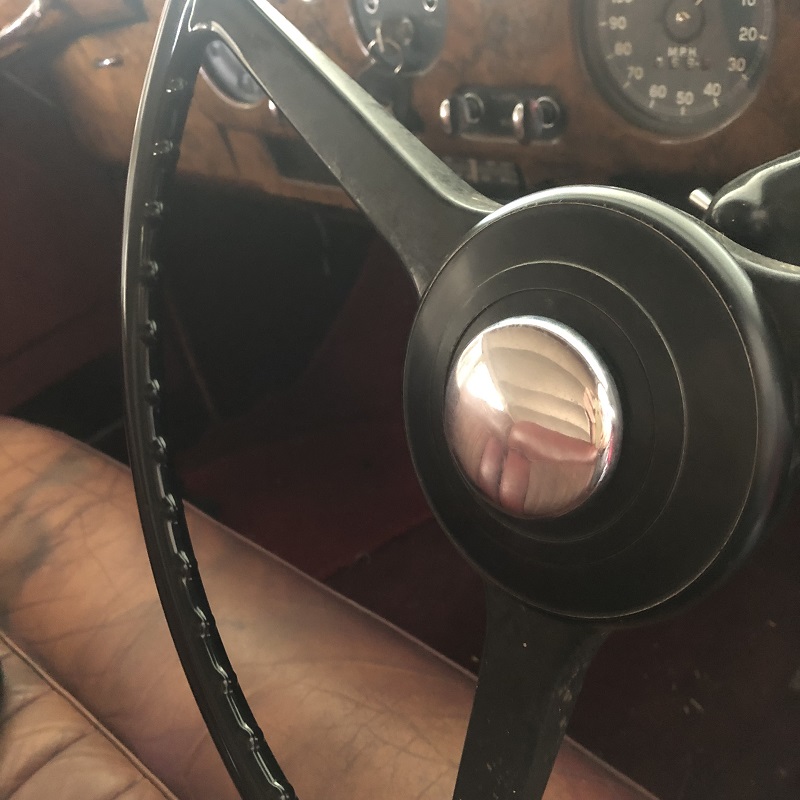 | |||
Jeff Martin Frequent User Username: jeff_r_1 Post Number: 440 Registered: 07-2018 |
https://rrtechnical.info/sc/sc1/spares/11.pdf Page No. K-29 Looks like there are 3 cheese head screws from behind, #25. There should be a wire coming out the bottom of the steering column, follow that to the relay.  Looks like the horns have their own fuse as well (black wire). https://rrtechnical.info/sc/sc1/wshop/s1weh.pdf . | |||
Daniel Shepherd New User Username: 1957_grey_cloud Post Number: 25 Registered: 12-2021 |
Thanks for the wiring diagram Jeff, I'll be printing that out at work tomorrow! I traced the wire back to the horn fuse, but things get murky from there with relays all over the place, and some look quite agricultural. Hopefully the colours in your diagram will hold true for our boy. I'll test the horn-push first and go from there.... Cheers Daniel | |||
Jeff Martin Frequent User Username: jeff_r_1 Post Number: 441 Registered: 07-2018 |
You need to get yourself a multi-metre, and perform some continuity tests to find out which relay it is. That's just basic circuit tracing. The battery should be disconnected when tracing circuits. With the wiring diagram in front of you and the multi-metre, it's pretty straight forward. You can check the fuse as well, doing just a visual check is not reliable. Also look for oxidized connections at the fuse too. | |||
Jeff Martin Frequent User Username: jeff_r_1 Post Number: 443 Registered: 07-2018 |
There's an 18 way junction box with black wires coming in and out of it and it appears that those are the only black wires. One runs from the bottom of the steering column, and the other goes to the relay. Doing some continuity tests will tell all. Note too on C2 there is a capacitor there to keep the relay from arcing, with all the relays you found, at least one will have a capacitor connected to C2. If there is not capacitor, someone may have removed it (for what ever reason), and this would cause excessive arcing to where the contacts inside the relay no longer make a connection. That may be part of the problem. What I've learned over the years when it comes to car wiring (or anything), there are usually numerous points of failure that have to be addressed. One has to methodically and logically go through the entire circuit eliminating and repairing the causes, don't assume anything, disconnect the horns from the 12 volt source from the car, but leave the ground connected (if there is one). Once disconnected, put an external 12 volt source on the horns, to eliminate that from the equation. We're into restoration of the circuit, not just repair. | |||
Daniel Shepherd New User Username: 1957_grey_cloud Post Number: 26 Registered: 12-2021 |
Thanks for the good advice John, I've borrowed the Fluke from work for the weekend and I will follow your guidance. As a rookie I didn't know that I would need to disconnect the battery - learning all the time. I've also tried to make a bit of a map based on the wiring diagram you sent me, three fuse it seems! I'll report back. Cheers Daniel 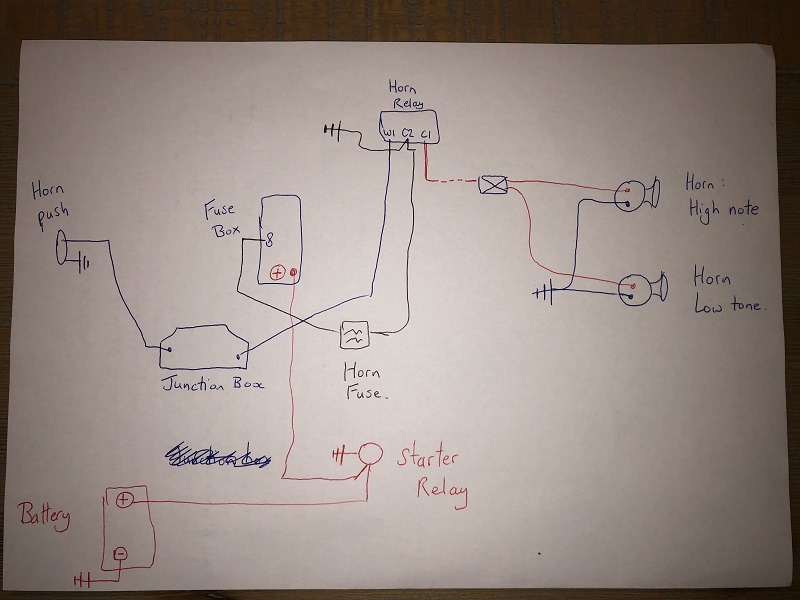 | |||
Jeff Martin Frequent User Username: jeff_r_1 Post Number: 444 Registered: 07-2018 |
When I do continuity testing I like to have the battery disconnected, but you can also have it connected and check for 12 volts through the circuit, and I think I'll have you do it that way. Do you know what a continuity test is first off, I need to know for sure ? Disconnect the live side of the coil (positive side) as the ignition may be on for some time while testing, this is disconnected to keep the coil from over heating if the points just happen to be closed. Make sure that this disconnected wire from the coil does not come in contact with a ground or anything else _ it is live with the switch box on and the ignition switch is on. With the battery connected, the cars switch box turned to "ON" and the Ignition switch is "ON" use a test lamp or a volt metre, to measure and make sure that there is 12 volts at terminal 8 on the cars main fuse box in your wiring diagram. If there is, test that there is 12v at "C2" on the horn relay, if there is not, then the horn fuse is "OPEN". Deal with that and make sure that there is 12 volts at C2. If there is still no voltage at C2, even after you replace the horn fuse, then check the connections to the fuse with in the horn fuse box. There has to be 12 volts at C2. Once you have determined that there is 12 volts at C2 and the horn does not work, I suspect that the relay is at fault. To test that, disconnect the spade terminal at "C1" (according to the wiring diagram it is a red wire). Connect a 12 volts source to the disconnected wire from C2 and to ground _ the horns should sound. If they do not, then there is an open circuit from the red wire from C2 to the horns _ usually a band ground at the horns. Once the horns are working from you 12 volt test, and the horns still do not work, then that will point to a faulty relay, or a bad ground connection from the horn button on the steering wheel to W1 on the horn relay. You may disconnect the wire at W1, and ground that terminal at W1, if the horns sound, then there is a bad ground or a bad connection from the horn button to the wire that connects to W1. If the horns sound in this case, the horn relay is Working correctly. Do these tests for now, and I'll write more on how to make sure that the relay is being properly grounded through the horn button on the steering wheel. You may also test the relay, and if you want, I will tell you how to do that too. One more thing, the ground you have from C2 is not a ground, it is a capacitor, if it were a ground, it would be a dead short and the horn fuse would blow immediately. See my screen shot, the symbol with in the red circle of the two lines is the symbol for a "Capacitor". The terminal at #8 is a live 12 volts from the switch box, it is not fused there. It gets its 12 volts when the switch box is turned ON, and when the Ignition switch is ON. Someone may have thought it was a ground at C2, and that would instantly blow the horn fuse _ the horns would not work of course and it may have been left that way.  | |||
Jeff Martin Frequent User Username: jeff_r_1 Post Number: 445 Registered: 07-2018 |
I'll correct some more on your drawing tomorrow, 12 volts does come from the starter relay, but does not flow through a fuse in the fuse box to terminal 8, and goes to the switch box (and amp meter). Then from the switch box to terminal 8. There is no fuse in the fuse box for the horn, just the horn fuse, and according to the wiring diagram, it may be using 2 fuses, very odd if it is. I'll see if I can get a big enough screen shot of the wiring diagram and highlight which way the current is flowing and to where. It's almost 1:00 A.M. here now. I can sleep late if I want too.  | |||
Jeff Martin Frequent User Username: jeff_r_1 Post Number: 446 Registered: 07-2018 |
I'm correcting your drawing, the 12 volt feed wire that comes from the starter relay does not feed the entire fuse box, it only supplies 12 volts to fuse "4". It continues on from the junction terminal of fuse 4 to the switch box; terminal "4" at the back of the switch box. I realize now that they are not "FOUR's", but "PLUS" signs. That fuse supplies 12 Volts to the electric clock (from what I can tell), cigar lighter, boot lamp switch and boot lamp, as well as the door switches and roof lamp. Looks like a purple wire. I've high-lighted the 12 volt feed in "YELLOW" with "BLACK POLKA DOTS" and have arrowed in the flow of current with yellow and black arrows. There is another wire from terminal + at the switch box that goes to the Ammeter and then to the generator, but you need not concern yourself with this as it has nothing really to do with the horn circuit, at least not directly. Generally all 12 volt feeds come from the switch box and feed the various circuits into the fuse bar. (note, if you right click and save the image on your computer, you can enlarge it some-what and see my print better, the site only allows a maximum resolution of 800 x 800 pixels, which is too small) | |||
Jeff Martin Frequent User Username: jeff_r_1 Post Number: 447 Registered: 07-2018 |
 | |||
Jeff Martin Frequent User Username: jeff_r_1 Post Number: 448 Registered: 07-2018 |
Here's the entire horn diagram in better resolution. I've changed the horn circuit to red with green diagonal lines to make it easier to see. There are green arrows with red outline to show the flow of current to the relay. I've also improved the resolution of the capacitor symbol at W1 The horn circuit starts at terminal "8" at the switch box to the left of the diagram. Take all of this a step at a time, study and understand it, hopefully you won't become overwhelmed. https://1drv.ms/u/s!Ak1aw8qrdXdhtGQ7sv3DcgbNQ9oz?e=6vPv5q | |||
Daniel Shepherd New User Username: 1957_grey_cloud Post Number: 27 Registered: 12-2021 |
Thanks so much for this Jeff, I'm going to print out your instructions and wiring diagram at work today and then systematically work through the circuits. I should be good with a continuity test, the meter has a lovely tone that utterly screams 'closed'! So I took the opportunity to plumb the re-cored radiator back in yesterday: 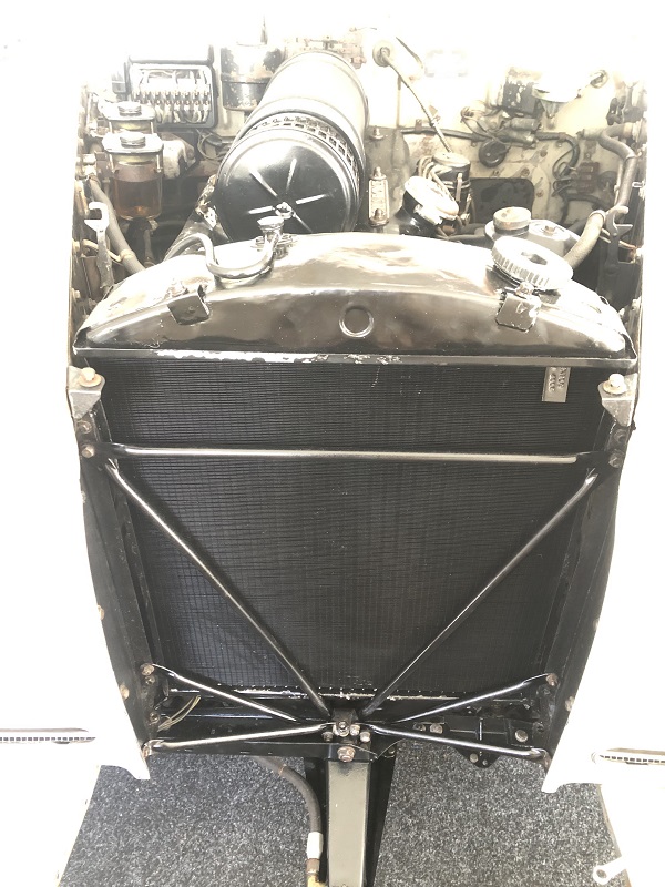 | |||
Daniel Shepherd New User Username: 1957_grey_cloud Post Number: 28 Registered: 12-2021 |
Also, regarding Terminal 8, am I at the wrong fuse box, or am I missing something completely obvious to everyone except me!?!?! Note the smaller fuse box to the right is for the horn, and it does indeed contain two fuses: 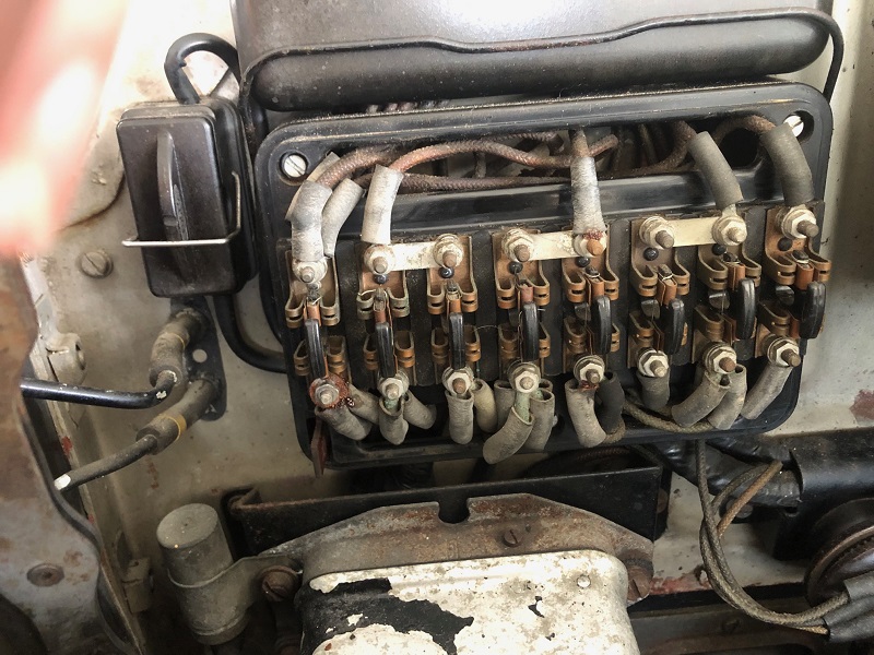 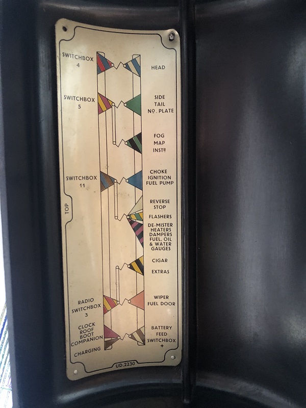 Thanks again for all you help Daniel | |||
Daniel Shepherd New User Username: 1957_grey_cloud Post Number: 29 Registered: 12-2021 |
P.S. And thanks for pointing out that the diagram in fact shows a capacitor and not an earth! I did wonder why that earth was there, so I'm slowly learning! This relay here is the likely antagonist - so I've some landmarks to navigate off now :-) Best Daniel 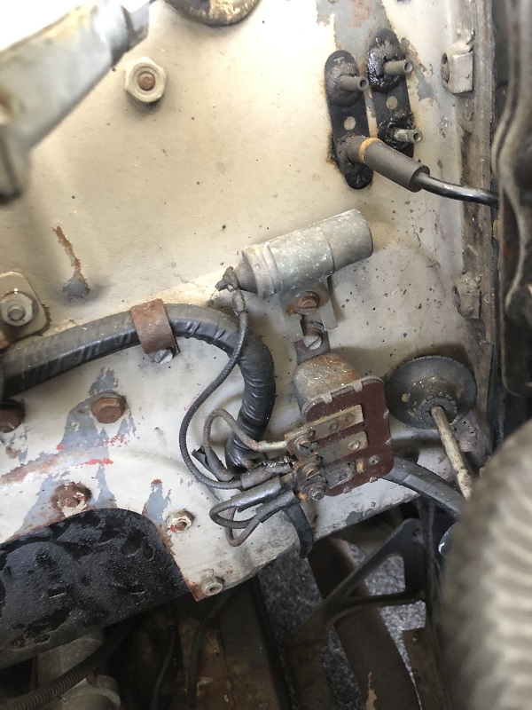 | |||
Jeff Martin Frequent User Username: jeff_r_1 Post Number: 449 Registered: 07-2018 |
The wiring diagram is different than what is in your car, Terminal 8 is not there in your fuse box, and even if it was, all the braded wiring is so dirty and faded, you can't see any colour. Sometimes you can take a Q-Tip and clean a not so dirty area with acetone, Lacquer thinner, or paint thinner. For now, forget about the wiring diagram, we'll do the trouble shooting with out it, at least we know where the horn relay is and the double fuse box for it. We need to determine which terminal is which on the relay, the centre one is C2 for sure as it has the capacitor running off of it. Get the volt metre setting for 12 volts DC on your multi metre. Turn the car ON and the ignition ON. Check that there is 12 volts at C2 on the relay. If there is not, one or more of the horn fuses is blown. (one may be just a spare fuse, but I'm not sure about that) At this point you may want to clean up the terminal connections on that fuse box, remember to disconnect the battery when doing this. When you have 12 volts at C2, post back and we can continue. Also look carefully on the back of the relay, it should be marked W1, C2 and C1, If you can see that it's marked, that makes thing a little easier. Let me know what you find.  | |||
Daniel Shepherd New User Username: 1957_grey_cloud Post Number: 35 Registered: 12-2021 |
Cheers Jeff - Drowning in the end-of-year work panic right now - but I see my previous two posts didn't work! Looks like a Lucus SB 40 if the internet is to be trusted... The butcher who put the air horns in whacked in spade connectors, so I need to get some bullet connectors this weekend. But if I'm reading you right, I can disconnect C1 and briefly touch it to the C2 terminal as a test? Cheers Daniel 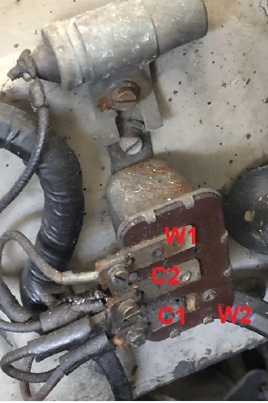 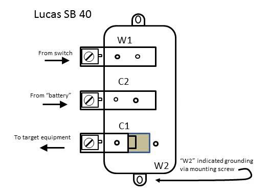 | |||
Jeff Martin Frequent User Username: jeff_r_1 Post Number: 451 Registered: 07-2018 |
Yes... On my car (51 Mk VI) I have to have the car and the ignition ON for that test to work. It may be the same for your car, but because the wiring diagram does not match, I can't say. Try with the car and ignition OFF, and then ON. If your test works, then it could point to the relay as the fault, and or a bad ground, internally or externally. The connections need to be cleaned up as well. If you want to test the relay, ground terminal W1, that will by-pass the horn button. This assumes that there is 12 volts at C2. When I was doing my car, I restored the bulk-head (fire-wall). I took the opportunity to clean up the fuse box and all the wiring in the car, since to remove the bulk-head, all the wiring had to be removed from the fuse box and the large junction box above it. I found lots of questionable connections. Here it is now:  I'm not saying that you should do this, but the car is 78 years old, from my experience when it comes to wiring, or any system on the car, having one thing going wrong in a car that old is very often not the case, it's many things. If your test doesn't work, it doesn't narrow things down enough. It tells you that there may not be 12 volts at C2, the horn circuit is open, the horns are faulty _ bad grounds... | |||
Daniel Shepherd New User Username: 1957_grey_cloud Post Number: 36 Registered: 12-2021 |
Reporting back on this - apologies for the time lapse - I caught a nasty bought of COVID at the end of November and with Xmas/New Years I've only just had the opportunity to start working on the car again. So I followed Jeff's advice above and he was spot-on. Cleaning the relay and the wires made a big difference. We now have "beep-beep" at the horns :-) Thanks all for the guidance, I really learnt a lot from this little episode. Time to put the grill back on! Daniel 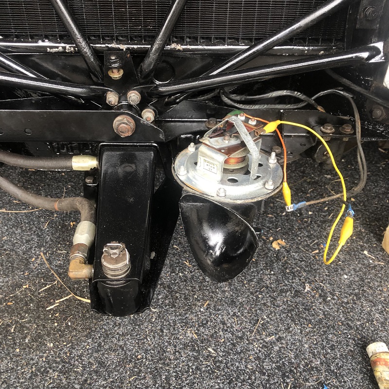 | |||
Daniel Shepherd New User Username: 1957_grey_cloud Post Number: 37 Registered: 12-2021 |
Reporting back on the horns on our 1957, which had been replaced at some point with dysfunctional air horns. Sorry for the delay - a nasty bout of COVID in November and then the silly season has stopped me from getting into the garage. I followed Jeffs advice given above, and it was spot-on. Cleaning the relay and circuit definitely helped. We now have a pair of Lucas 1953 windows happily beeping away. I've attached the manual for these. Now for the front grill! Thanks for everything, I actually learnt quite a bit from this episode :-) Daniel 
| |||
Jeff Martin Frequent User Username: jeff_r_1 Post Number: 473 Registered: 07-2018 |
That horn is nice and clean inside, they can be very corroded and rusty when the cover fails. The covers seal gives way and/or a tiny rust hole lets salt and water in. | |||
Daniel Shepherd New User Username: 1957_grey_cloud Post Number: 38 Registered: 12-2021 |
Opps, sorry for the double post - I thought the first one had failed! I'll get those covers on and hopefully the grill in place before the month's end. Then I am going to get it trucked to the mechanic. Thanks again for all your help Jeff. |