| Author | Message | |||
Jeff Martin Frequent User Username: jeff_r_1 Post Number: 547 Registered: 07-2018 |
It begins... My block does not have the centre plate, but a core plug, and I'm in the process of locating the tool to get that out. I don't know why the core plug is in there rather then the plate ? I've contacted Kelly at British Tool Works to see if one of these work: https://www.britishtoolworks.com/product-page/screw-in-freeze-plug-pin-socket Flying spares has also has these for rent, as well as some other options, see here: https://www.flyingspares.com/loan-of-core-plug-spanner-rh617loan.html When I did the engine some 25 years ago now, I was told that the water jacket was OK and to leave it alone, but now when I look at it, I could have spent time cleaning the bottom out. It does not over heat, and what is in there now has always been in there, I've looked after it well since the rebuild. I did remove all the core plates, including the rear one and replaced all the screws with stainless steal at the time of the rebuild in case I had to get them off, but it was not necessary to remove the one at the rear at this time, there's nothing there to clean. I'll have to contact Flying Spares to see if that core plug tool in the second link is the correct size. About rust dissolvers: Looking at this one; and there are many on the market like that do the same thing, they claim it only attacks the rust _ not sure how that works, but I've had bad experiences with acid rust removers. Products like Evapo-Rust claim it will keep on eating away at the rust until it reaches good metal if left long enough and one keeps changing the solution out. That would imply that even long solidified silt will be eaten away, but I have my doubts about that, I'm going to find out. This will be a huge job as I want to remove the brass coolant tube, and as you know, this will require the removal of the rad, and everyone here knows what that means. Taking the front of the car apart will probably be necessary to get the core plug out anyway. https://www.tenaquip.com/product/crc-canada-evapo-rust-super-safe-rust-remover-pail-er019-ah143?gclid=EAIaIQobChMI78qCyObSgQMVjRatBh2BAwPXEAQYCCABEgJR6PD_BwE 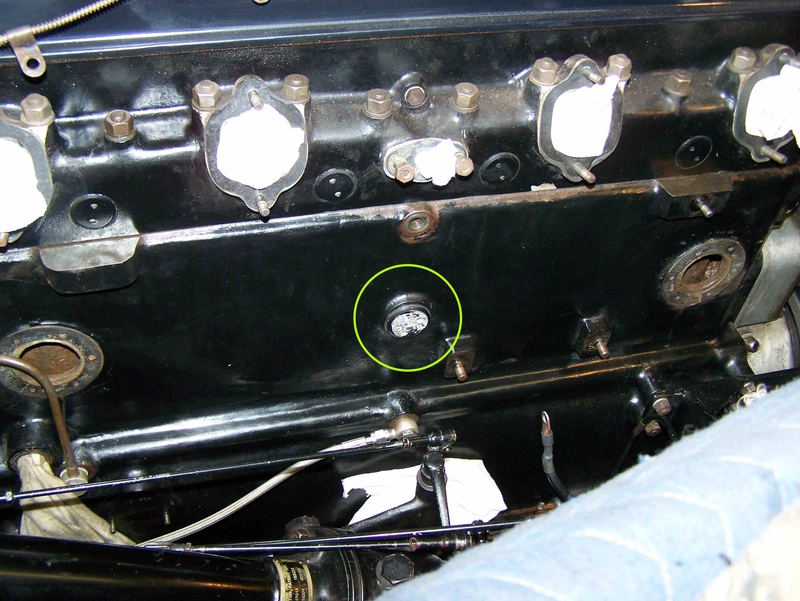 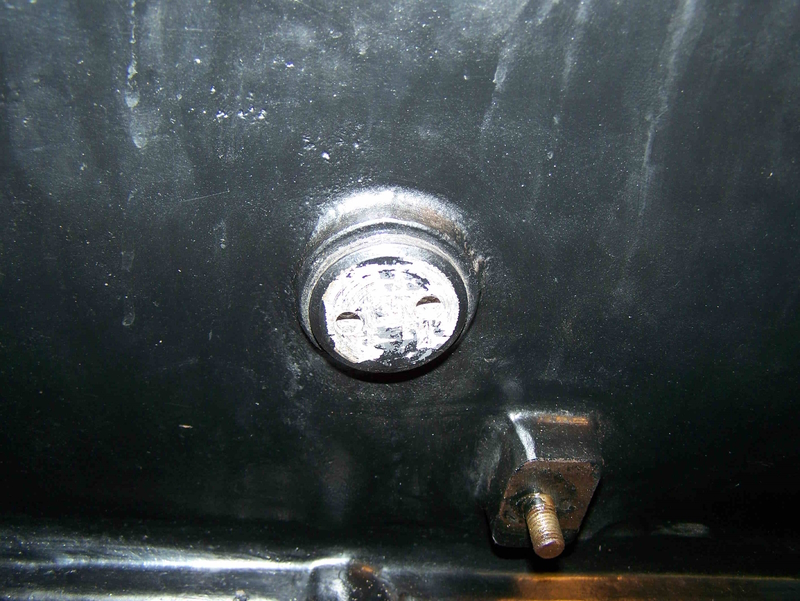 . | |||
marktaxis Unregistered guest Posted From: 1.156.188.39 |
I used this product, seemed to work well https://liquidintelligence.com.au/ (Message approved by david_gore) | |||
Jeff Martin Frequent User Username: jeff_r_1 Post Number: 548 Registered: 07-2018 |
Thanks Mark, That's a waterless coolant, we have something similar here too, but I'm more interested in cleaning out the debris on the bottom of the block. (EDIT: I guess you meant this product Mark); https://liquidintelligence.com.au/products/organic-rust-remover#buy I keep finding particles of it in the system; here are some photos the way it sits now. The head is off where I can get a tool in there to break it up, after which I plan on rigging up the garden hose and flushing out the bulk of the debris. The car doesn't overheat per-say, but I think it will benefit from a good descaling _ that would make the heat transfer more efficient. The distance between the bores are open and one can see the join in the casting between the bores _ the back end is clear except for the muck at the bottom of the block. The middle of the block has enough mud where the coolant is puddled and will not run out the blocks drain hole _ I intend to fix this. All of this was never cleaned out at the machine shop, they did not want to boil the block because that would have destroyed the cam bearings _ they didn't have the tool to line bore it. They were done not that long ago, they were measured and found well with on spec, the same with the lifters. I should have cleaned the block out by hand at the time, but it never occurred to me. After 20 years, the head was yet another bitch to get off, and like last time, one stud was holding it in place _ I will use a thread sealant this time around for the next guy; in another 20 years, I will be 78, if I last that long. 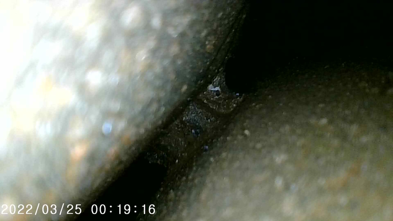 Bores 6 and 5 with the casting in between.  Coolant puddled in the middle of the block. 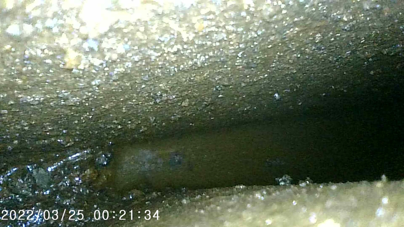 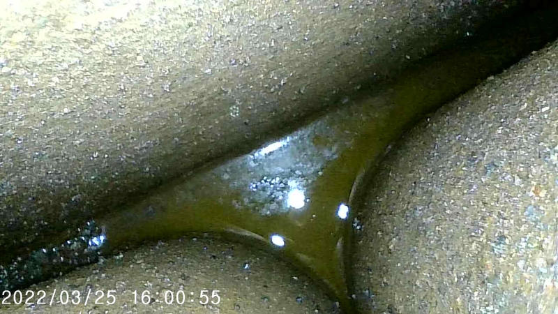  Bores 1 and 2 . | |||
Jeff Martin Frequent User Username: jeff_r_1 Post Number: 549 Registered: 07-2018 |
About the plug on the side of the block, the link to Flying Spares is for the V8, and when I contacted them, they said "none of them will work on the straight six" They're Kelly Opfar's tools incidentally. (British Tool Works) Flying Spares does not have a proper fitting pin wrench to RE9016, the number for the plug according to the service bulletin on pages BB-65 and BB-65a. https://rrtechnical.info/mkvi/r/bull/4.pdf I'm working with Kelly to produce the correct size pin wrench. I plan on the Evapo-Rust soak before an attempt to remove the plug. This is interesting: https://www.youtube.com/watch?v=6-MC_ZEXQbw | |||
Jeff Martin Frequent User Username: jeff_r_1 Post Number: 551 Registered: 07-2018 |
This is the camera I used to take the photo's: https://www.amazon.ca/dp/B0C3H1N8VQ?ref=ppx_yo2ov_dt_b_product_details&th=1 I'm not going to worry about the debris seen in the photos, the Evapo-Rust will take of that. The car needs to be pointing up hill for things to run out at the rear, and that's not possible as its up on blocks at this point. A huge amount of sediment was trapped in the front of the block, unfortunately there is no easy way to get the garden hose in there, other then to remove the front casting plug. Over-all it's as clean as it's going to get as well as I can get in there. 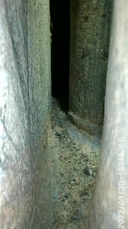 Looking down from the front of the engine. 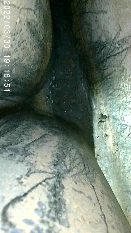 Rear of block. 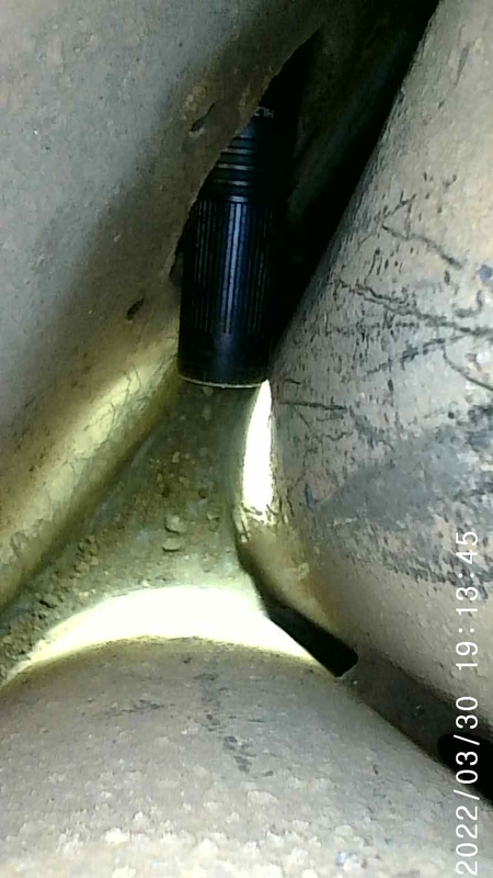 Front of block. | |||
Jeff Martin Frequent User Username: jeff_r_1 Post Number: 553 Registered: 07-2018 |
https://kda132.com/wp-content/uploads/2018/04/Ravages-of-Time.pdf This area on my block was filled right up with rust particles and what looked like brown dirt. It's a nasty area because it's well below the blocks drain hole, and as I mentioned earlier the car has to be parked on a hill for this to drain out. I can't tell if it just dead-ends here or if coolant is allowed to flow around bore #1, Norman would hopefully know, if I can get the brass water tube out, I may be able to tell and even get in there to clean it better. From what looks like an improvement when RR went to the 4.5 litre engine, doesn't at this point. In order to accommodate the larger bores, the rear bores were siamesed together and the front bore was moved closer to the outside of the block creating this very narrow area which made it very difficult to remove the sand after casting. Even if the sand was properly removed, this very tight area would be prone to the accumulation of rust and silt. Why didn't RR make the block longer, or maybe they did, but not long enough. The cavity on mine appears much larger then the photos shown here.   | |||
Jeff Martin Frequent User Username: jeff_r_1 Post Number: 554 Registered: 07-2018 |
And the response from Evapo-Rust after I asked them if putting a block heater in there is a good idea to augment the chelation process: "Thank you for choosing CRC Products. A block heater is a wonderful idea. Temp is a critical factor in the performance of Evapo-Rust. 65 is minimum, but the warmer you can get it, the more effective it is and the faster it works. 90-100 would be ideal. Please let us know if you have any questions". | |||
Jason Watson Experienced User Username: crikeydawn Post Number: 76 Registered: 07-2023 |
So your looking to devolve then flush. Looking at ol mates videos muriatic acid then krud cutter or even CLR are better than Evapo-Rust. Good on the you tuber for doing the experiment as it does point out a few differences. Would a diluted muriatic acid be of worth, then lots of water to neutralise. You could fill the block completely and cheaply and not have to wait for ages. All done and dusted on a nice sunny day. Wet the floor underneath for any spillages so it doesn't spot clean. Also wondering if an air hose blower can be fitted to a garden hose. Where the long nose of a blower could be poked down a sleeve and create the pressure and jet like motion to help move the tighter sections. Or maybe two, one air one water. I do like your camera, reckon I that would be great to check chassis internals and have at look my block also. | |||
Jeff Martin Frequent User Username: jeff_r_1 Post Number: 555 Registered: 07-2018 |
I already have the 13 Litre pail of Evapo-Rust; and I don't mind waiting. Muriatic acid at any strength is a big thumbs down, yeah; it would work, but I found from personal experience that it can never be totally neutralized, things always rust over no matter how much baking soda and water is used. I can prevent that with WD-40, but the gas-off rusts everything in sight _ ask me how I know this.  I use the stuff outside far away from everything, and that's it _ can't get the car out of the garage _ too cold and wet anyway. I could see the stuff destroying the deck, I found to matter what steps are taken, it gets into everything. The block heater thing should work really well, another tuber said he heated the block up and it was very effective. | |||
Bill Vatter Experienced User Username: bill_vatter Post Number: 162 Registered: 09-2004 |
I have cleaned several blocks but I did not use any chemicals. Some blocks will have very hard deposits, essentially scale mixed with rust that is very like rock. For that I used chisels, cut-off hacksaw blades, and other selected tools to chip away at the scale. After chipping awhile, I took the block outside and used a pressure washer to clear out whatever had become loose. I was careful not to let the water jet impinge on the brass water gallery, which would not withstand that. The worst one took a couple of weeks working 3-4 hours each day to get it cleaned up. Getting around back of the cylinders is difficult, and more so for 4-1/2 litre blocks than 4-1/4 ones. The 4-1/2 blocks are closed between cylinders 1&2, 2&3, 4&5 and 5&6. However, that isn't your very early block. Access behind is possible through the ports at the back of the tappet chamber. Those will require a pin spanner like Kelly has for sale and Flying Spares has for rent. Other blocks had softer deposits. Hard or soft deposits depends on water hardness. If the car lived where the water was hard or naturally soft, you got hard or soft deposits. Soft deposits are easy to remove. You just wash then away with the pressure washer. Your block looks really good. There isn't much hard scale on the cylinders. Scale will always plate out on the hottest places. How much is at the bottom isn't very critical. The bottoms of the cylinders aren't heated much if at all by the combustion, so if there is a layer of crud at the bottom, it won't affect cooling. You do, however need to have a flow path to the block drain. Lots of engines have considerable build-up of crud at the bottom of the water jacket. The way to tell is to open the drain. If water flows out freely, all is well. If not, you need to work whatever into the drain to open up a flow path, and cleaning out the water jackets is also needed. Some blocks will need to have the drain valve and adapter removed, and then work a coat hanger into the hole in the block to drain old coolant. Some engines haven't had a coolant change in a VERY long time. Those will also be the ones with lots of crud in there. | |||
Bill Vatter Experienced User Username: bill_vatter Post Number: 163 Registered: 09-2004 |
If you hot tank the block with caustic soda, that will indeed dissolve the camshaft bearings and anything aluminum on the block. Early blocks like yours have aluminum core plugs, So if you do that, you will need a complete set of new core plugs and also new camshaft bearings. It is one way to get your core plugs out. Later blocks have steel core plugs. It is not necessary to use the camshaft bearings made specifically for these engines. You get camshaft bearings with the same OD, which I forget, but it is in the literature somewhere. Then you root through the catalogs to find some bearings with that shell outside diameter. Exact width of the bearings isn't important. You can stack up the bearings for extra width, and if a bearing hangs out the end of the block hole for it, that doesn't matter, as long as it doesn't interfere with something in there like a cam lobe. You also don't need to line bore the bearings. The factory didn't do that, they used a reamer. A reamer with appropriate tackle to keep it on center is all that is needed. I bought a shell reamer and mandrel of the appropriate size and made the rest of the tackle to reamer the bearings. I will loan that equipment and provide instructions if you want. It does a very good job. Norman inspected the results and said it was "very good." | |||
Bill Vatter Experienced User Username: bill_vatter Post Number: 164 Registered: 09-2004 |
Oh wait!!!! Those last two photos of the gear case don't look really good after all. That huge hole between the gear case and the water jacket!!! What happened there??? You are going to have to find a way to close up that gaping hole, if it can even be done. That block is probably toast. Time to start looking for a new block. | |||
Jeff Martin Frequent User Username: jeff_r_1 Post Number: 564 Registered: 07-2018 |
That's not my block, that's from a post of Norman's blog. The link to that article is in that post, sorry for the confusion. I was asking is that a dead end area, or does the coolant flow around the front of cylinder #1 ? I can't tell, it's not possible to get my camera in there. I thought Norman could answer that question since that was a block he did _ I think it was his. The engine is still in the car and the idea was to clean it as much as possible, with out having to dismantle it. I would like to get the brass water conduit out of the block and modify the holes, but that may not work out as I can't get at the back. I do remember taking it out some 25 years ago when the engine was done, it slid right out. If I try to force it out from the front with hooks, I would end up destroying it, but I think Flying Spares has a new one. When I use Evapo-Rust product, it may remove enough of the surface corrosion so it would slide out, I'll find out. I just want it as clean as possible and the Evapo-Rust product kills the rust with out eating at the good iron _ so it says. The block heater I installed will ramp the chelation process. I'll post some photo's later the way the car sits and how I installed the block heater. Thanks for the loan of the ream tool, I appreciate that. I did buy some camshaft bearing shells, but the machinist didn't want to tackle the job anyway as it was well with in spec. He also added some exhaust valve seats as there was no material left from over-grinding. After 21,000 miles the whole things is doing well. I could never get the thing to idle where it would just sit there to balance a coin on it, everything I do helps, but not cure it. The only thing left is the camshaft; I'll check the lobes, and it's timing, another big job to get that out, but I've gone this far. There's a cam grinder on the Main Land (Vancouver Canada B.C.) that has done these before, much less expensive then a new one at around �1900.00 Jim Walters has used them. The shop also has the ability to add material and harden the surface again if need be. When I did the engine I was in my early 30's, there was no internet, and even if there was, I had no computer, all I had was a reprint of the RR manual from the RROC. I timed the camshaft by applying compressed air to the #1 cylinder and waited for the sound to change when the valve started to open, I didn't know at the time about spinning the push-rod back and forth and don't think the manual said anything about that. I would have to look again to be sure. I'm going over things now and correcting mistakes that I made back then. If the weather is around 20c in the spring where it can be warm and humid, the car runs very well. When I drove to a meet the engine was well wormed up and later when I started it again for judging the heat sink warmed up the manifold and it did idle very well; nice even exhaust notes and the engine stood very still. It doesn't like very hot days either, it can idle sort of rough too. | |||
Jeff Martin Frequent User Username: jeff_r_1 Post Number: 566 Registered: 07-2018 |
Block with Evapo-Rust in it with block heater. 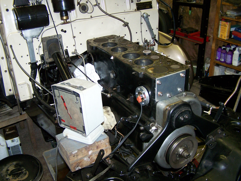  | |||
Jason Watson Experienced User Username: crikeydawn Post Number: 81 Registered: 07-2023 |
Its like waiting for cake to bake......and then finding if it turned out perfect. | |||
Jeff Martin Frequent User Username: jeff_r_1 Post Number: 568 Registered: 07-2018 |
 Yeah, isn't it. My hope too is that the Epavo-Rust will get in around the threads of that side plug and make the removal much easier. The 600 watt block heater warmed it enough where I could not keep my hand on it, and that should also aid in the extraction of that plug. It would make a very interesting experiment to get a block that's very choked with rust and silt to where it has to be chiseled out of there. The silt is made of iron rust, aluminum oxide, some brass oxide and I'm sure what ever is present in the recipe of iron the block is made from. In theory the rust particles should be eaten away allowing the solid blocks of silt to disintegrate as the rust is turned into this black sandy like substance. | |||
Jason Watson Experienced User Username: crikeydawn Post Number: 82 Registered: 07-2023 |
You got me curious. My block still awaiting completion was caustic cleaned in 2011. Looks like success but still some detailing to do. Its on a motor stand and rotates, so hopefully that will make things easier. from down the jackets top of block 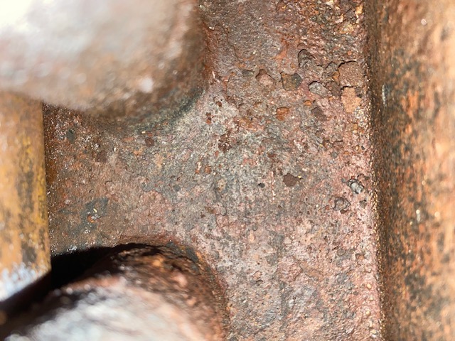  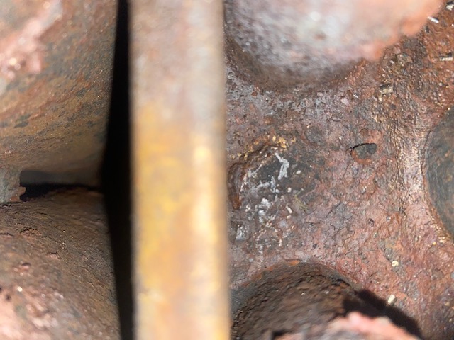 between cylinder 3-4  Cover plate at end of motor. 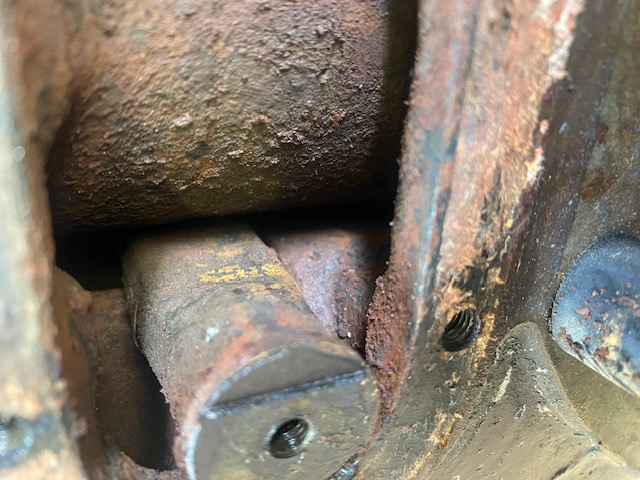  . | |||
Jeff Martin Frequent User Username: jeff_r_1 Post Number: 570 Registered: 07-2018 |
Have a read of this, in case you already haven't done so. "Type D Gallery Assembly" and "Later Developments" It talks about lengthening the holes in the gallery to distribute the coolant better. Norman's figures in the before and after table are impressive. If you plan on doing something with the gallery, now's the time. https://kda132.com/wp-content/uploads/2018/04/Cylinder-Blocks.pdf "About Caustic Soda & Acid Based Solutions" I found with any of these acid based products that neutralizing them is very difficult, I believe this to be so because no matter how much the block is rinsed with water, and/or water and baking soda, there are always traces left behind of the acid product left in the pores of the iron. I've cleaned parts outside in a bucket using straight Muriatic acid, and even after days of soaking in a solution of baking soda and water, and rinsing, things still can turn yellow and get a rusty film on them. Only after spraying things down with WD40, and then getting rid of the WD40 with an oil based engine degreaser and more rinsing, do the items stop rusting over. At this point I can paint them. If that were my engine I would use something like Evapo-Rust or some such product that neutralizes any traces of acid and rust where it turns the iron black. I did drain my block to check things out and there is this black film on everything, some of it kind of slimy yellow, I can't get in there and scrub it so I'm still reading up on how to remove that. So far I've come across that I should leave the product in there longer, and that's where I'm at now. It just may rinse away with paint thinner or WD40, I don't know yet. There's a technician that I have been in contact with at Evapo-Rust looking into this. | |||
Jeff Martin Frequent User Username: jeff_r_1 Post Number: 571 Registered: 07-2018 |
Here's a photo of the new water gallery for the 4.5 litre engine. If that's an actual photo it shows the holes at the end are smaller then the front. I find this odd as this goes against what Norman did to his gallery. They claim that this is improved and that makes no sense to me.  | |||
Jason Watson Experienced User Username: crikeydawn Post Number: 83 Registered: 07-2023 |
Feeling blessed the 4.9 has the smaller pulley and larger fan. I think that looks right though, but without measuring who really knows. Page 26 or Normans report for modified C - D type indicates hole 5 - 6 are smaller than 4 - 5, which are smaller than 1-2. The annoying thing is hole 1 is smaller on the modified galley opposed to the OE C and D. Not sure I could rats to buy a new galley just for one hole, when the other 5 are simply made larger. Guess one could braze hole 1 a tick smaller. Maybe try the wreckers for a galley out of cooked 4.5. Or 4.9 if the mount is the same as my pic on the rear cover plate. | |||
Jason Watson Experienced User Username: crikeydawn Post Number: 98 Registered: 07-2023 |
Jeff, been looking into electroplating and came across this scientist that experiments with multiple common acids for rust removal. https://m.youtube.com/watch?v=5Bkdej_z1HI&t=49s He also has another clip mixing hydrochloric - muriatic acid 50% to clean bolts. One thing I have noticed over all the clips I've watched is no one spends more time neutralising acid than just a rinse in water, distilled or not. Where did you get the concern using acid in a block is hard to neutralise. | |||
Jeff Martin Frequent User Username: jeff_r_1 Post Number: 580 Registered: 07-2018 |
Maybe if it was cut by 50% or even just 10% acid, it wouldn't be a problem. I would clean parts in acid at 100% strength, and even though I would leave it for a day in baking soda water, it would always get this film of rust on it here and there, or at the very least, it would get a yellow film on it. I would have to rinse it really well and put it in paint thinner to keep things from rusting. If I did the block at 10%, I would certainly neutralize it, and I would spray thing down with WD40 after rinsing with plain water, or pour paint thinner in the block to disperse any water and acid solution. What I've learned from all of this, with any acid, is that there always seems to be some left behind in the pores of the iron or steel no matter how much its been rinsed and/or neutralized. The question is what is the acceptable amount where it won't eat the aluminum head ? The porous iron block makes it hard to neutralize, so it would seem. I put a core plug just in vinegar for a few days after it had been treated with that Evapo-Rust stuff, and ate away the black iron oxide left behind to produce a result that looked like it had been in Muriatic acid. | |||
David Gore Moderator Username: david_gore Post Number: 4240 Registered: 04-2003 |
Here I go again........ Rust removal from ferrous items using Hydrochloric acid [commonly called Muriatic acid] blends is fraught with problems if anything other than ferrous components are present due to the strong possibility of electrochemical[galvanic] accelerated and/or other unanticipated corrosion occurs. A little knowledge can be a dangerous thing and it is my personal advice that acid cleaning should only be done on items that have been completely disassembled and the materials properly identified beforehand as to their compatibility with hydrochloric acid solutions. Neutralisation of acid residues remaining after rust removal using acid is not a simple "wash and forget" rinse - the remaining acid residues need to be properly neutralised with an appropriate alkaline neutralising solution and then thoroughly rinsed several times to ensure all acid and neutralising residues are removed. Remember 'first cost is not always end cost" in situations like this as is "a little knowledge can be a dangerous thing"!!! . | |||
Jason Watson Experienced User Username: crikeydawn Post Number: 99 Registered: 07-2023 |
Crikey Jeff, 100% is a little excited. Good point there Dave, I am talking about a stripped block out if the car. Here is the bolt link, 2.5 hours in 50/50 hydrochloric I'd say at 30% strength. Neutralises with water then wd40. https://m.youtube.com/watch?v=g8Kv9CeJqnc&t=80s Im no scientist But if rust needs oxygen to grow, and there is minute elements of oxygen in water than one would figure a + - of rust growth and acid neutralisation exists. A rust inhibiter in coolant would keep it on the - side. So after cleaning and pouring substantial WD40 into the block, that should hold it to perhaps a coolant is introduced. Perhaps bi yearly coolant changing there after is as good as it going to get. Dave, what has been your experience with block and neutralising. | |||
Jason Watson Experienced User Username: crikeydawn Post Number: 100 Registered: 07-2023 |
Perhaps something else to consider, hydrochloric acid only attacks rust. Sulphuric acid cleans grime. | |||
Jeff Martin Frequent User Username: jeff_r_1 Post Number: 582 Registered: 07-2018 |
This was copied from Google: Hydrochloric acid is a purer and more toxic form of muriatic acid. Hydrochloric acid has a normal pH of 1.5 to 3.5, while muriatic acid has a pH of about 1 to 2. Muriatic acid is also less potent because it's diluted with water (usually around 31.5 percent HCl) and contains impurities like iron. | |||
David Gore Moderator Username: david_gore Post Number: 4241 Registered: 04-2003 |
Quote: "This was copied from Google" IMHO this an immediate reason for going elsewhere for proper advice and medical treatment information. "Hydrochloric acid is a purer and more toxic form of muriatic acid. Hydrochloric acid has a normal pH of 1.5 to 3.5, while muriatic acid has a pH of about 1 to 2. Muriatic acid is also less potent because it's diluted with water (usually around 31.5 percent HCl) and contains impurities like iron." The above advice must not be taken seriously for the reasons below: 1. Hydrochloric and Muriatic Acid is one and the same; concentration of any acid in solution is given by a pH reading ranging from 1 to 7, readings of pH 7 and higher are classified as alkaline. 2. Anyone considering becoming an expert on Hydrochloric/Muriatic Acid chemistry should familiarise themselves with the following documents. Hydrochloric acid skin burns can be deep, painful and slow-healing: https://www.fao.org/fileadmin/user_upload/jecfa_additives/docs/Monograph1/Additive-228.pdf Prompt treatment of Hydrochloric acid burns is critical and requires both quick neutralisation and dilution of the acid residues: https://www.healthline.com/health/hydrochloric-acid-on-skin#hydrochloric-acid-burn-treatment Always wear acid-resistant gloves and protective clothing and eye ware/face shields when handling handling and/or using Hydrochloric acid regardless of concentration. If acid of any concentration comes in contact with your body and/or clothing during handling; immediately remove the clothing and flush the affected areas with copious amounts of clean fresh water and seek medical assistance immediately. . | |||
Jason Watson Experienced User Username: crikeydawn Post Number: 101 Registered: 07-2023 |
One if these Dave  | |||
Jeff Martin Frequent User Username: jeff_r_1 Post Number: 583 Registered: 07-2018 |
 I think the guys homemade Minion costume went wrong ! | |||
Jason Watson Experienced User Username: crikeydawn Post Number: 102 Registered: 07-2023 |
WHAT...that's Me......I spent a lot of time making that to service the pools acid doser thank you. This article talks about pure/neutral/demineralised water at PH7 to neutralise acids. Or can add a little bi carb soda if extra keen. https://www.allthescience.org/how-do-i-neutralize-sulfuric-acid.htm | |||
David Gore Moderator Username: david_gore Post Number: 4242 Registered: 04-2003 |
Jason, Pure water CANNOT neutralise an acid or alkali - it only dilutes the solution to make it less aggressive. The acid itself can only be neutralised by an appropriate amount of suitable alkali in either liquid or solid forms being added to the liquid acid using accepted safe handling practice by someone clad in appropriate protective clothing and face shields.. I still vividly remember the prickling feel of hydrochloric acid fumes on my exposed skin when adjacent to the Hydrochloric Acid pickling tanks at Comsteel Waratah NSW used to descale hot rolled carbon and alloy steel bar stock before further processing. It was standard practice for plant workers rostered on to the pickle plant to turn up for work unshaven to minimise this problem who would then shave and shower before knocking off to go home at the end of the shift. As a staff metallurgist with quality control responsibilities, I did not have this privilege and always carried a wet face towel with me whenever I had to visit the pickle tanks when surface defects on bar stock became apparent during acid descaling and a decision had to be made on future processing of the bar stock. OH&S requirements in the early 1970's were pretty basic in those days............. . | |||
Jeff Martin Frequent User Username: jeff_r_1 Post Number: 585 Registered: 07-2018 |
Like lime in its powdered form or mixed with water ? The same type of lime one would add to mortar or your lawn ? Or Lactic acid at 88% ? It's used in beer and wine making. Many other things too. | |||
Jason Watson Experienced User Username: crikeydawn Post Number: 103 Registered: 07-2023 |
David, just trying to find a way in this world. I had Australia's largest chemical company and perhaps most popular paint company for years advise to acid etch floors with hydrochloric acid and clean off with a water blaster. That changed to dry grind, then eventually the Rep suggested get into Roofs. Floors are too hard. I could go on with other gems of advice. I recall as a 16 Yo apprentice, sent up a 38ft ladder with 5" grinder in hand with no guard. No ear, eye, hearing, fall protection to grind lead paint on an asbestos sheet (fibro) gable end on a house. More than one time and most houses had 2 to 3 or them. They are small, sloping, and slippery once you cover them in dust. But it's also was no Western Front. The guy who owned the business was not a tradie, close as he got to a paint brush was too had it to you. That was in the early 80s. The internet is no different to a book, a brochure, a business, or someone selling something, the advise can be right, wrong, don't care, or just noise. Multple, no, virtually every clip on the net talks about water neutralising acid. I presume it takes a OPH or close to back to 7 or as close to. 7 being considered the balance between acid and alkaline. The mention of baking soda 8.5ph according to the net was an option. So it seems something higher than 7ph would neutralise acids if that is what you are saying. Its a public forum here Dave, not a court case. No one is suggesting do all this in your pluggers, shots and singlet; just trying to work out how to clean a block. | |||
David Gore Moderator Username: david_gore Post Number: 4244 Registered: 04-2003 |
Jason, Unfortunately in my industrial career, I saw many gruesome accidents due to inadequate workplace safety, personal negligence and inattention. I have two small molten steel burns on my neck from a full liquid metal ladle bottom failure whilst being lifted out of the ladle pit after tapping of a 20 ton electric arc furnace in the late 1960's. There was a pool of water in the bottom of the pit which turned to steam as the molten metal dropped into it and then exploded sending molten steel everywhere. The pit foreman saw a red ring around the base of the ladle as it began to be lifted out, yelled out "run" and we did as the ladle bottom broke away and 20 tons of molten metal at a temperature exceeding 1600deg Celsius dropped onto the water in the pit which immediately turned to high pressure steam which possibly also dissociated into hydrogen and oxygen before exploding throwing red hot liquid and solid metal far and wide through the adjacent plant. I was wearing full protective hot metal asbestos clothing [coat, gloves, spats and neck cover], safety hat, safety eye shield and boots; I had already taken off dropping the optical pyrometer I was using and began running up the centre of the melt shop. The crane driver lifting the ladle was in a open cab and unable to move the crane; he dived under the control panel for protection and the floor crew went for the nearest cover they could find. Two pieces of red hot metal flung into the air by the explosion found their way onto the side of my neck between my asbestos coat collar and safety hat rear neck flap leaving two burn scars which are still there today. Fortunately, no-one was killed or seriously injured - since then OH&S laws have made hot liquid metal processing and handling far less dangerous than it was when I started work in late 1965. P.S. Your mention of using baking soda after acid cleaning floors is a classic instance of acid neutralisation with an alkali practice. | |||
Jason Watson Experienced User Username: crikeydawn Post Number: 104 Registered: 07-2023 |
Yes its a fair thing OH&S and unions have made their mark on workplace safety and safety in general. The idea of a business spending money on staff safety to enhance profits opposed to upper management bonuses is a sound business decision most would think. Sadly it had to be legislated do so. Still, I feel as a small business owner the pendulum has swung too far the other way. If you ask "is it safe" the answer is always no no matter how much effort, training, and money is chucked at it. The buck or compensation always stops with me. I don't see however a paper trail or responsibility to a noose around the governments neck in regard to driving the car to a workplace. The most dangerous activity one does in their life, multiple times a day, sometimes with family. Workplace deaths are dwarfed by the road toll which is dwarfed by suicide rates, which is dwarfed by alcohol related injuries and deaths. Chuck in domestic violence, illegal or prescription drug abuse from metal illnesses all possibly caused or in part by work and work pressures like status, rate, hours, equality and its a tragic mess. The boss however may be liable to pay. All BS I can hear, but I can tell you driving a truck which takes up the road on the crap roads we have, could be seen as someone not taking responsibility. Sure I could change my income, but that saying Australia stops if trucks stop should resonate in the chain of responsibility with someone providing the work space. I guess that is if the roads have anything to do with work. Anyway, I have to agree a bit of PPE and a clear path to the hose with the nozzle close to the tap, or a few buckets of water near by is good practice when dealing with acid. For those who don't know, always add the acid to the water, NOT the other way round. In my flooring case the company with all the product, money, image, and knowhow didn't suggest to use baking soda also know as bi-carb soda to neutralise acid. It was some random science site I found on the web derived from this discussion. So thanks Dave, appreciated. I'm now feeling like I have clear path to flush my block to the best of my options before its rebuild. | |||
Jeff Martin Frequent User Username: jeff_r_1 Post Number: 588 Registered: 07-2018 |
Jason, post what you end up flushing the block with and how well it works. | |||
Jeff Martin Frequent User Username: jeff_r_1 Post Number: 605 Registered: 07-2018 |
I was able to move the fire-wall (bulk head) up to access the watery galleries back panel. I had the back panel off when I did the engine and replaced the screws with stainless steal so it came off pretty easily. I was very surprised to see a quarter inch hole at the back of the tube; given the fact that none of the updated galleries have this. From what I've read and understood from your articled Norman, this hole serves no purpose at all. What's just as bad are the 2 half inch holes 1/3 and 2/3 the way down on the side of the tube (Type A). I guess at the time RR didn't think it was necessary for the bulk of the cooling to reach the "Hot Spots" on the top of the block where the exhaust gasses pass. Even more so where the hot exhaust valves needed to get rid of their heat when in contact with their seats. I'm just in the process of removing the gallery. I'm hoping to get the gallery out in one piece so I can modify it, I don't think the new one from IntroCar will fit, or at least I was told it wouldn't as it was designed for the 4.5 litre. But if it's the same shape, I can easily change the end to fit the 4.25 litre block, I'll have to check with them.   | |||
Jeff Martin Frequent User Username: jeff_r_1 Post Number: 606 Registered: 07-2018 |
So, apparently the 1/4 inch hole is for drainage, but honestly putting a hole here isn't the best idea just for the sake of drainage. In real use, all its going to do is starve coolant from reaching the last 2 exhaust valve areas. | |||
Jason Watson Experienced User Username: crikeydawn Post Number: 124 Registered: 07-2023 |
Jeff, been looking at my galley and Normans data. I'm no engineer, scientist or have expansive testing gear, so chime in if I'm off track. But there were a few things I needed to see how it works. As you can see from this pic the galley holes are before the exhaust valve castings.  I'm not so sold on Normans data or RRs having cylinder 2-5 dipping in volume of available water to cool the show. As I understand it cool water enters at cylinder 1, and progressively gets hotter on it way past the other cylinders on its way to the back of the block. Both RR and Normans suggest just cylinder 1 and 6 getting better volume. Though Normans work is commendable to get more water overall past all pots, overall 2-5 still get less than 1 and 6. To my mind water volume should increase as it passes each cylinder caring cooler water all the way to cylinder 6. Interestingly I see a Ghost has 2 inlets and 2 outlets per set of 3 cylinders. Though all cars nowadays cool from the front, perhaps Mr Royce felt supplying cylinders with cool water from 4 points all the way along a 6 cylinder motor had merit. Anyway before I modified my gallery I popped on a hose and had a look at what's going on. The water flow is 11 gpm so lower than what the standard gallery C gallery carries suggested by Norman at 13.96 gpm. Few things I noticed, just how much water there is, and angle it gets ejected, the rear hole has better pressure as its the end of the line basically, and the larger hole for slot 1 is half redundant. That I do not find surprising, but I had half a suspicion that larger hole should have been on cylinder 6 simple for better volume. It took 113 seconds to fill a 10lt bucket for slot 1, and 58 seconds from slot 6. 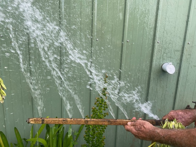 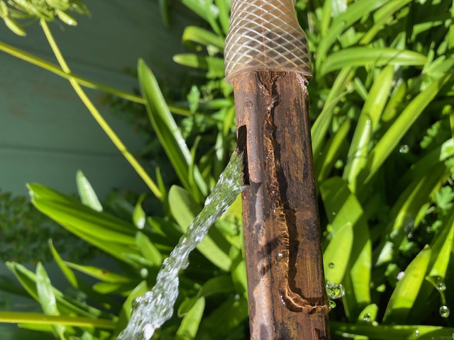 Normans data suggests Type C standard galley SLOT# 1 2 3 4 5 6 FLOW 3.87, 1.82, 1.88, 1.85, 1.82, 1.93 (gpm) LENGTH 0.900, 0.500, 0.400, 0.300, 0.300, 0.300, (in) TOTAL FLOW 13.96 GPM Modified D gallery SLOT# 1 2 3 4 5 6 FLOW 3.31, 3.08, 2.91, 3.11, 3.05, 3.70 (gpm) LENGTH 0.550, 0.500, 0.450, 0.450, 0.400, 0.400in) TOTAL FLOW 19.16 GPM I basically copied Norman but adjusted slots more in an attempt to address cylinder 2-5 getting more. It probably doesn't matter but why not if I'm at it. SLOT# 1 2 3 4 5 6 FLOW LENGTH 0.550, 0.550, 0.500, 0.500, 0.40, 0.400( in) TOTAL FLOW GPM So harping back to the first pic; I pondered slot 1 is useless for exhaust valve 1, perhaps slot 2 and 4 had merit for exhaust valve 4 and 5 due to the angle water was ejected from the galley, but overall not so good. So some brass elbows where cut and soldered on in the hope to correct the angles. This it did though I still needed to adjust them here to be more vertical. In this pic however you can see there is more water from slot 6 (left), and slot 1 (right). Its hard to tell in the pic but the water volume increased as it ran along the gallery utilising the increase in back pressure from the dead end after slot 6. My other pics don't show it but the top of spray also had an increasing angle from slot 1 to 6, so I feel I am achieving my goal of increased flow along the galley.  What I had done, though I could deflect the water more vertically I had changed it from a rather tick jet into a spray. So I mucked around with the angles and curves of the deflector tabs but in the end I concluded it's a fail.  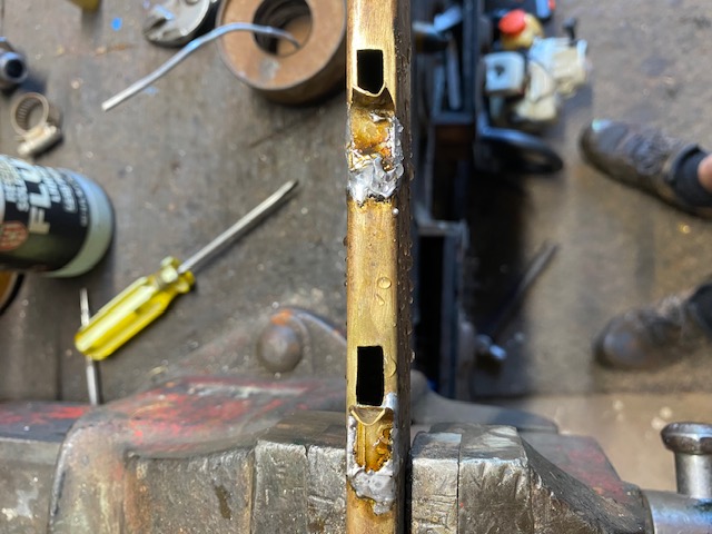 A fail because the water passing by the slots in the rest of the block would consume it easier than if it were a jet. So less effective. I suspect the jets will still be consumed but to a lesser degree. So the next instalment is remove the L shaped tabs and solder on C shaped taps to collect and corner the water into a straight exit from the galley. This should, if it matters at all, direct cooler water onto the exhaust valve casting all the way down the block. Guess I'll have to count each slot to how long it takes to fill a bucket also. . | |||
Jeff Martin Frequent User Username: jeff_r_1 Post Number: 610 Registered: 07-2018 |
Jason Any baffles you solder on aren't necessary because the coolant is flowing into coolant, not air, the dynamics of fluid flowing into fluid change when compared to fluid flowing into air (atmosphere). Like comparing apples to oranges The holes are directed at the correct location and adding any baffling may direct the flow away from where it is needed and intended. I would drop the baffling idea. The pressure in your garden hose is probably quite a bit greater then the water pump is ever going to put out, it's about volume, not pressure (the way I see it). When testing flow with a garden hose, keep the gallery level so you take the gravity factor out of the picture, turn the water on just enough to to get a gentle to medium burble of water out of the first hole (the one closest to the hose). If I'm right the burble should be all the same out of all the holes, that assumes that the drain hole at the end of the gallery doesn't rob the over-all volume too much, but it should equalize itself once the gallery fills with water. If you want more cooling at the end, then the holes have to be made larger to increase the volume of coolant to the rear exhaust valve area. The pump has to put out enough volume to accomplish this, and it probably does, but in the end, the front hole has to be made smaller to be sure this happens. An old corroded pump where the body doesn't come close to the impellor anymore will have trouble delivering volume. The way I see it, all the holes should be all the same size, why RR made them all different, does not make any sense to me, but the front hole is simply too large and the rears, still too small. The way the gallery sits from the factory for the 4.5 litre and the 4.9, it does not allow enough volume of coolant to get the the back of the engine. Here are some photos of the original gallery out of my 4.25 litre, note the holes are all the same, but any equal volume that's achieved from all the holes being the same size, is mute, because of the two round 1/2 inch holes on the side of the gallery. Much volume is lost from the holes on the side. However, the gallery is hard up against the underside of the block, so any coolant that does flow out of it does come in contact where its needed, but I believe the design is flawed over-all from those side holes. The other two galleries are not hard against the block, this allows for more coolant flow to reach a larger area, but the gallery from the 4.5 litre still has a very large hole at the front and too small at the rear, thus cutting down the volume of coolant to the rear exhaust valves. The one from IntroCar is improved; I took measurements of the holes and the surface area of the holes are similar, with #4 being the largest at 75.4mm square and the smallest on #2 at 60.3mm square. The one at the front from IntroCar is 72.07mm square, while the 4.5 litre ones' front is a whopping 124.35mm square, you can see the difference with your naked eye. The drain hole from IntroCar's is smaller too. Here's an interesting video of a Chrysler flat head six, look at its gallery, all the holes are the same size, or at least they appear to be. The water pump is also designed to pump coolant into the block as well, a much better design over-all in my opinion. At around the 20 minute mark. https://www.youtube.com/watch?v=RQNszFmHJHQ   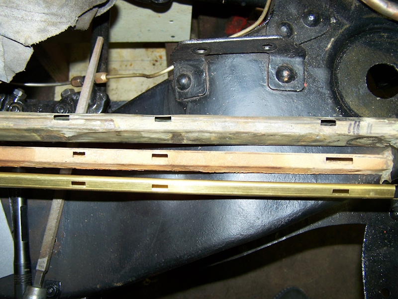 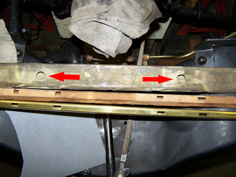 Note the 2 half inch holes in the 4.25 gallery.  Drain holes at the rear underside, the one from IntroCar is now much smaller. | |||
Jason Watson Experienced User Username: crikeydawn Post Number: 125 Registered: 07-2023 |
There is no doubt the key to all this is drive your car more and change the coolant every 2 years. This low milage caper with multiple decade old coolant does nothing but undermine perception. Are you going to rain on my simple experiment Jeff? I suppose Norman produced this 13.96 gpm for the standard galley. I have no idea what the flow of a water pump is but to file a few mm in total out of a few holes to increase it to 19.16 gpm didn't appear to eventuate in my little foray; given the same pressure was applied at 11gpm via the hose. Admittedly I didn't know what pressure it was. From today to fill a 10 lt bucket in seconds slot 1, 2, 3, 4, 5, 6 sec 75, 73, 56, 58, 55, 42   There was no doubt a solid jet of water was heading vertically instead of 45deg towards cylinder 6. And the fan type spay had been eliminated from yesterday. I agree these jets will be swept away by surrounding water flow but must have a far better chance of getting to an exhaust valve casting than before. I'm also confused if all this water is shooting out at 45deg towards exhaust valve 6, and being swept away by surrounding flow, why then is exhaust valve 6 so hot in the first place. I'm not sure I agree all slots should be the same. If you apply that to the hose then more comes out slot 6, then 5, then 4 and so on simply because the water has no where to go. The back pressure from the dead end appears to create its own pressure against what the water pump (or hose) input is regardless of its volume or pressure. Manipulating the holes to deliver equal volumes of water as it travels down the galley makes sense to me. But I'm happy to be completely misguided, I'm a pretty simple sole. My galley has a 4mm hole on the underside at the dead end, no cover however like in your pics. No doubt this is the first blockage of a silted motor. And to be honest its pretty dumb. It should be the size of slot 1. My 4.9 galley is wedged in hard against the cylinders and whatever casting on the other side. Going of Normans D galley sizing for slot 1 and 6, I have 33 seconds difference between them to equalise slots 2,3,4,5 to fill 10lt. I'd like to equalise that to roughly 68, 61.5, 55, 48.5 seconds for slots 2, 3, 4, 5 roughly. But really it probably doesn't matter. I'll fiddle with the height of the C covers to minimalise any disruption to water flowing over the top of the galley, but still maintain the vertical jets. I guess it's possible the C covers may create a small eddie behind them. I suspect drilling a small hole on the back side of the C will address that. . | |||
Jeff Martin Frequent User Username: jeff_r_1 Post Number: 612 Registered: 07-2018 |
OK, I don't think adding your baffles is going to hurt anything. All these engines survived well enough with the RR designs despite their perceived flaws because they were so overbuilt. I'm going to disagree with Norman's deduction that the large hole in the front is robbing volume from the rear holes. Notice I did not say pressure. I think even a worn pitted pump will over come the large hole and supply enough coolant to reach the rear exhaust valve area. Granted, that if the front hole was large enough, and the pump did not have the capacity to over come such a large hole, you would be in trouble. It would be interesting to set the pump up with some plumbing to see just how much water is flowing through the gallery if the pump was running at idle, lets say 600 rpm. I also believe that having the holes the same size in square area is important so all the hot areas receive an equal amount of coolant; the Introcar gallery supports this, even though they're not all exactly the same shape, but they're certainly a lot closer then the RR design in square area. Introcar did not just make up that new gallery, much testing was done to improve over the RR design. Norman also mentioned about the coolant growing warmer as it reached the rear of the gallery as it took heat away from the frontal valves, but this doesn't make sense to me. In order for it do do that, very hot coolant would have to re-enter the gallery after removing heat from the valve area at the font, but that doesn't happen. It exits the gallery to where it flows into the head's numerous holes and then reaches the thermostat. There is no reason for the coolant that is just exiting the radiator, to become hotter at the back of the gallery because it's just flowed through the massive rad. Also, in order for all this to happen successfully, the block has to be clean, even more so on the 4.5 and 4.9 litre engines because of the siamesed cylinders. A silted block would force the hot coolant to surround the gallery causing the rear of the engine to get very hot, the cracked valve seats at the back supports that. I will say this about your baffles, just soldering them on with a butt-joint may not be adequate as the heating and cooling cycles will eventually crack the solder causing your baffles to let go. I think you need to create some tabs to give some surface area so the baffles stay put. Even of they did let go, they're just going to sit in the block and not do any harm, eventually ending up at the bottom of the block. | |||
Jason Watson Experienced User Username: crikeydawn Post Number: 126 Registered: 07-2023 |
Yes the simple solution probably is, if the cooling system is clean and healthy with no silt, overheating issues don't exist. Trouble is its such a job to clean everything properly I can understand why a decent flush is hopped for as adequate. I stuck my camera down between cylinders 3 and 4, and jammed a long handle screw driver down there. Low and behold with a bit of gouging I unearthed about 3-4mm of compacted sediment. Again that is after a hot caustic bath at the motor rebuilders. Thankfully for the rest of the block the screw driver just scratched the surface. But there is also much of the block that is inaccessible. I concur the idea of the galley is to transfer cool water direct from the radiator almost insulated to some degree down to where its required. However this water then mixes with general water on a path from the front of the motor to the rear getting hotter by the inch. Again this is why I think more volume is required as you go down the galley. I guess some of that hot general water escapes through the pass between 3 and 4 cylinders, the rest is on its way to 6 before heading around the back and up the other side on its way to the front. So cylinders 4,5,6 get a poor deal really. I suspect fitting an external pipe via a Y fitting where the cylinder block drain exits the block, then re join this pipe into the system before the radiator would increase overall circulation and may well be an easy fix to some degree for silted motors. I'll plug my galley into the hose and take various low flow pics. To my mind however pressure must increase with volume as the galley is pretty much dead ended. This increase in pressure and volume compensates for increased heat as revs increase. 600 rpm will have X volume with y pressure, but 2000 rpm will produce its own figures. So still not sold on one slot suits all. My workshop manual suggest an S water pump produces 20 psi at 3200rpm, and the system holds 15.91lt or 3.5 imperial gallons. I'll have to stare at that for a while as my math is not good enough to turn that into anything useful right now. I wonder if Introcar care to share why their galley is the way it is? As for my soldering, point taken. The surface was well sanded and fluxed before soldering, but will give it some thought. | |||
Mark Aldridge Frequent User Username: mark_aldridge Post Number: 866 Registered: 10-2008 |
Jason, the external pipe idea is similar to utilising the rear heater outlet to provide a permanent water flow. I leave the demister matrix permanently on on my S1 and shut the airflow off by reversing the vacuum connections at the bulkhead. This does reduce temperatures at the back of the engine. | |||
Jason Watson Experienced User Username: crikeydawn Post Number: 127 Registered: 07-2023 |
Thanks for the input Mark. I'm new to this car but suspect your suggestion may well be practiced around the world. Would also think heating issues are common too many classic cars regardless of creed. I'm lucky enough to have brand new radiator come with this car. And determined to give it the best cooling system I can. Its hot as hot down here seeing 36 celsius in my neck of the woods, and enough humidity to feel like you just got out of the shower, well almost. Add aircon to the cars duties and its got a tuff job to perform. | |||
Jeff Martin Frequent User Username: jeff_r_1 Post Number: 613 Registered: 07-2018 |
We'll agree to disagree on some of these things Jason. I will say I believe that RR over analyzed and over designed things making something that could be simple, into a complicated mess that required huge amounts of maintenance. Lack of technology back then made things worse, like not having proper coolant with corrosion inhibitors, or how to remove impurities in the casting of the blocks. | |||
Brian Vogel Grand Master Username: guyslp Post Number: 3362 Registered: 06-2009 |
Jeff Martin wrote:
Just adding that you are definitely not the only person that feels this way. I have never seen certain more Rube Goldberg-ian ways of doing things, for no good reason, than I have on my SY cars. There are also many occasions where Crewe grossly overengineered things that didn't need it while underengineering others. Virtually any electric motor uses plastic gears being one example of underengineering where it wasn't a great idea. As a side observation regarding lack of technology "back then," it endlessly floors me how many people will insist on continuing to use technologies from "back then" when it comes to fluids and lubricants that hurts rather than helps. Modern coolants and motor oils are just vastly superior to what was available even 30 years ago. Brian | |||
Mark Aldridge Frequent User Username: mark_aldridge Post Number: 867 Registered: 10-2008 |
Jason, you are spot on with your comment that it is not only RR that have back of block/ head heat issues. I fitted a rear take off on my race Austin 7 engines to stop No.4 cylinder cooking and also on my BMC "A" series engines. In the UK 24c is a hot day ! | |||
Jason Watson Experienced User Username: crikeydawn Post Number: 128 Registered: 07-2023 |
Jeff it's a shame you're on the other side of the world, I'd bring some drinks and nibbles over and we could fill in the afternoon. Think I might be one of those over thinking it as well. Slots 1, .550 2, .550 3, .500 4, .500 5, .400 6, .400 inch Pic 1 Hose just turned on, slot 1 not doing much. Pic 2 Hose turned 1/3 turn, 1 and 6 doping a little less than 2,3,4,5 Pic 3 Hose on 1/2 turn, all the same. Perhaps 6 has a little more volume. 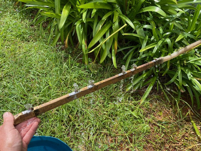 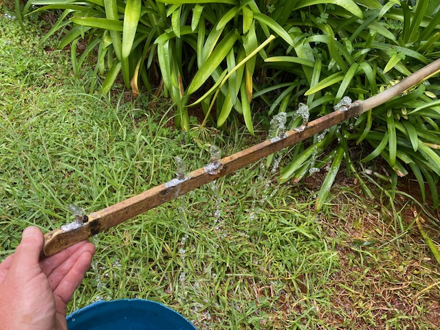  Think I'll ditch my C channels, stuff the galley back in and change the coolant every two years. | |||
Jeff Martin Frequent User Username: jeff_r_1 Post Number: 614 Registered: 07-2018 |
 Does your gallery have a large hole like the one here from the 4.5 litre engine ? (boxed in red) Also, are all the holes in your gallery all the same width ? I could see where Norman would deduce that if the first hole is too large, that it would rob flow from the rest of the gallery, and even more so at the end, but for this to happen, the water pump would have to be quite corroded where it could not put out enough volume. | |||
NormanGeeson Unregistered guest Posted From: 81.98.117.162 |
Jason Before we go further could you please advise the part number of the cylinder block you are dealing with here? Failing that, could you advise if you are dealing with a low or high (8:1) compression engine cylinder block? To clear up a point. All the slot measurements and flow figures in my article were taken from R/R's test bed figures. (Message approved by david_gore) | |||
Jason Watson Experienced User Username: crikeydawn Post Number: 129 Registered: 07-2023 |
Hi Norman, My part number is UE2018, and it has a similar moulded font on the other side T36. Rear right upper side on a machined face, BSE 463 or 4S3. How do you tell if its a low or high compression? Jeff, yes slot 1 is longer in length than the other rectangles slots by almost double. 1 to 3 are rectangle in shape, slot 4 to 6 are squarish in shape and wider than the rectangles. | |||
Jeff Martin Frequent User Username: jeff_r_1 Post Number: 615 Registered: 07-2018 |
Jason, maybe UE2018 ? 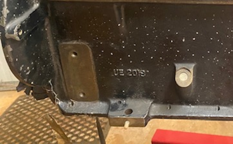 I thought that the front hole should be made smaller and that would allow at least one of the smaller holes in the back to made larger. I could give the exact dimensions of the gallery holes in the one from IntroCar to transfer over. I still believe the holes should be all the same size in square area no matter what shape they are, but you don't want to create less area over-all by making the front hole too small. If you take away in one, then you have to open up at least one other, the idea is to get more flow to the back. I'll take the square area of all the holes from the 4.5 litre block and the one from IntroCar, and post it here. I'm looking forward to what you have to say Norman. | |||
Jason Watson Experienced User Username: crikeydawn Post Number: 130 Registered: 07-2023 |
Correct Jeff EU2018, my mistake but time has passed and the site won't let me edit it. Moderator Note - have corrected the error  | |||
Jeff Martin Frequent User Username: jeff_r_1 Post Number: 616 Registered: 07-2018 |
You have half an hour to change things after posting. It's fixed well enough anyway. Jeff - now fixed completely David | |||
Jason Watson Experienced User Username: crikeydawn Post Number: 131 Registered: 07-2023 |
Right, thought if only volume matters I'll have a tinker before whatever the next step is. I ground my C channels down to 5mm high. Drilled a hole at the 5lt mark in a 10lt bucket. Measured a flow rate of 16sec - 3.5 GMP to fill 5lt before flowing out the hole, then plugged my galley on. It looked like this. In hind sight I should have tried 7 or 9mm on the C channels first. They would easily fit into the block and most likely retain the vertical jet. You can see at 5mm they are tilting towards the rear again. Interestingly my pressure is far higher at home than where 11gmp was tested, but my tap opened fully and all I could muster was about half as hight in comparison. 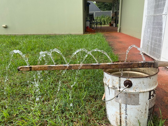 My slots in Sq mm 1, 69.19 2, 77.71 3, 74.82 4, 71.07 5, 81.29 6 76.98 seconds to fill 5lt at 16lpm or 3.5gpm 1, 152 2, 146 3, 99 4, 94 5, 88 6, 60 So make of that what you will. | |||
Jeff Martin Frequent User Username: jeff_r_1 Post Number: 617 Registered: 07-2018 |
What appears to be happening is the rear pressure is higher because it builds at the back of the gallery because it has no where else to go except out the last hole forcing more water out it. Because of this, the water in the first hole takes longer to fill the bucket, and your numbers in seconds shows a sequential rate, although not at an even rate. If all the holes were the same shape and the same size in square area, I would expect that the difference in seconds between your numbers would be the same or very close. Even now they're at 5 to 6 seconds, with the exception of 2 and 3 at 47 seconds and 5 and 6 28 seconds. It would be very interesting to do the same test with the actual pump at an idle of 600rpm, taking in account that the pump would be at a higher RPM because of its smaller pulley. There should be enough back pressure on the pump, and as a result of that, more flow of water should be coming out the rear holes. This has been demonstrated here with your garden hose test. This assumes that there would be enough pressure built up by the pump to achieve this, although not on a level here from the pressure coming from the garden hose. The holes on your gallery are all about the same size in square area, I would just leave it alone the way it is. About the water (coolant) getting hotter at the end of the gallery, I don't agree with this. The surrounding hot water after it exits the gallery would have to heat the water in the gallery itself for this to happen, and why only at the back end ? There is always a constant flow of cooled water from the rad/pump to fill the gallery, the surrounding heated water out side the gallery can't possibly affect the cooled water inside the gallery enough to even matter as long as there is a place for the hot water to go after its done its job of taking the heat away from the exhaust area. The heated outside coolant may heat the gallery some, but it would be so very little, I don't think it would make any difference. Now, if the block was all silted up at the back, then yes, the heated water would have no where to go and thus, the rear of the block would certainly get hot, so much so that the seats would crack. All this is worsened from 5 and 6 cylinders being attached together and even the gallery itself may be full of silt blocking off the rear coolant holes. It will always be worse at the back because the silt is pumped to the back of the engine through the gallery. I would not even add your baffles. RR put the gallery at an angle to direct the coolant in a given direction, adding your baffles may effect that design and create an unwanted effect. Coolant behaves differently when flowing into coolant, what you see when coolant is shooting out into the air is going to be much different than what is happening inside the block when the gallery is totally immersed in coolant. | |||
Jason Watson Experienced User Username: crikeydawn Post Number: 132 Registered: 07-2023 |
Yes I wondered if the angle on the galley played a role. From my observations if the angle is there to shoot water off to the side, then it's a fail as water doesn't come out in any side ways direction. Just up and rearward if the gallery is positioned horizontal and vertically. Think it faces the wrong way to the valves anyway. Think you're right if the C sections are left on at 5mm, it appears to be no benefit to them. Shame I had a rush of blood and cut them down so far. I should get some more brass plate to have another crack, but understand they may produce a negative side effect. Knowing decent coolant, a clean motor, and improved slots will sort the problem I'm loosing interest. I need to clarify as I didn't mention it, slots in post 131 are not the same as 128 anymore. I played with them a little to increase flow as water heads towards the end of the galley. Yes I agree temperature of water would not increase as it travels down the galley, just as it pops out it joins ever increasing temperature wise water making its way down the block on the outside of the galley. Also think it's why flow rates of slot 1 and 2 produce much lower volumes. By design or fluke, the cool water just left the radiator flowing past the cylinder and exhaust valves 1 and 2, is just cooler all round so needs less attention. Now I know the psi of the pump at 3200rpm I have been asked to measure the outlet area of the pump, or where it enters the block. Then the flow should be able to be calculated, and potentially scaled down to 600rpm? Beyond me but will send it to the FIL engineer. Been thinking for the soles with a silted motors that do not wish to pull it out, but happy enough to remove side plates, radiators, water water pumps etc. Below is a 6mm OD copper tube with a push on air line fitting. Compressed air along with the hose should have some success. Perhaps thereafter some prodding with 3mm fencing wire with a small hook on the end may be worth try. The wire would be an attempt to clear the small drain hole at the end. Same process down the side plates may giddy up the silt.   I'd like to say after a few acids have been used but I'm dealing with a disassembled block, not one in motion. So would need to check acids on metals or seals. Will have to get around to seeing if a cleaning/sludge one first then a rust/scale one second has the results hoped for. | |||
Jason Watson Experienced User Username: crikeydawn Post Number: 133 Registered: 07-2023 |
So today measuring the out put area of the pump, or more so restriction point it has to flow though, I found some points of interest for what its worth. Galley and location in the block, to the size of the hole in the water pump housing means the lions share of water goes into the galley. 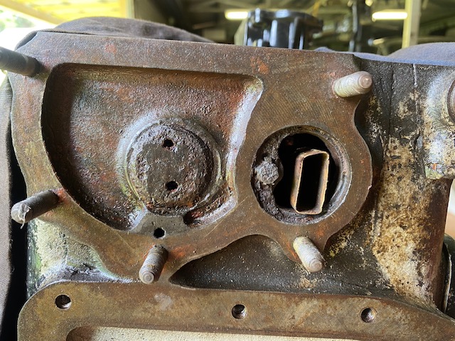   If the exhaust valves are off the upper right than I'm not surprised they get warm. Whats strange to me and hopefully someone can explain it, is the big half moon shape part of the water housing fits over two small holes just above and off to the right of the centre lower stud of top pic. Those bad boys flow through to matching holes in a cover plate on the other side of the housing which the water pump bolts. Small holes from the block, into big cavity, then small holes to where all the volume is created. I don't get it.  Furthermore for what its worth while its all apart, think some porting wont hurt. For some reason in the middle of the oval slot casting, which is the path water form the pump takes to the block, there is a 1-2mm sharp edge. Reckon by removing it flow will be improved as the resistance would be removed. The areas of the oval is 568.5sq mm, it may be down to 550sq mm with the casting ridge in the middle of it.  Perhaps trivial but also 5 minutes work while it's apart. Jeff the FIL's tech books didn't have tables for the type of pump it is. They were all for other industrial types of pumps. He has some math we will work on tomorrow regarding the size of the impeller blades on the pump. | |||
Richard Gray New User Username: mooney1el Post Number: 35 Registered: 08-2016 |
I notice in your photos and testing that you do not show the gallery plate, UE524. I believe that this plate is a necessary part of the water distribution system since it forces cooled water into the gallery. The plate is available from Kelly Opfer at British Tool Works; https://www.britishtoolworks.com/product-page/sc-water-galley-plate-104-thick-ue524.
| |||
Jason Watson Experienced User Username: crikeydawn Post Number: 134 Registered: 07-2023 |
Good point Richard, thank you. I have not seen this as my motor is in various boxes yet to be sorted, as I'm not really at that stage yet. I have just noticed a pic from yesterday I thought uploaded is not there. You can see here without the plate, the galleys lions share I was talking about. I thought in reflection I was mistaken. If you look at the lower half of the oval casting, the bit midway that fills the lower 1/3 of the hole drops away on the other side. It's as if the pic makes it look like it blocks any water under the galley. However looking at the galley in the block pic of previous post there is little flow under it anyway. But wow if you add plate EU524 there is none! 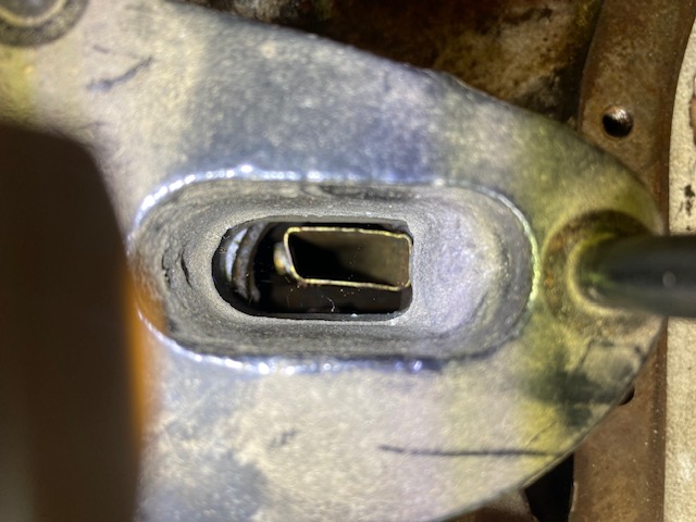 Plate EU524 looks like there is no option for water to go anywhere but into the galley. The whole flow of the water pump and the rest of the block is conducted via the galley. Is that what you are saying Richard? If that is true I fluked my hose on the galley dealings. Looking at my blocks casting pic previous post it seems I have the bolt to hold plate EU524, but the grime suggests it has not been there for some time and sure wasn't removed in the pulling down of this motor. I wonder if the plate had been removed in an attempt to increase volume for a silting motor? If I look at my casting there is a foot print of the blocks casting that suggests it may have been that way for some time. The motor had around 100K on it according to the speedo. My bet is this motor is not on its 3rd rebuild so removal of plate is possible. I will measure the old pistons to see if they were standard.  The plot thickens however looking at the parts manual. Ref 1 is for RE20949 water galley. If you take that image the galley has a blocked end with a small hole, and furthermore has a locating screw accompanying the plate which fills that hole, the only hole left in the galley. RE20949 looks to be a cover that slides over the galley protruding from the block. So where is the part number for that. Then it gets even more confusing as the locating holes in the plate are off set to the centralised one in the blocked coverer with no flow. What am I missing.  | |||
Richard Gray New User Username: mooney1el Post Number: 36 Registered: 08-2016 |
Jason - I believe that RE20929 is the part number for the gallery itself. The squiggly line that makes it look like two pieces is used to show that the part continues rearward until it changes shape at the end to accommodate the spigot there. That change in shape is depicted in the drawing. There is a small hole in the plate that allows some controlled water flow around the gallery itself. I am not an expert in this area at all, I am however familiar with Norman Geeson's work regarding these galleries in their various configurations. It was he who pointed out the lack of these plates on another thread on the US RROC Forum. In one thread Norman suggested that the plate I referred to must be soldered to the gallery. That is difficult to do since the gallery is removed from the rear and the plate would have to be soldered in situ. It is doable however as a friend of mine has recently done so on his Cloud. Indeed, it was from Norman's observation that prompted my friend Curran Stone to contact Kelly Opfer to have him produce these plates and make them available. The plates for the earlier MK Vi's were of a different thickness and slight configuration thus two part numbers are available. Kelly obtained the original drawings to make the parts he provides for sale. Also, above Jeff provides a link to one or more of Norman's articles concerning the water flow and the issues that the engineers faced. | |||
Richard Gray New User Username: mooney1el Post Number: 37 Registered: 08-2016 |
Here is a quote from Norman's article. "TYPE D GALLERY ASSEMBLY This RE 20949 assembly was introduced for the 4.9 Litre cylinder blocks. It comprised of a RE 20946 rear end cap or spigot, a RE 20947 gallery and a UE 524 front end plate. These parts are shown in Fig 7B and 7C. A drain hole 0.125 diameter is drilled in the gallery base some 1.450 from the rear. The rear end of the gallery was located into a spigoted RE 20948 rear cylinder block closure plate and secured with a counter sunk screw which passes through the block closure plate and screws into the gallery rear end cap. The gallery is firmly secured and located against the rear block plate and reference to Fig 7A shows that it is longer than the other gallery types. The advantage with this design is that the gallery is positively restrained from moving rearwards by the spigot location into the rear block plate and does not rely on any front end tabs. The front of the brass gallery passes through the UE 524 front end cap and does not have any front end tabs. In this case, easy renewal of a corroded front plate is therefore achievable. Reference to the centre bottom of Fig 7C, shows that the gallery cross section changes from rectangular to circular at the rear end. This circular rear section will not pass forward through the cylinder block and extraction of the actual gallery assembly necessitates removing the engine. My previous comment regarding fitting a brass front plate and retaining screw would also appear to be appropriate for this type of gallery assembly, as would be the requirement to be aware of the original front plate corroding. " https://kda132.com/wp-content/uploads/2018/04/Cylinder-Blocks.pdf | |||
Jeff Martin Frequent User Username: jeff_r_1 Post Number: 618 Registered: 07-2018 |
 The 2 holes holes in the back plate and the one into the block where the aluminum housing bolts on are drain holes. The green area shows the notch where it meets up to the drain hole in the block. The red aero shows a point of decay in the aluminum where leaks can occur down the stud, around the threads and out through the lock washer. I had mine welded up so I could put things back to spec. There's very little material here for the gasket to bite into, poor design in my opinion. I suppose one could use JB-Weld here, but it's a pretty easy fix for someone who has experience welding aluminum.  The small bolt (or set screw) pointed out in red, holds the adapter plate in from Kelly, Norman makes mention of this in his article and comments that it usually comes out with no problems, but I would be careful here _ a little heat and penetrating oil here goes a long way. I would replace it with a stainless steel screw. Brass would work well enough, but brass twists off easily and will be a problem for the next guy who works on your engine. The small hole in the plate is for a locking tab; I don't believe RR intended any coolant to flow through this hole directly into the block. I think 100% of the coolant was meant to flow directly into the gallery. However, as the hole is so small, that it would make very little difference, when you start cleaning up in there, you may find that the locking tab hole may not even be drilled through. Take note that the locking tab on my 4.5 litre engine is stainless steel. As your engine sits now with the missing plate, very little flow from the pump would enter into the gallery, there in which lies the over heating problem when the plate rusts away. About the water galley ports angled away from the valve area. Coolant would flow towards the top of the bore in that area and then be directed back towards the exhaust valves _ the way I see it; but given the fact that all the coolant from the pump is directed down the gallery, there's going to plenty of flow and pressure to cool the whole area where the most heat is produced, including the exhaust valve area. https://www.britishtoolworks.com/product-page/sc-water-galley-plate-104-thick-ue524 | |||
Jason Watson Experienced User Username: crikeydawn Post Number: 136 Registered: 07-2023 |
Thanks for the 101 on reading drawings that now makes sense. My galley has the rectangle end flared into a round cap. So though a 4.9 type D, doesn't appear match the drawings or part number. It gets sandwiched between the cylinder and block casting to stop it going forward, and the inspection plate on the back of the block to stop it going backward. Not sure why it has a retaining screw through the plate but there is. After staring at stuff today I think I'm almost convinced to add a tap at the end of the gallery through the retaining screw's location. Can anyone tell me the distance between the block and firewall please for an S or Cloud. Changing coolant every few years is one thing to say, but another to be practiced. The motor may not silt up again in my time but for the next custodian it may well do pending conditions. So it's easier to open a tap and give the gallery a quick flush after checking the oil. Have started making the brass plate UE524. Did my porting also on the water channel through the housing, smooth as now. Jeff, I need to have a foot welded onto the alloy thermostat housing. It's broken off for some reason. Will have a look at doing that drain then also. Do you think there is merit to move that drain a little to the side. Directly above a steel stud is just asking for trouble and will address the gasket thinness you brought to attention. | |||
Jeff Martin Frequent User Username: jeff_r_1 Post Number: 619 Registered: 07-2018 |
A used one is fairly inexpensive. https://www.flyingspares.com/thermostat-cover-outlet-ue2640u.html | |||
Jason Watson Experienced User Username: crikeydawn Post Number: 137 Registered: 07-2023 |
Goes like this Jeff The upside to knocking around with the FIL � father in law� is his generation challenges mine. I say I�ll just buy it and he goes ahh�. lets have a look. I�m grateful he has shed full of off cuts and saved bits of you name it? Then there are the tools and machinery, plus the knowledge where to put your finger on what�s required. From the link sent, thank you Richard and Jeff . I say the plate is $40 so I�ll just buy it. He said is that Sterling or US, either way its too much and then add freight. I can see his point as this little 41 x 2.6mm thick bit of brass is somewhere between $80 to $130 landed. We jump onto RREC, EC for enthusiast�s club and log into the hunting house I think he called it. Pull up the drawing for the plate and make a copy. Wander out to the shed, find ourselves a bit of appropriate brass plate, and scribe it up. He says you can do that one. The guys a one stop wonder. Then he says, if it were mine, think a tap at the end of the gallery would be useful. Let's run though the �what if� questions. So all sorts of Qs about working, not working, upside, down side, athletics and so on. He then pulls a tin of brass fitting off the shelf and produces a tap to match the period. I just looked at him and said "Whatever is rightly done, however humble, is noble" So if alloy was not so difficult to weld, we�d probably have a crack with the MIG we bought to learn on. I�ll outsource the welding as its 2 minutes up the road, but imagine a lesson on the milling machine or just good old files will be in order to shape it like nothing ever happened. The nice bit is he is learning as am I. His gig is Silver Ghosts and Phantoms where he had to put his skills to work because the bit didn't exist. He finds the S an intriguing bit of kit both good and bad. He once owned a MkVI that got hot, he now better understands why. I understand why his skills have been disbanded for convenience and profits, just I think I prefer his generations way of doing it. I'm lucky as I have the time to spend with this amazing man. | |||
Jeff Martin Frequent User Username: jeff_r_1 Post Number: 620 Registered: 07-2018 |
Sometimes it can be tricky to weld up that crappy alloy they used in those days, there were a lot of impurities in them, plus dirt that made getting a clean weld almost impossible. That thermostat cover didn't seem like too much at around 52.00 OZ dollars, but yeah shipping. After owning my car for around 30 years, I've become accustom to paying more, like 500 bucks Canadian for a new water gallery. I could make one, but I just have better things to do, even now it's taking much work adapting that new gallery to a 4.25 litre engine _ I'll post photos of what I had to do. I'll also post what my water pump adapter looks like. Yes, I suppose one could elongate the hole in the block so the notch in the cover can be moved up. They're just drain holes. If you want to leave it, the aluminum in that area has to be totally in tact to get as much surface area as possible. Mine never leaked through all those years that I've had it, although it was leaking in a different area. | |||
Jeff Martin Frequent User Username: jeff_r_1 Post Number: 622 Registered: 07-2018 |
 This is the space between the drain hole and stud after it's been filled in with aluminum and some JB-Weld. Even after that, that area is quite narrow, but it has never leaked there. I suppose the original drain hole in the block can be blocked with a threaded plug as I did and re drilled higher up, this off course would require adding aluminum to the adapter to accomidate the new hole.  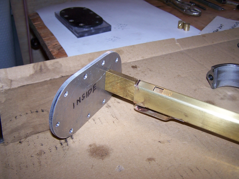 New adapter added at rear as well as a new cover to accommodate the new water gallery from IntroCar.   Front adapter; this was a lot of work making this. I'll probably silver solder it in place and just get rid of the tabs. It looks like the adapter doesn't fit very well, but it's about 1/2 thick and fits tight at the back. Jason, I would not bother adding a drain tap at the back of the engine, once the block is clean and with the use of modern coolants, the silting up problem is not existent. Mine was clear after 21 thousand miles even with some silt at the bottom of the block. The block scale in your photos has to be taken care of though _ we discussed this earlier about how to deal with that. | |||
Jason Watson Experienced User Username: crikeydawn Post Number: 138 Registered: 07-2023 |
Na... the cynic in me niggles They say with modern cars every 2 years is the coolant service life, but how many actually see it. New age 5 year service life coolant has even less chance of being changed I feel. I think people look an if its green that will do. Car enthusiast are meant to pay more attention or have greater appreciation, but why are the so many cars in the state they are. Coolant has been around from when the cars were built. The plan is this car will pay for itself to keep it moving, but also share its joy with with couples enjoying my area for the weekend. Who knows if it ends up remaining in the family, or interest drops away, or it becomes a shed warmer. I think a tap is a small detail like the JB Weld you have done to fill divots in your adapter housing. Thank you as I need a bit of that too. I guess RR-B may have earned the name as the greatest car in the world. That however does not capture perfect. I like the spacer but that's is all it is. Given where you're at, there is an opportunity to make a simple non intrusive improvement of a full sized sleeve that ends in a tap, especially as you have made an end plate anyway. Problem solved today, problem solved for tomorrow. On another note, interesting to see you have 1 drain hole, the 4.9 has two holes. Both holes flow through to the water pump just via a chamber. | |||
Jeff Martin Frequent User Username: jeff_r_1 Post Number: 623 Registered: 07-2018 |
There's no room on the Mark VI to add a tap. One would have to install an elbow, a pipe and mount the tap else where. I'm not sure even an elbow would fit, There's enough room to get my hand in there and not much more. Adding things like that just creates a place for leaks to happen where it's impossible to get at without tearing the whole car apart. I just want to worry about getting a good gasket seal and nothing else. EDIT: I have two holes as well in the division plate right behind the impellor. They were all the same in that regard. | |||
Jason Watson Experienced User Username: crikeydawn Post Number: 139 Registered: 07-2023 |
yes distance from block to firewall is a measurement I am seeking before commencement. So you like JB Weld for those little jobs. I looked into some aviation equivalents but reading the JB spec sheet it looks on par for a far better price. I found these lumps of grey hard stuff in my gallery, 4 in total. No idea what they are but they were hard like cement, not crumbly like the brown dirt stuff. Either way I hope that is not liquid metal come a drift from somewhere. Can't see any trace of it.  | |||
Jeff Martin Frequent User Username: jeff_r_1 Post Number: 624 Registered: 07-2018 |
I think it's just crap that ended up in the gallery when the engine was descaled, or it was already in there and their descaling process didn't remove it and realistically, how could it ? The gallery should have been removed along with the back cover when it was cleaned, and dealt with then as a separate entity. | |||
Jason Watson Experienced User Username: crikeydawn Post Number: 140 Registered: 07-2023 |
Agree yes it should have been removed, but when I pulled the cover plate off I broke the seal. That is the second pile after I banged it on the bench and poked some wire down it. This is what fell out when I just turned it upside down to start with. You can see another grey chunk or two in there also. So thinking about it now I don't think its liquid metal. You can also see how just a water flush won't cut the mustard, the silt is like a greasy dirt made up for decomposing rust and whatever else. I plan to run a sock in a radiator hose for the first couple hundred kilometres when its back together. I think no matter what one does to get all the junk out of the block in one action, it's a big call. 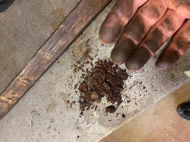 | |||
Jeff Martin Frequent User Username: jeff_r_1 Post Number: 625 Registered: 07-2018 |
Muriatic acid for the block _ 10 to 15% _ use lots of heavy grease for the machined surfaces and do it outside of course, usually in the dirt and far away from all things. Take a magnet to the gray chunks, the last time I checked, a magnet does not stick to metal. There will be chunks of iron in debris piles like that. The sock thing can be useful. Don't over think it all of this. | |||
Jason Watson Experienced User Username: crikeydawn Post Number: 141 Registered: 07-2023 |
haha I think we have gone past that mate. Never-mind, I find all this fun and educational to be honest. I'm off to Nth of here for the weekend. Promise I won't think at all. haha  | |||
Jeff Martin Frequent User Username: jeff_r_1 Post Number: 626 Registered: 07-2018 |
What a Beautiful beach ! The closest thing we have to that is "Long Beach", but it's cold, even in the summer. Very wavy and choppy too, I can't swim in it, but the surfers sure go for it ! | |||
Jason Watson Experienced User Username: crikeydawn Post Number: 142 Registered: 07-2023 |
Yep, pretty lucky we have 4 major islands with varying degrees of human encroachment at a stones throw from home. Hit any of therm midweek or out of holidays and you will virtually have it to yourself. An hour west and theirs plenty bush walks from 1 hour to multiple days. Over or under water falls and down creeks to sleeping in caves or on peaks. All good stuff when the kids were young, now they are in high school and too cool for the parents. Why I bought the Bentley to rebuild. | |||
NormanGeeson Unregistered guest Posted From: 81.98.117.162 |
Jason Health issues have prevented me keeping up, so one or two points. A UE 2018 is known as a �bulged port� cylinder block. With the exception of four Silver Wraith engines, all 8:1 compression engines had UE 2018 blocks. These blocks had exhaust ports cast such that extra cooling water passed around the exhaust valve area. They were successful at preventing overheating providing the cooling system was flushed at appropriate intervals, say every 24 months. Obviously to attain the 8:1 CR the correct cylinder head required fitting. I would say the bulge porting maybe the reason that your cooling rail shoots the coolant out at an angle and it would be unwise to alter the gallery except, perhaps, to shorten the front slot. The two gallery side holes, on earlier coolant galleries, are to direct coolant to the jointed (siamesed) exhaust ports of number 2 and 3 cylinders and 4 and 5 cylinders. No mention has been made of the fact that the rear end of the gallery fitted into UE 2018 blocks is attached by a screw through the back plate. This was done in the main to prevent any fore and aft shunting of the gallery as the block expanded and contracted lengthways. The next item is one I believe you may have been warned about but possibly chose to ignore, but if you do it will cost you big time. That is the sleeving of the nose bearing position on the axle pinion. Sleeving of shafts is quite acceptable up to a point. However, I can tell you not in this instance, and that advice comes from rebuilding those axles for over forty countries. There is not enough diameter after machining the 27 mm stub end to sufficiently get a grip. What happened is the sleeve moves rearwards until it contacts the inside of the Crown Wheel where metal is shaved off (read scraps bearings) until the remaining sleeve is tipped downwards and drops between the Crown Wheel and Pinion. At that point you have no Crown Wheel, no bearings, no centre case, and a main case with a distorted nose bearing housing. Plenty of scrap, but no axle, and if it breaks an half shaft�.no money. (Message approved by david_gore) | |||
Jason Watson Experienced User Username: crikeydawn Post Number: 143 Registered: 07-2023 |
Hi Norman, I sincerely hope you get the better of your health issues. I know others who are struggling and it's a significant frustration. This world of knowledge and predictability we have strived to build often fails with conclusive advice on outcomes. So what ever you have may the better side of life prevail. I have already modified my 4.9 gallery based on your article plus some. Time will tell I guess but it now has increasing volumes of water per slot as it travels to the end of the gallery using the same pressure. My simplistic reasoning of water is travelling down a block sandwiched between two walls, and has a front, mid, and rear point to turn around. Then along that path it gets hotter and hotter as it passes cylinder after cylinder. With the only path for cooled water to enter/travel is via a gallery ejecting it. By increasing cooler water volume as it passes each piston makes sense to me, not just more per slot than before. Ejecting it vertically straight onto the exhaust valve made sense to me also. But in refection the valves are offset to the rear of the slots, so to have it come out on 30 ish degree still works for me. Jeff made the point the water around the slots will sweep away the jet. But given ALL the water is fed into the block via the gallery I'm not so sure anymore. The out bound pressure from the slots will dominate the steady generalised flow around the block I feel. To be honest if thing blows up it will be disappointing. Very disappointing. But in the back of my mind these cars sadly they are worth little, and its likely to be working car so expanses are claimable. I understand the car was original, so the head should be the one that Bentley supplied. I have read somewhere the multiple heads for various blocks, but as the parts for these cars are priced at what they are, I figured it will run with what came with it. The inspection plate on the rear of the motor, what a place to put it. I am waiting to find the distance from the block to the fire wall on an S. So simple but yet so hard. My gallery slides in like a well fitted glove. The flared end fits against cylinder 6. I did presume the inspection plate sandwiched it there and keeps it in cheque. But can see by fastening it to the plate will make sure of it. You may have read if the space between the block and firewall is great enough, I am fitting a period tap to allow flushing of the gallery. Maybe pointless, may just what it needs on a regular basis. It can only complement the lower block drain I feel. For those not aware, this bit is for another thread. So stop reading if you are following block flushes. I did take your warning on my pinion nose, thank you. I had almost convinced myself to drop the $6000 on a replacement crown and pinion. However after talking to two engineers, and the only diff lapping shop in the country who has 40 years in the game. The united advice was it will be ok. The sleeving advise was also preferred to filling and grinding. I also considered these are not big kilometre, big horse power, big load carrying cars, and being an auto not big stress or shock loading either. Again if it does fail and the warning rings true it will be very disappointing. But I will then seek a 5k second hand diff and check the crown and pinion to rebuild, however at present the pinion sleeve cost $140. And done at a shop of many years of service on all sorts of cars from race to old RR-B. If I had carefree money I could drop the 20K required to import a rebuilt one, but that would be 25% of a near perfect car on a good day. I'm not here to disprove or challenge you Norman, or anyone for that matter. However I'm not your typical RR-B owner I imagine, rather quite the opposite. As I have said I don't have the budget and if I did I don't want a car that cost 3 times its worth to rebuild. I do however want a dam good car I can drive regularly and is a fair and worthy representation. I'm guessing half the cars in clubs have fixes that are well kept secrets. That's ok but not really in me. Tank care Norman, I appreciate your input as I'm sure many others do also. | |||
Jeff Martin Frequent User Username: jeff_r_1 Post Number: 627 Registered: 07-2018 |
Hello Norman You got me curious to see if the exhaust ports are actually siamesed at number 2 and 3 cylinders and 4 and 5 cylinders on my block as it is an early type with the threaded centre casting plug on the carbureted side. Here's a photo of the only number I could find on it, but doesn't seem to be a part number. B494C ??? 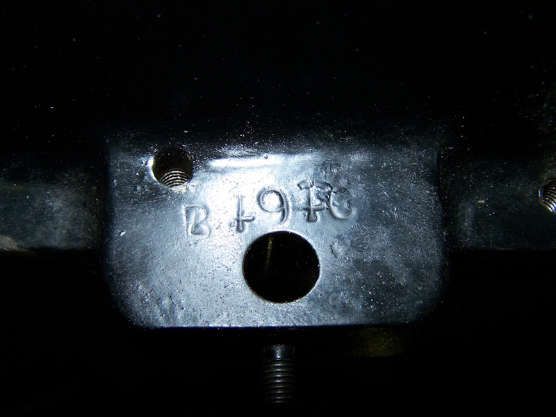 And the two exhaust ports at 2/3 and 4/5. 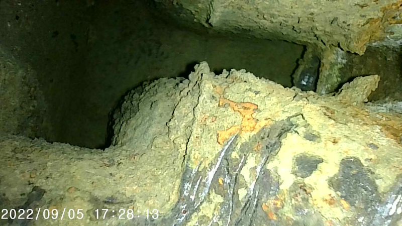 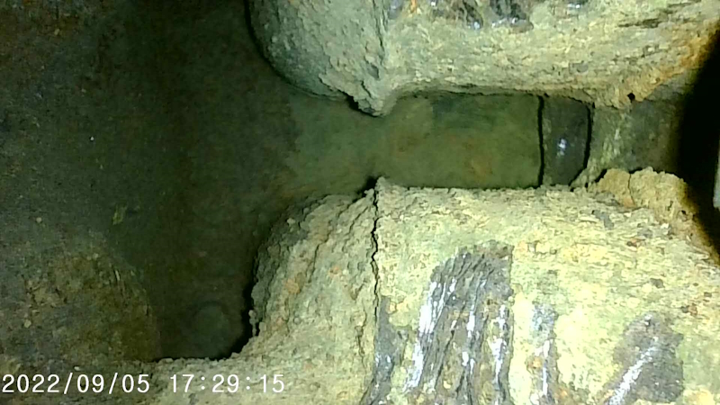 I don't know what blocks where the ports were siamesed together, but not this one _ and that's a good thing because of the water gallery I'm using from Introcar. I guess the RR engineers thought that this area would need those side coolant ports here, but I believe them to be wrong. I tried to get the camera on the 4.5 litre block I have, but the coolant passages are too small to get the camera in, plus it's so cocked up with rust, that there's nothing to see anyway. Given the fact that, that area was so choked with scale, and the owner continued to drive the car with no signs of over heating on that area, would indicate that this place between the exhaust ports was not really a high source of heat. | |||
Martin Webster Experienced User Username: martin_webster Post Number: 54 Registered: 09-2018 |
Jeff, B494C is the engine number and was fitted to chassis number B487CD delivered in July 1948. The car was originally dual blue. Martin | |||
Jeff Martin Frequent User Username: jeff_r_1 Post Number: 628 Registered: 07-2018 |
I wonder what happened to my engine, and why it was changed out ? The chassis number of my car is B297LH. Martin, where would I find the part number on this block ? | |||
Martin Webster Experienced User Username: martin_webster Post Number: 55 Registered: 09-2018 |
I have looked as far as is possible at my cylinder block Jeff but I can only find the engine serial number. I have also trawled through the workshop and service manuals and of course the parts manual but with no success unfortunately. Perhaps NG or CC can help you. B297LH delivered in July 1951 originally had engine number B348L fitted which would have had virtually all the service upgrades incorporated. It�s very interesting that a previous owner fitted an earlier engine for some reason. Martin |