| Author | Message | ||
Alexander Lynch New User Username: lex_lynch Post Number: 18 Registered: 07-2020 |
MK V1 B111 JN I am looking for any advice for the correct adjustment of the clutch fingers in the absence of having a Borg and Beck Gauge. I have considered getting some square tool steel ground to size .327 - .330 as spacers, any insights would be appreciated. 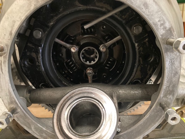 | ||
Jeff Martin Frequent User Username: jeff_r_1 Post Number: 316 Registered: 07-2018 |
It will be interesting to see what others have to say. I've never adjusted mine, I had the clutch rebuilt locally and I just installed it, I assumed the jobber that did it, adjusted it when he rebuilt it, and it's been in there for 20 years, and shifting nicely, so he must have done something right. The trans is still out of mine, soon to go back in. | ||
Bill Vatter Experienced User Username: bill_vatter Post Number: 146 Registered: 09-2004 |
It's not that difficult to make your own tool. You need solid metal spacers the appropriate thickness (each spacer excactly the same thickness) spaced around a flywheel friction plate that has been ground perfectly flat. The pressure plate cover is then bolted to the flywheel pinching the spacers such that the pressure plate is held exactly surface-parallel to the flywheel and the correct distance separating the two. Then you need a jig to measure the distance between the flywheel surface and the top of the three domed adjusting screws. The screws are adjusted to the specified distance, and that distance must be exactly the same for each release lever. The domes on each screw must not have any worn spots which would make accurately adjusting them virtually impossible Have the flywheel plate flat on the bench so everything stays in place while you are bolting it together for the measurement. The result is the pressure plate moves away exactly parallel to the flywheel. That way, irregularities in the lined driven plate don't catch in tight spots between the flywheel and pressure plate when it is slipping. You can't avoid irregularities in the driven plate so you must not have any variation in the distance between pressure plate and flywheel creating tight spots. |