| Author | Message | ||
Jeff Martin Experienced User Username: jeff_r_1 Post Number: 182 Registered: 07-2018 |
Here are some photos of what mine looks like, looks OK _ I think it's the original one in there and not the new one from Introcar. The fact that it isn't cracked or damaged in any way just from a visual inspection, I don't think it's the cause from the "grinding" into fourth gear, if anything, the amount of dirt in the transmission is the cause _ for now. The synchro & cone on fourth gear looks good too, just very dirty. At any rate, even if the thrust washer was damaged, it's no where near the fourth gear, I don't see how it could possibly effect the proper shifting of fourth gear. 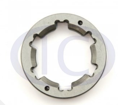 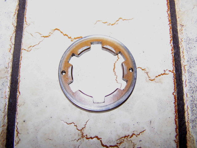 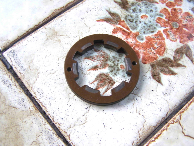 | ||
ChristopherCarnley Unregistered guest Posted From: 159.242.227.73 |
This is an original .175" thrust washer. When they break up, the whole of the 3rd speed gear and bearing sleeve detaches and jams the synchros, 4th speed included. Cracks start at the sharp inner corners of the splines. When reassembled on the 3rd motion (main) shaft, there should only be a .002" to .003" gap between the adjusting washer and the shoulder on the shaft, as excessive play leads to the cracking. What is the condition of the sliding piece and does it engage easily into the 1st motion dog teeth? Show pictures of the synchro plates, please. Christopher has sent me the images relating to this post - I will post these shortly (Message approved by david_gore) | ||
Jeff Martin Experienced User Username: jeff_r_1 Post Number: 184 Registered: 07-2018 |
There is 1 to 2 thou clearance between the thrust washer and the shoulder on the shaft, so that's fine, that would explain why the thrust washer is still intact. It can be made to slide into first motion dog teeth if you're careful, leaving a definite pause into neutral before going into fourth. If you put pressure on the synchro in then forcefully put it in fourth, it shifts fine, it's when you shift normally that the dog teeth grind. I read in the service book that the synchro's should not wedge themselves on the cones like what my video shows and that polishing the cones is permissible to keep the synchro's from doing just that. I'll have to initially use a very fine stone to get rid of the grooves on the cone left from the synchro. Flying Spares has one first motion shaft left if I can't correct the problem. At least it's not excessively expensive at around �700.00. https://youtu.be/_3WVpYshoeE Edited by Moderator to include active video link. . | ||
David Gore Moderator Username: david_gore Post Number: 3875 Registered: 04-2003 |
Images supplied by Christopher Carnley for post above: 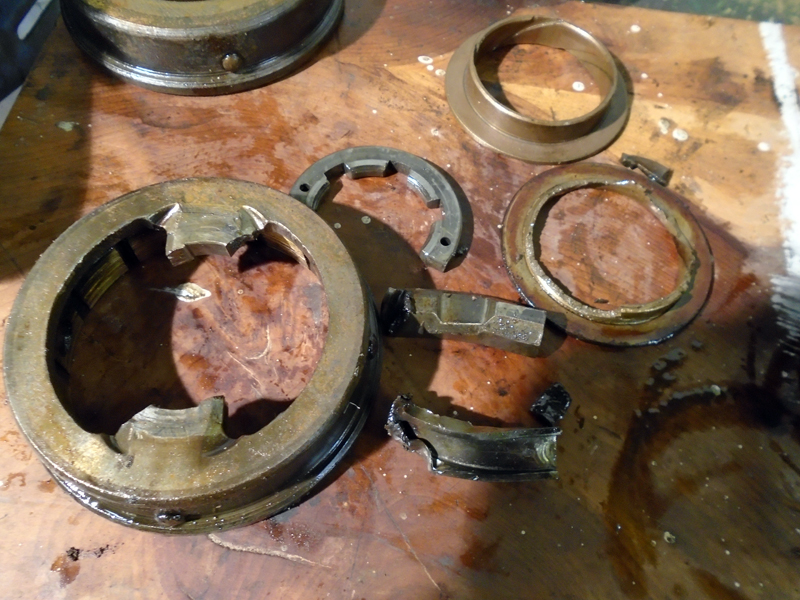 1: This shows what happens when the rear round shouldered bearing breaks its snap ring.. 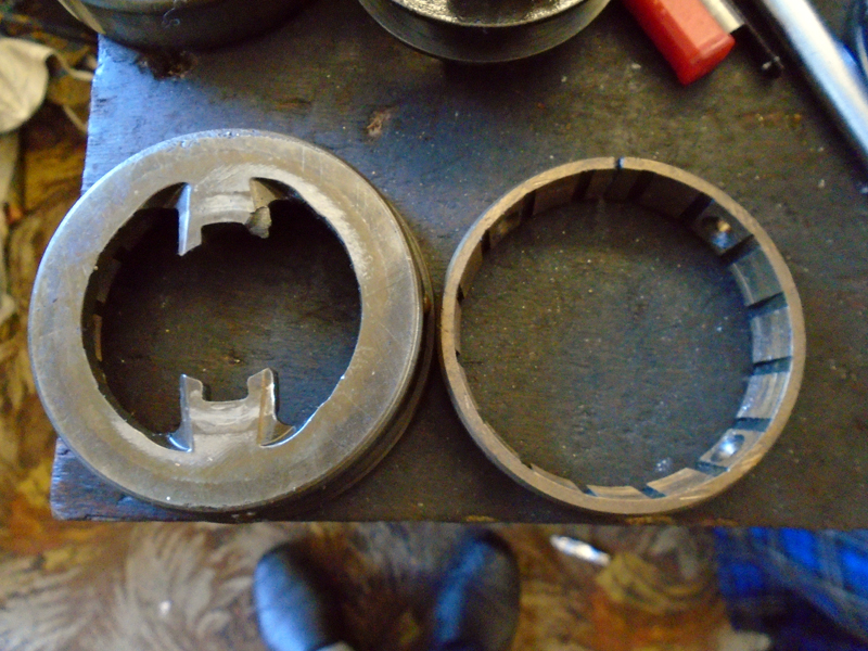 2: This shows associated damage to the synchro plates, all caused by aggressive gear lever "thrusting". Sent from Belgium, November 2020. 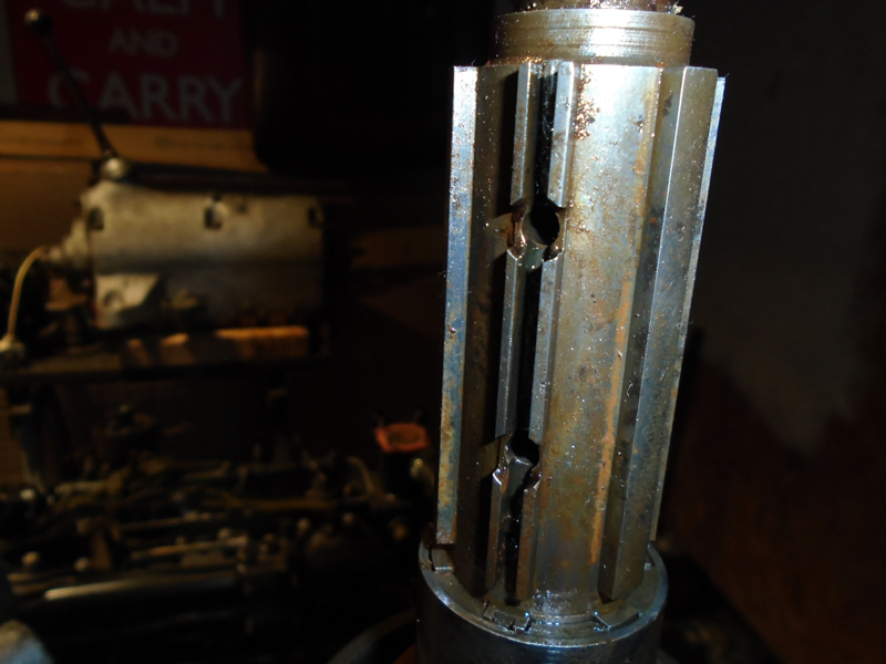 3: This shows the early split main shaft, RG 193, the thinned splines of which break off by synchro lug action, often due to the original use of engine oil, causing the bronze synchro liners to stick on. (Message approved by david_gore) | ||
Jeff Martin Experienced User Username: jeff_r_1 Post Number: 185 Registered: 07-2018 |
WOW ! What a mess, mine is quite pristine compared to that ! Those are great pictures. Thank you. I think I have the squared shouldered bearings in mine too. I can see that just looking at the areas where the snap ring gap is. I know that someone has been in my gear box at some point, one of the three bolts that holds the shift slider in place has been changed to 1/4 x 28 UNF from BSF. It's the one right next to the floor, it would be almost impossible to get at with out removing the gear box, or the floor. | ||
ChristopherCarnley Unregistered guest Posted From: 159.242.227.80 |
Use EP 80/90 gear oil and a dose of Slick 50 Manual Transmission treatment. What is the condition of the bronze synchro liners, have they got the fine annular grooves? I have used diamond plates to polish the hub cones, but it makes little difference. (Message approved by david_gore) | ||
Jeff Martin Experienced User Username: jeff_r_1 Post Number: 186 Registered: 07-2018 |
After carefully examining the bronze synchro liner on the the 4th gear, that seems to be the problem, even though the photo looks normal for number 4, they are almost worn away. When it's compared to second gear, it's quite worn. Unfortunately the only source for a new one that I've found so far is at Flying Spares that rings in at around 2700.00$ Canadian.   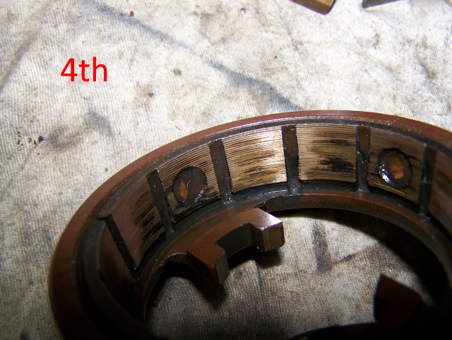 | ||
ChristopherCarnley Unregistered guest Posted From: 5.62.43.178 |
Hi Jeff, It has been burnt by too close a contact with the 1st motion hub. People will persist with the old 30 grade engine oil. When you read section G of the W.M. you will see that there should be an equal gap of around .025" between the end of the bridge key and each of the 3/4 synchro plates. Flying Spares get all their bits from me, so when you see the pics that David may post I will post my email for contact. If you have a lathe you may be able to cut some fine grooves, the originals have a spacing of less than .008", and the taper on the lining is 7 degrees. The sliding piece is not symmetrical, and some of them have "FRONT END" engrave on them. If you have drawn the 4th speed selector shaft too far forward, you may have dislodged the 3rd/4th 5/16" interlock ball, see diagram, and if you then remove the little selector shaft cover from the lower back, it may drop out. The interlock is not the same as the 1/2" detent balls. C. I have received some additional photos from Christopher which he intends commenting on after I post them. Unfortunately, I am unable to process and post them until this evening as I have to leave now to drive to Gloucester for a family funeral. (Message approved by david_gore) | ||
David Gore Moderator Username: david_gore Post Number: 3877 Registered: 04-2003 |
Here are Christopher's photos relating to my last comment - my apologies for the delay: 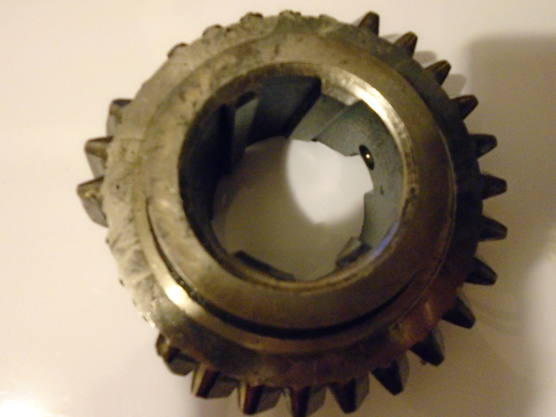 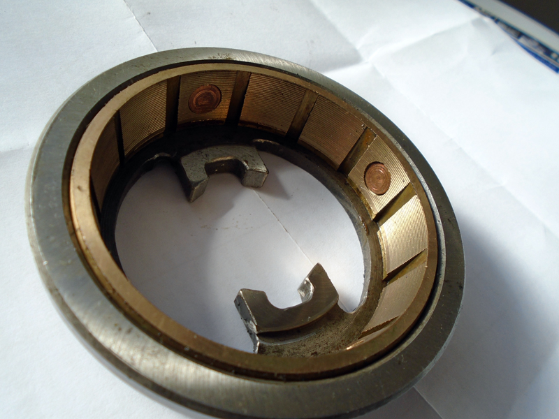 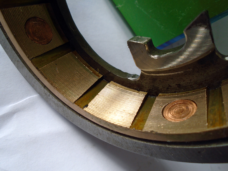  | ||
Jeff Martin Experienced User Username: jeff_r_1 Post Number: 187 Registered: 07-2018 |
Thank you Chris, I have some reading to do. This is my first transmission repair so bear with me, as I'm dealing with unfamiliar terminology. What is the "bridge key" and "3/4 synchro plates" ? You also refer to a diagram when talking about "dislodged the 3rd/4th 5/16" interlock ball", what diagram exactly ? Yes, I do have a lathe, just got it, a Myford ML7, but I may get a machinist to do it, I can make simple things with it like bushings and such, but I don't feel comfortable with such things as this. If I re-machine the burnt synchro, will that remove too much material and move it too close to the gear over-all ? | ||
ChristopherCarnley Unregistered guest Posted From: 5.62.43.188 |
Hi Jeff, Download Section.G from the Workshop Manual, and also S.G from the Parts List, both on the MKVI/R Type entry on the Post War Library ,on this site, and I will come back to you. C. (Message approved by david_gore) | ||
Jeff Martin Experienced User Username: jeff_r_1 Post Number: 188 Registered: 07-2018 |
I do have real paper copy of both of those, although they differ slightly here and there. I found a machinist that can recut the grooves, so I would just like to confirm things, see photo's. Each groove is then how deep at 8 thou apart ? And the taper is 7 degrees like I marked out ? Thanks again. 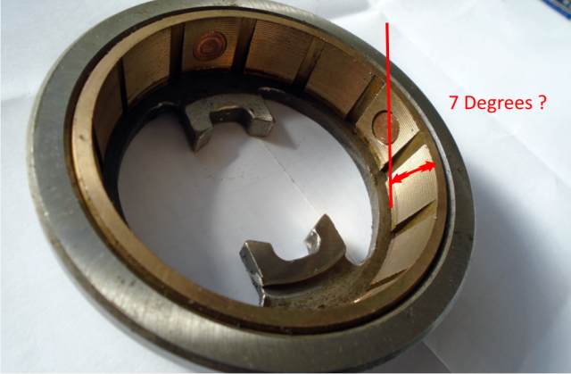 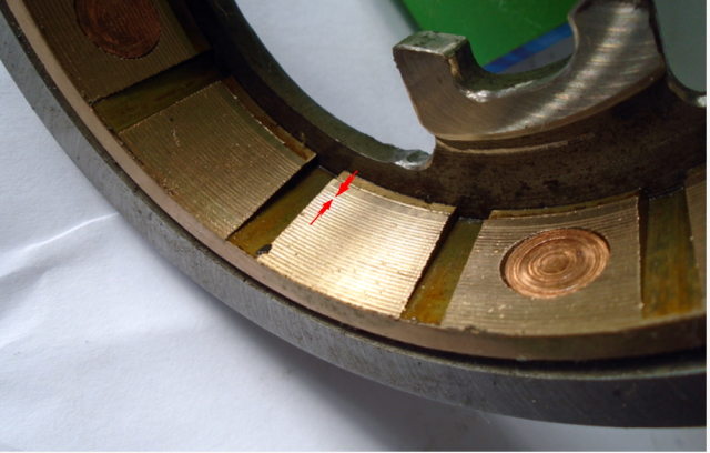 | ||
AlexLynch Unregistered guest Posted From: 220.244.177.227 |
Hi Christopher Carnley, I am also rebuilding my MK V1 gearbox, B111 JN. From previous posts, I see that you have the square faced bearings for the first and third motion shafts. I have a J series vehicle with the the reinforced shaft. Can you provide me with your Email address so I could contact you directly. Regards Lex Lynch Registered Guest (Message approved by david_gore) | ||
Jeff Martin Experienced User Username: jeff_r_1 Post Number: 189 Registered: 07-2018 |
Chris, I've been reading through G section and so far I can't find anything in there that refers to a "3/4 synchro plate", synchro cone, but not plate. Yes, the sliding piece is not symmetrical, mine is not marked front, but it can only go in one way anyway. It can be turned around in the correct position, but turned end for end. The dog teeth have to be fitted in their third and fourth gears respectively because they have smaller and larger diameters. I'm still working on what "diagram" you are referring to. | ||
Jeff Martin Experienced User Username: jeff_r_1 Post Number: 190 Registered: 07-2018 |
Here's a photo from Introcar, what can happen when the "square edged" bearing isn't used on the first motion shaft. Take note that the bearing only has one square edge, and that goes up towards the snap ring. I also took some time to try and find another source and came up with nothing, the bearing appears to be specially made so one has no alternative to pay the �430.55. 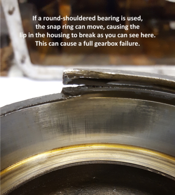 | ||
ChristopherCarnley Unregistered guest Posted From: 159.242.227.100 |
Hi Jeff, I was tied up all day yesterday with an S3 13/38 differential and half shafts. Everything is so tight, the drive flange nut came off with the mains ratchet, and the drive flange came off in the 30 ton press with the usual "bang". For the driver not to be able to "catch the synchro", the R-R designers used a blocking plate type synchromesh cone, almost unique, the ramp action of the sliding piece on the cone ramps, ensures that the bronze liner is jammed on before the dog teeth make engagement. The bridge keys (15) on the diagram, nudge the cone, as a brake, to synchronise the input with the speed of the main shaft. I have asked David to post the pictures. The cone angle is 7 degrees as you mark, and the tool to machine the grooves can be a HSS internal thread cutting ground thin to about 20 degrees. There is no evidence that your cone has bottomed on the gear hub, but it is a mistake to fair face the liner. The material is heat treated phosphor bronze and very tough, so cutting should be with the lathe at high speed and next to no top rake on the tool. In practice, you only need about half the grooves if you are using gear oil. I have never experienced any problems with round shouldered input bearings in normal use, but as the thin lip is the only part holding the input shaft and bearing in position, I have had them knocking the whole lip off when the input shaft spigot end has been rammed against something or dropped on the floor when loose in a packing case. A square edged bearing won't prevent this, and the spring clip never moves, as its ends anchor it. It is false information. The back bearing causes the problems, it is loose in the housing as the bore in the aluminium housing enlarges when it gets hot in use as it is not an interference fit. Alex, If your square edge bearings are not corroded with obvious pits, it is a waste of money to replace them "for the job". In normal use and well lubricated, they should last indefinitely. At about �560 for the pair in a batch of 20, I never replace them, if they are in good nick. Chris. carnley3rt@btinternet.com (Message approved by david_gore) | ||
David Gore Moderator Username: david_gore Post Number: 3880 Registered: 04-2003 |
Jeff, Christopher's email address in the above post has a typo error, the correct address is: carnley3rt@btinternet.com Christopher has forwarded the following parts diagrams for me to post on his behalf as mentioned in the above thread: 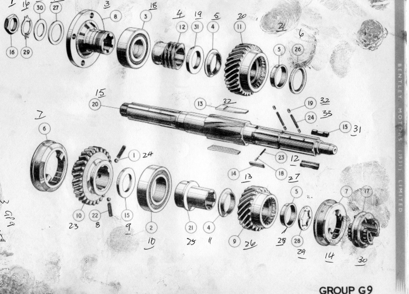 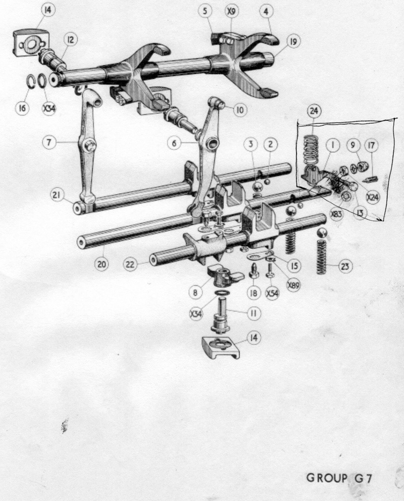 | ||
Jeff Martin Experienced User Username: jeff_r_1 Post Number: 191 Registered: 07-2018 |
Thanks Chris, it's all coming together in my head now. You mentioned the word "thread" when referring to the bronze synchro cone, is it a thread (spiral) or just individual grooves cut one at a time ? If it is a thread, that could throw a wrench in things. Lex, I would like to see what is wrong with your transmission, if you could post some photo's of the failed bits, posting actual photo's on a thread like this becomes invaluable to others who would like to work on their own stuff, but never had the courage to do so. | ||
ChristopherCarnley Unregistered guest Posted From: 5.62.43.139 |
Jeff, No, not a spiral, but a "thread cutting tool", ie for cutting threads, but ground thin. They are individual grooves. The interlock ball mentioned previously is No 2, in Group G7. The parts in the Biro,ed box are in the 1st speed detent roller, fitted to cars from the N series, on. Curiously, the 1936 on Lagonda G10, (big horrible Bentley/Sewell monster) has duralumin synchro liners, with a continuous screw thread for the oil tension release groove. All the MK VI/R Type and S1 main shafts are the same part, be it RG193 or RG5469 etc, but the early one had the spline milled out for the thin sliding key, the others had altered thrust washer grooves, and thicker washers. Alex, so would I. C. (Message approved by david_gore) | ||
Bill Vatter Experienced User Username: bill_vatter Post Number: 133 Registered: 09-2004 |
Chris, Regarding the square-edge bearing issue, I understand the problem is that the contact of a standard, rounded-edge bearing against the retaining ring would be at a location on the retaining ring a small distance away from the bore of the housing. Then when pressure occurs, the force on the retaining ring creates a lever effect, breaking the housing bore. The square edge bearing avoids that by placing the contact at the bore, and there is no lever effect. Axial force described above is a natural result of the helical gear connection of first and second motion shafts and cannot be avoided. Did I get that right? | ||
ChristopherCarnley Unregistered guest Posted From: 5.62.43.251 |
Bill, You did. (Message approved by david_gore) | ||
AlexanderLynch Unregistered guest Posted From: 220.244.177.227 |
Hi David, I registered 07/20 user name" lex lynch" with a keychain password but i am unable to to access my account, please advise regards Alex Lynch. (Message approved by david_gore) | ||
David Gore Moderator Username: david_gore Post Number: 3882 Registered: 04-2003 |
Alexander, Unfortunately I do not have access to the Users File to see what is the current status of this registration. Please contact the Forum Administrator using the link below: admin@rrforums.net Your previous registration as Alex Lynch was last active in 2002 as far as I can find from searching our archives. Have you tried using the forum "Lost Password" to try and recover your access for this User Name? 1. Open the Forum and click on "EDIT PROFILE" in the top right-hand corner. 2. A page headed Profile Editor will open with a box headed Log In with data entry boxes for Username [Alex Lynch] and Password [leave blank]. 3. There is a link "click here to restore access" with format http://au.rrforums.net/cgi-bin/forum/board-profile.pl?action=forgot 4. This opens a new page headed "Recover Forgotten Password" with boxes for Username and Email Address. I would only enter one of these being your email address and hit the "Continue" button. If this does not work, repeat the process with Alex Lynch as the username and no email address. 5. If both of these don't work, try entering both your Username and Email Address and see what happens. 6. If successful, this should result in an email with an activation key for your account. Reopen the Profile Editor page and enter the activation key using the link provided on the bottom of the page and all should return to normal. 7. If this fails, you will have to rely on our Administrator to reactivate your account - as the Moderator, I do not have this capability.......... 8. Good luck and I hope this succeeds - if not, I am happy to continue posting on your behalf as above. P.S. Your IP address has changed from the one used for your 2002 posts. | ||
Alexander Lynch New User Username: lex_lynch Post Number: 4 Registered: 07-2020 |
Thank you David, I think I have that sorted Regards Lex | ||
David Gore Moderator Username: david_gore Post Number: 3883 Registered: 04-2003 |
Alexander, Yes you have succeeded - looking forward to your future contributions. Welcome back...... David | ||
Alexander Lynch New User Username: lex_lynch Post Number: 5 Registered: 07-2020 |
Report on rebuild of gearbox for 1950 Bentley B111 JN - Alex Lynch. Thank you to Christopher C for clarifying the continued use of the square edge bearings. The reason for this rebuild was that on the final leg of a trip to Western Australia, we arrived in Margaret River where I selected reverse without using the clutch. I live in Melbourne 3,500 K away, so I was somewhat traumatised by the prospect of returning home with a damaged gearbox, the trip however proved uneventful. 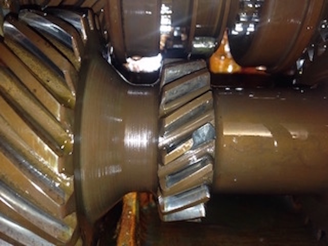 Pic 1 second motion shaft with chipped tooth. I copied the Service Manuals from this site and also had on hand the Spare Parts Manual with the exploded drawings. Also purchased was an early gearbox salvaged from a bushfire damaged vehicle. This was dismantled first to give me the experience interpreting both the manual and the physical components. I have kept my original gearbox and transferred the first and second motion shafts as they are paired and kept my upgraded third motion shaft with the modified bridge, plungers and sliding piece. 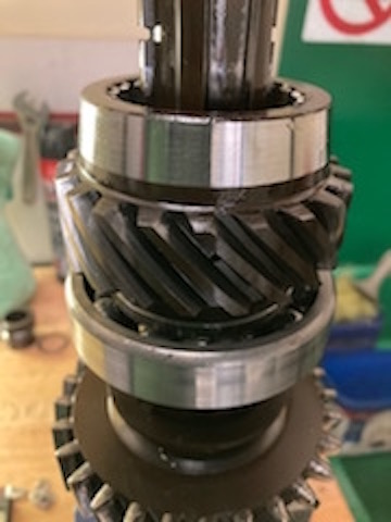 Pic 2 Gears and cones were transferred from the early third motion shaft together with reverse gear. There were two occasions where initially I had trouble understanding the manual, �Dismantling the Gearbox� (xix) �removing the 5/16 balls from the third and fourth speed selector shafts and the removal of the first speed gear. 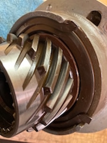 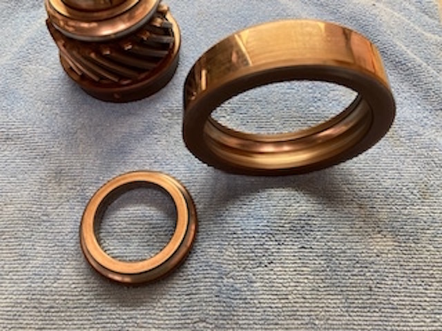 Pic 3 & 4 I have ordered new tapered, centre and servo bearings but retained both square edged first and third motion shaft bearings as they show no signs of wear. 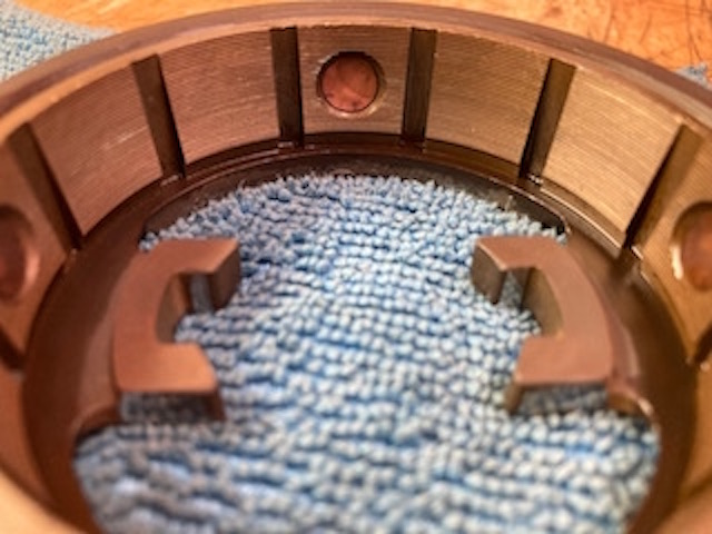 Pic 5 first motion shaft cone This is where I have progressed to to date, with the arrival of the bearings the final set up and reassembly can proceed. . | ||
Alexander Lynch New User Username: lex_lynch Post Number: 6 Registered: 07-2020 |
When I dismantled the third motion shaft from the Gear Box in B111 JN this spacer was between the worm of the servo unit and the first race of the rear bearing. In the doner gear box there was no such spacer in this position so I feel that the last person placed it there possibly to get a nip on the nut of the rear flange which is unnecessary as there is .090 between the adjusting washer and the machined flange which is within specs. 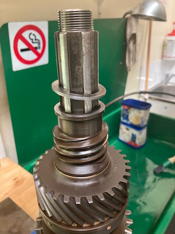 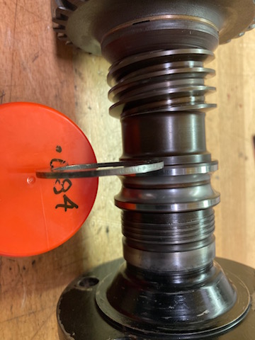 | ||
Jeff Martin Experienced User Username: jeff_r_1 Post Number: 192 Registered: 07-2018 |
Placing it there looks like it's going to move the entire third motion shaft back into the transmission the thickness of the spacer. This would effect the position of the centre bearing, fork position and many other things. Maybe the casting was different in your car and it needs to be there. The third motion shaft "square edge bearing" inner race places the position of the shaft's out-put flange and has no effect on the threads in that respect. That's assuming the spacer goes where you said it is. If you moved the spacer where the red arrow is, then doing that would simply move the out-put flange toward the back of the car and would reduce the amount of threads on the third motion shaft. Where you have it now will move the entire third motion shaft toward the front of the car. 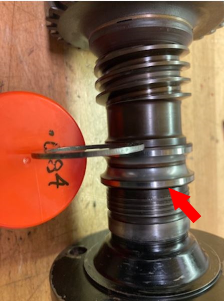 | ||
ChristopherCarnley Unregistered guest Posted From: 5.62.43.244 |
See parts list drawing G9 above. No 27 is the adjusting washer to fill the gap in the drive flange and prevent preload on the bearing, No 30 is the nut washer. One fool, upon reading an amateur article where the "mechanic" had ground metal of the inner race, declared that the bearing is under preload. The bearing has a C3 fit, quite loose as it get hot in service, and closing up the races makes the balls skid. The washer in your pic should just fit into the recess in the drive flange. (Message approved by david_gore) | ||
Alexander Lynch New User Username: lex_lynch Post Number: 7 Registered: 07-2020 |
Yes, I rather think I got my sequence of parts out of order. thank you all for your feed back. I will post another report with photographs as I get to the assembly stage of the box. | ||
David Gore Moderator Username: david_gore Post Number: 3886 Registered: 04-2003 |
Christopher Carnley has provided more information as below, my apologies for the delay as I have been having problems with my mobile broadband and phone connection since returning to Sydney last Thursday. 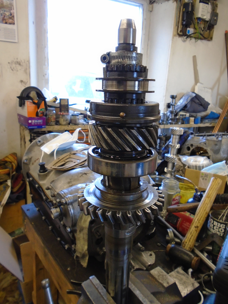 Notes for pic 1. Build up to this stage fit the Jubilee clips on tightly, check that the sliding piece will engage into the 3rd speed driven gear dogs. This gear should revolve quite freely on its bushes or selection will be difficult. If you add the second speed parts, it is very difficult to juggle the forks on. Grease lightly the outside of the bearing. Place the selector forks into the bottom of the casing, noting that one fits "upside down" to the other. 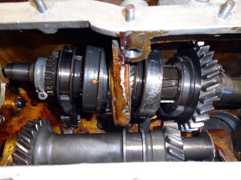 Pic 2. Push the reverse cluster forward. Insert the main shaft as shown. Cock up the end of the back end of the shaft and fit the 1/2 fork. Drop the back end and fit the 3/4 fork. Heat the central alloy bearing bridge with a blow torch for about 30-40 seconds, juggle the bearing into the orifice whilst easing the forks with left and right hands. This avoids hammering and dislodging the plungers. You may have to push the reverse cluster back. Drop the forks onto the pegs and then fit the locating shaft from the front. The 1/2 fork is a bit tricky. Remove the front clip and fit the 4th speed cone the right way round and onto the central spline. Fit the 14 rollers into the 1st motion gear and its assembly cup. Fit the assembly and the 6 nuts and spring washers. Fit the 2nd speed synchro, its chamfered adjusting washer the gear with bushes and then the thick chamfered adjusting washer, then a clip as shown in pic 3. There should be about a .002" -,003" gap between the washer and the flanged bronze bush. 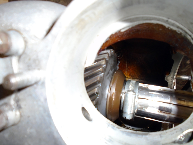 Notice that the years of EP oils have not caused any "yellow metal hysteria" deterioration. . | ||
Jeff Martin Experienced User Username: jeff_r_1 Post Number: 193 Registered: 07-2018 |
That orange/yellowish coating on the inside of the aluminum casing looks like orange shellac, is that what it is ? There's run marks of the stuff that makes me think that someone in a hurry with a big sloppy brush applied it. The colour of it looks just like shellac, I put a bit of paint stripper on it, but it didn't really touch it. | ||
ChristopherCarnley Unregistered guest Posted From: 80.75.64.70 |
Jeff, It is factory applied long oil varnish, with a hardener. It is to counteract any porosity. The later R Type and Continental gearboxes do not have this internal finish. The only occasions when it has been seen to degrade are when the car has been fire damaged or serious internal oxidation of the alloy has occurred. C. (Message approved by david_gore) | ||
marktaxis Unregistered guest Posted From: 144.134.5.170 |
Before I started reading this post I was aware that my knowledge of gearbox operation was limited, now I realise it is pretty much non-existent! As a matter of interest What would be a ball park figure for a complete rebuild of one of these gearboxes (Message approved by david_gore) | ||
Jeff Martin Experienced User Username: jeff_r_1 Post Number: 194 Registered: 07-2018 |
Mark, what are the symptoms of your transmission where you think it needs rebuilding ? | ||
Jeff Martin Experienced User Username: jeff_r_1 Post Number: 195 Registered: 07-2018 |
Chris, I'm getting ready to cut the grooves on the 4th synchro cone and I've taken some practice runs on a piece of brass, even at 10 thou, the grooves seem much finer then the close up of the 2nd gear synchro cone, or maybe they are that fine on 4th gear ? Also, there seems to be a lot of meat left on the top end of the grooves on 2nd gear, yet in your photos it appears to be a sharp point, or maybe it's just "wear" on the 2nd gear synchro cone ? Should I be leaving some meat on the top of the grooves ? 8 thou just seems really fine and only 2 thou deep, the original grooves just didn't seem that fine. I think I also have to grind my bit closer to 20 degrees. I don't want to bugger it up, I don't think the local auto store has a new synchro in stock.  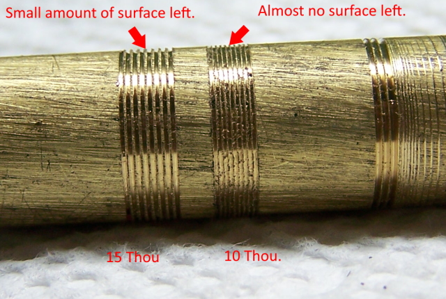 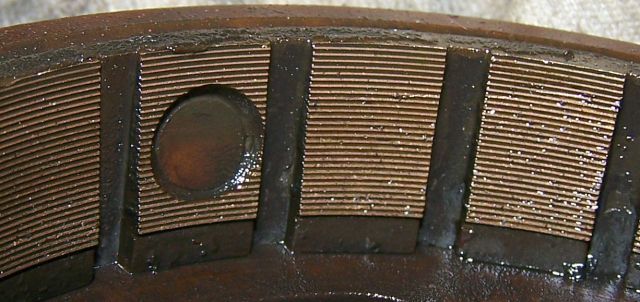 | ||
David Gore Moderator Username: david_gore Post Number: 3889 Registered: 04-2003 |
Jeff, Chris Carnley has asked me to post the following drawings with the comment below: "I should have checked what I wrote"! 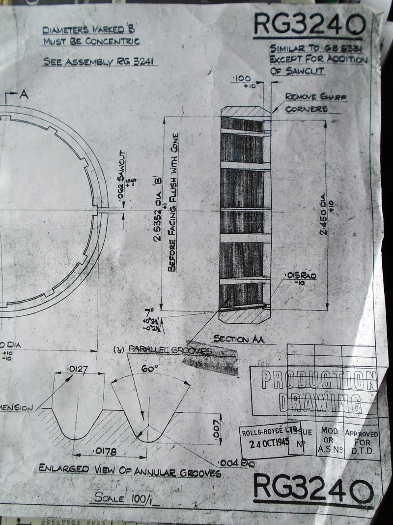 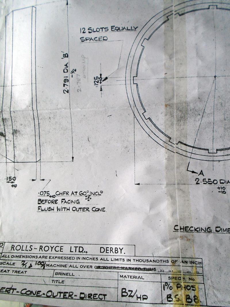  . | ||
David Gore Moderator Username: david_gore Post Number: 3890 Registered: 04-2003 |
Wait there is more from Chris: "Final "scrap", the "direct gear" is 4th speed." 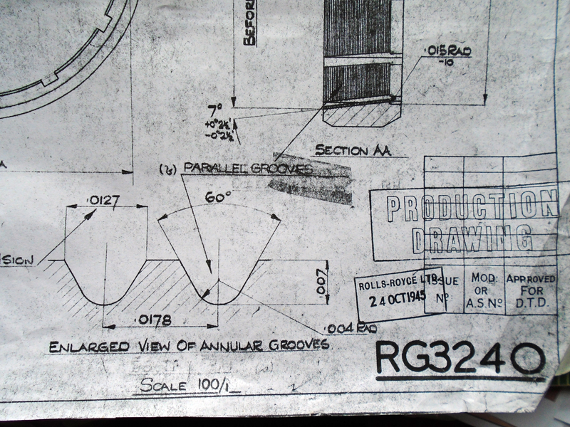 | ||
Jeff Martin Experienced User Username: jeff_r_1 Post Number: 196 Registered: 07-2018 |
Perfect, I'm glad I asked ! | ||
David Gore Moderator Username: david_gore Post Number: 3892 Registered: 04-2003 |
Christopher and Jeff, Thanks to both of you for your contributions to this thread which I am certain will be most useful for other owners and custodians of early post-WW2 vehicles. I have enjoyed facilitating and posting your invaluable contributions. Now I am awaiting Jeff posting pictures and the details of his car returning to "active service". | ||
Jeff Martin Experienced User Username: jeff_r_1 Post Number: 197 Registered: 07-2018 |
Thank you David, Chris and others, this is my first transmission, and with out the very useful photos and info, it would have been quite difficult to get through it. I'm still waiting on the modified thrust washer from IntroCar, I'm contemplating just using the old one. It's been in there for more then 20 years and it's done fine so far. Just setting up the lathe to cut the grooves in the synchro cone. I plan on assembling it in a different way which will also make it far easier getting it back into the car, I will post that when the time comes with photos. Things will move along kind of slow, dialysis eats up about 6 hours 3 days a week, I run, cycle and work out with weights and look after the house and sleep a lot. I still need to work on the suspension before winter sets in, 2021. The nice thing about this is it's not a car that has to be on the road as a daily driver, it's in a heated garage and I can work on it anytime I want and enjoy myself. This is me in front of my time trial bike for anyone who wants to what I look like.  | ||
Jeff Martin Frequent User Username: jeff_r_1 Post Number: 209 Registered: 07-2018 |
Shows the 4th gear synchro cone after re-cutting the annular grooves on the lathe. If you look closely there is a slight discrepancy in the pattern of the grooves, I ran out of travel in the compound feed and had to reset it. I bought this magnifying helmet with this bright LED light on it, like the kind a dentist would use, and I simply could not see clear enough to start the next cut _ I don't think it's going to be a problem. Book says .0178, my lathe does not do 10,000s of an inch so a rounded it up to .018 thou. Just doing a trial run on a different way mounting the third motion shaft, seems to make more sense. The end bearing and cover determines where the centre bearing mounts, and after using a heat gun for about 5 minutes on the casing, the entire third motion shaft just dropped in, cover and all. The same heat gun method worked very well to get the square edged bearing in its housing at that end, about 5 minutes of heat, slowly moving it around and the bearing just dropped in with no effort at at all. 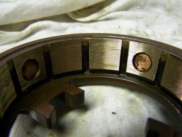 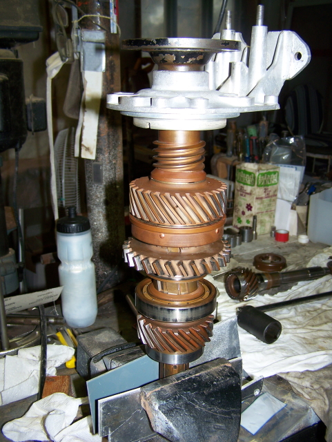 | ||
ChristopherCarnley Unregistered guest Posted From: 159.242.227.60 |
Excellent, so far. Have you entered the 3rd motion into the casing? (Message approved by david_gore) | ||
Jeff Martin Frequent User Username: jeff_r_1 Post Number: 212 Registered: 07-2018 |
Not yet, waiting for gaskets and seals from Introcar. But I did do a trial run and just slips in. I've also realized that the reverse motion shaft has to be in place first if the cover for the third motion shaft is in place. The shaft for the reverse gear can't be slipped into place with the cover in the way. I don't see a problem using the original thrust washer, after all it's been in there for the 20 years that I have had the car and who know how long before that. I don't see the need for the thicker one given the fact that both square edged beading are in there. I was going to wait for the "thicker" thrust washer from Introcar, but it's out of stock and has been for months. It was supposed to show up at the end of March, but hasn't, so who knows when, could be weeks or months. Also, I have to see if I can get the forks and related hardware back in place with the reverse gear and shaft in the way. | ||
ChristopherCarnley Unregistered guest Posted From: 5.62.43.164 |
Jeff, The thicker washer .275" thick will require the later parts mods. ie .050" ground out of the 3rd speed gear. ditto the bearing sleeve, .021" from the sliding piece and the washer groove has to be widened. You can only insert the 3rd motion shaft as I have shown above on 21st Feb. Chris. (Message approved by david_gore) | ||
Jeff Martin Frequent User Username: jeff_r_1 Post Number: 214 Registered: 07-2018 |
Yes, about the third motion shaft. I was doing some experimenting tonight and there is no way to get the forks in place with the reverse motion shaft in the way. Even placing them in position, there is no room to get them in position. Too bad the designers didn't make a hole in the cover to slip the reverse shaft in place with the cover in place. The hole could have simply had some sort of cover or plug to take car of the hole. I took the reverse motion shaft out to free up the forks, so that's the way I'm going to install them. | ||
ChristopherCarnley Unregistered guest Posted From: 159.242.227.53 |
Jeff, How will you replace the reverse cluster gear shaft and its bronze faced thrust washer? How will you fit the 3rd speed synchro cone, springs, 4 off plungers, 2 off bridge keys, and the sliding piece, that the 3/4 fork slips into? How will you fit the servo drive cross shaft? (Message approved by david_gore) | ||
Jeff Martin Frequent User Username: jeff_r_1 Post Number: 216 Registered: 07-2018 |
I'll have definite answer soon, but I can answer some right now, maybe I'll even make a video. The reverse cluster can easily be fitted after the third motion shaft is in place, but the rear cover has to be off _ as I learned. The 3rd speed synchro cone, springs, 4 off plungers, 2 off bridge keys, and the sliding piece, that the 3/4 fork slips into, will already be in place like in your photo, but with out the fork(s) in place. The servo drive cross shaft can be installed after all three drive shafts are in place, the servo shaft is one of the first things that came out when I took it apart. The keeper of the small bearing on the servo shaft is removed and the whole thing simply is drawn out from its big end bearing _ I used a very large socket and threaded shaft for this. The servo drive has to be removed first in order for the third motion shaft to be withdrawn. With out the reverse cluster in place, the forks should just slip into place and the shaft that the forks slide on is slid into place while I hold the forks in position. (so the plan is) There is plenty of room to get the forks into place with out the reverse cluster in the way. I'm pretty sure that's how I took it apart, but it's been a little while so I can't be too sure, I'll find out tomorrow. Thanks for your questions, I'll have some more too about the 3rd and 4th speed interlocking ball, I don't remember it ever dropping out, I'm pretty sure it was missing. I have a new ball, but I can't figure how it is installed between the two shafts where it actually does anything, it's too small to lock anything and catch in the grooves provided in the 3rd and 4th shafts. | ||
Alexander Lynch New User Username: lex_lynch Post Number: 8 Registered: 07-2020 |
I have just completing the assembly of the First, Second and Third motion shafts plus the servo and speedo drives. Christopher I followed your suggestion with the Third Motion shaft leaving off the second gear and servo components. After a bit of juggling the forks dropped into placed together with the centre bearing into its housing. The guide shaft for the forks slid into place and the second and worm gear components attached. The First Motion Shaft was bolted up then the square edged rear bearing. All other bearings were replaced. New parts were an adjusting washer (9) beside the centre bearing, all new bushes for the gears, reverse bronze washer and gaskets. The clearance for the thrust washer is .002. The second motion shaft has a pre load of .004 and the coupling flange stands out beyond the shaft by .010. The 2nd speed cone was adjusted thru the eccentric pin to give a clearance of .025 although I noticed this could vary after the shaft was revolved a few times. the 3rd and 4th speed cones have a clearance between the bridge and the rear face of .035. All selector forks, shafts and ball bearings were removed and checked, greased and replaced. Although there is an initial slight resistance the gears revolve freely when you hold the first motion shaft and turn the coupling flange. I have enjoyed discovering the intricacies of this gear box. It is a delight to work on and a beautiful piece of engineering. The service instructions do eventually make sense, together with the help of Christopher Carnley, your input is greatly appreciated. Lex Lynch 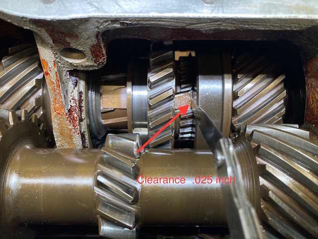 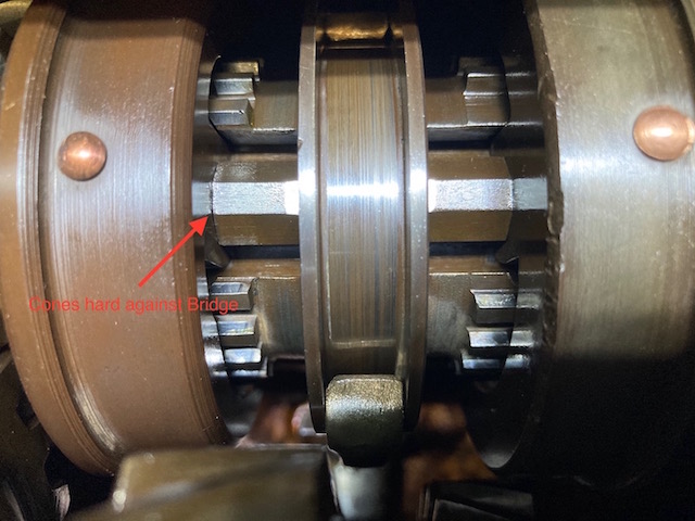 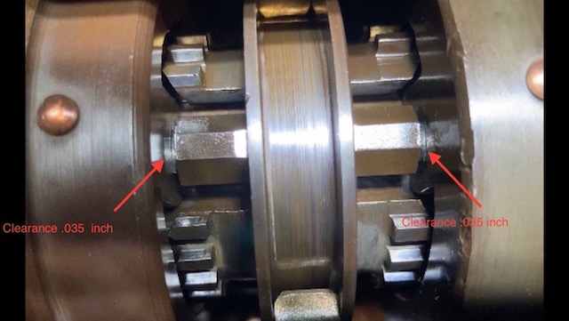 | ||
Jeff Martin Frequent User Username: jeff_r_1 Post Number: 217 Registered: 07-2018 |
I may not know what I'm talking about, but shouldn't the centre bearing be equally in the housing, it looks like the shoulder of it is poking out a bit ? Mine is centred in the housing when its all back together. Or maybe it doesn't matter. See BLUE arrow. 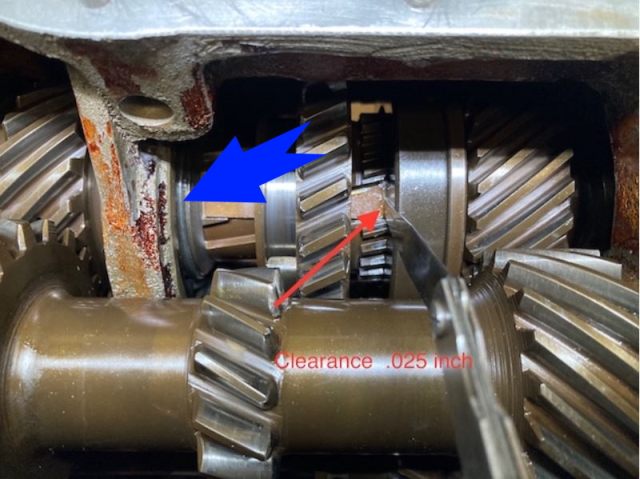 | ||
Jeff Martin Frequent User Username: jeff_r_1 Post Number: 218 Registered: 07-2018 |
Here you go Chris. It just seems simpler not having to jiggle the whole third motion shaft around and trying to engage the forks at the same time. The trick is that the centre support bearing has to be sticking out around 1/2 way so the fork can clear the off set shaft key on the other side of the casing. Once the forks are in place the centre bearing can be moved into the correct position when the cover is installed. I'm no Stephen Spielberg, but it shows it well enough. https://www.youtube.com/watch?v=lvX8JvA-YGc https://www.youtube.com/watch?v=_ynDQq85ZJk | ||
ChristopherCarnley Unregistered guest Posted From: 5.62.43.135 |
Alex, That looks "text book", great job. Did you check that the sliding piece is the right way round? Oil is EP 80/90 or 90. Chris. (Message approved by david_gore) | ||
ChristopherCarnley Unregistered guest Posted From: 5.62.43.135 |
Jeff, I think that you are looking at the bearing inner race, a bit parallax. You should follow Alex and strip it right down as the book, or you will never get the thing back together. I have asked David to post pictures to help you through the interlock ball dilemma. Pic 1 shows the side of the case and the black circle indicates the drilling for the 5/16" interlock balls, plugged with peened over aluminium rod. Note the notch in the rear gasket which is necessary to prevent hydrualicing of the shafts. Pic 2 shows that the detent springs and 1/2" balls have been removed. A spray of degreaser should release them. Pic 3 shows the groove in the side of the 3/4 shaft that the interlock ball slips into. You may recall that I mentioned that if you draw the shaft too far forward that this ball may fall out. Pic 4. when the shaft has come this far, the ball is loose and may drop out into the shaft bore BUT IT MAY DROP INTO THE DRILLING OPPOSITE. The gearbox of Alex has had little use, and there is only minor tip fretting of the 1st driving gear teeth. Replace the 3/4 lever onto its peg, and with a blob of yellow grease holding the ball on the end of a screwdriver, insert it into the back of the bore and then into the little recess next to the 1/2 shaft. There is only the WM version of the reassembly that works, but I have simplified as I can have as many as 7 on the bench in all sorts of condition and "make it easy on yourself". Chris. (Message approved by david_gore) | ||
David Gore Moderator Username: david_gore Post Number: 3900 Registered: 04-2003 |
I have received the pictures from Chris and will post them this evening as I have other commitments today that will take all of my available time. | ||
Jeff Martin Frequent User Username: jeff_r_1 Post Number: 219 Registered: 07-2018 |
Thanks Chris, I had it back together, I guess the video didn't convey that. Yeah, the video is pretty crappy. I did figure where the ball goes later on and that mechanism works well now. Yes, I see now about the bearings inner race and what you mean by parallax... Sorry, the book is just too confusing, it's not written for people with no experience in the disassembly or reassembly of a given transmission. It's good for looking up specs. though. If I were to read through it, now that I'm familiar with the unit, it would probably make perfect sense. You don't know anything about me, but give me some credit, I'm not a total green horn when working with mechanical things and this is just one more mechanical thing. Sorry, the work shop manual is not the end all, beat all method that works for reassembly. I took it apart in a sequence that I'm familiar with and it's going back together in the reverse of that sequence, whether or not it agrees with the manual is of little consequence at this point. Don't get me wrong, I do very much appreciate your help in answering my questions, especially when it came to the synchro cones, the annular grooves and their specs. | ||
Alexander Lynch New User Username: lex_lynch Post Number: 9 Registered: 07-2020 |
I have a query about the coupling flange nut and adjusting washer. When the nut is loose I am able to spin the 2nd and 3rd gears on their bushes ( in neutral ) but on tightening up the nut it locks both, I understand this is an adjusting washer issue in the coupling flange but to what degree with a fully tightend nut are the gears meant to be able to turn. My original adjusting washer does have a depression mark where the top washer has bed into it. At present there is a 0.10 + where the flange stands above the shaft. Attached pic is of the forward side of the central bearing housing 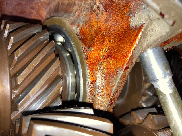 | ||
Alexander Lynch New User Username: lex_lynch Post Number: 10 Registered: 07-2020 |
Chris I forgot to say that I double checked and the the selectors are entered correctly and I definitely will fill the box with EP 80/90. With thanks Lex | ||
ChristopherCarnley Unregistered guest Posted From: 159.242.227.127 |
Alex, It looks like you may have adjusting washer problems. Take the drive flange and the rear housing off, then drive the central bearing backwards until the outer race is level wit the central bridge. You could heat the alloy a bit before getting the drift onto it. The thick (.365") washer behind the 2nd speed gear bush determines the 3/4 synchro key position and spacing, and when all is tight there should be a small gap .002" between the washer and the flange. If this washer is too thick and they go up to .405", it will jam the gear box. When I have to modify an early box and fit a later shaft, I have to quite often, fit a .335" washer and grind a bit off the servo drive scroll to get bridge key clearance. When the washers are "right" the end nut can be fully "tight" but never flogged, and the gears will spin and you can hold the input shaft and turn the output flange. Give the W M rebuilding notes regarding washers and clearances, a bit of attention. Jeff, If there is no damage or rust, I never remove the reverse shaft, but your method of replacing the forks would seem logical, if I did. Did you manage to replace the interlock ball. About 4 years ago I had the gearbox and rear axle of a pre war Wraith to overhaul and repair. The rear axle was straightforward but the gearbox is a nightmare when compared with the MK VI. I got fed up reading the "secret" instruction sheets compiled by both Vic Allen and Stanley Bull at Hythe Road in 1952 1nd 1958, and dived in. When the numerous tiny needle rollers fell out, I should have stopped. Anyway, Andrew Wood and I had a laugh about it a bit later on when I sent him a copy. The MK VI gearbox is a rational version of the 1939 MK V one, and we were discussing this as he and Paul had a a MK V saloon but when they came to the overdrive gearbox, found that the Rolls-Royce Service Station had replaced the rather fragile and unavailable MKV innards, with a standard MK VI gear train. This box came to me later on for overhaul. (Message approved by david_gore) | ||
Jeff Martin Frequent User Username: jeff_r_1 Post Number: 221 Registered: 07-2018 |
Thanks Chris, yes, I did manage to replace the interlocking ball. Not sure what I missed the first time around, but it works now. I just removed the reverse shaft as it was easy to get out and made more room to remove the forks, and finally, the third motion shaft. Also, it was just so dirty in there with this oily sludgy dirt all over everything. It pretty much had to all come apart for a thorough cleaning. The only thing I left in there were the selector shafts. I used a water based engine degreaser and went at it, I then brought the case into the bath tub and used hot water to thoroughly rinse it off. I then used compressed air and finally WD40 to disperse any water left on the selector shafts and where they slide in the casing. I'll take some photo's of my assembly method when I get the seals and gaskets. | ||
David Gore Moderator Username: david_gore Post Number: 3902 Registered: 04-2003 |
My apologies for the delayed posting of these images which Chris Carnley forwarded to me 2 days ago. Unfortunately family matters intervened and this evening is the first opportunity I have had the rectify this delay. These pictures relate to Christopher's post above dated 25th March: 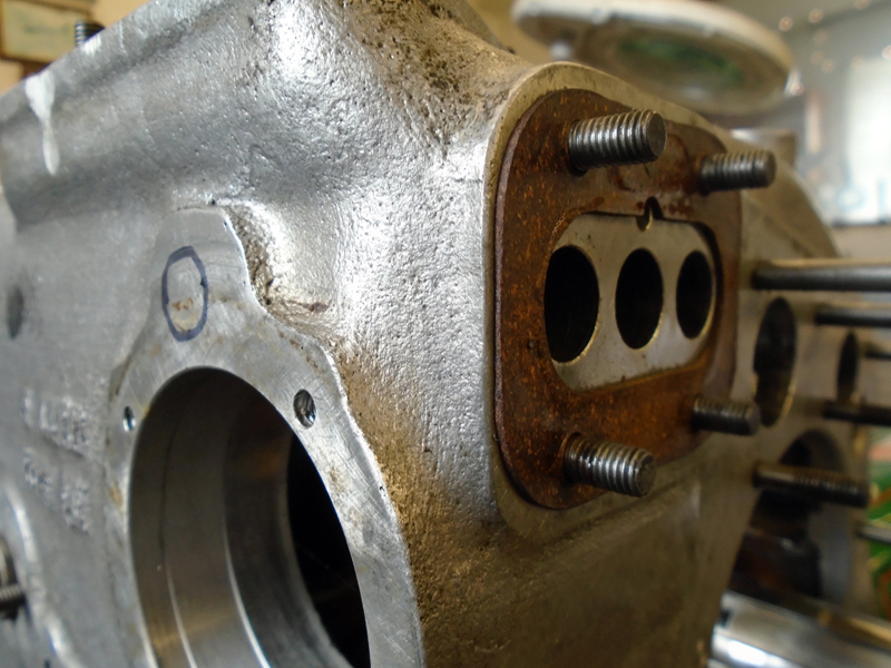 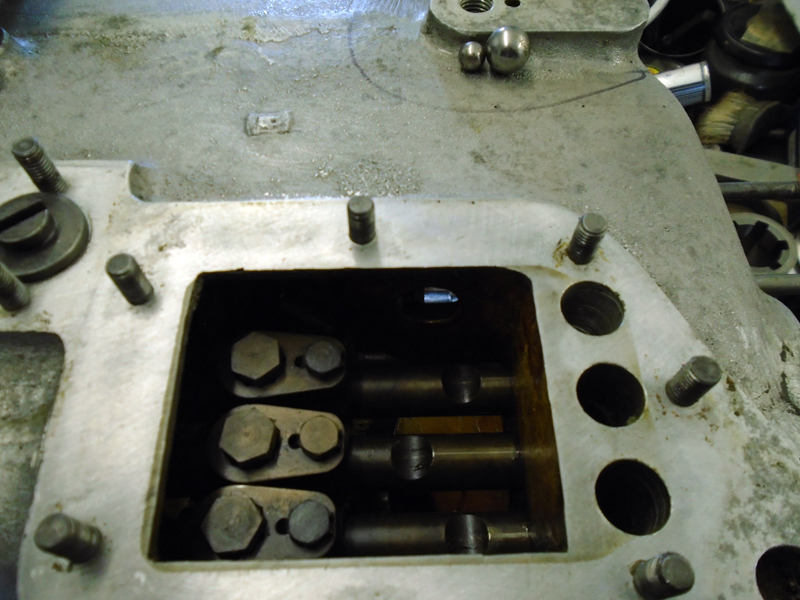 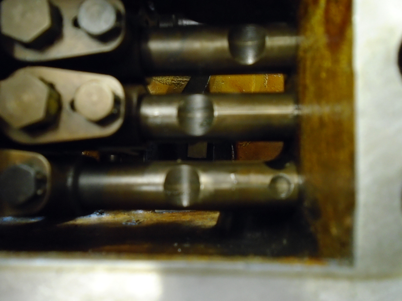 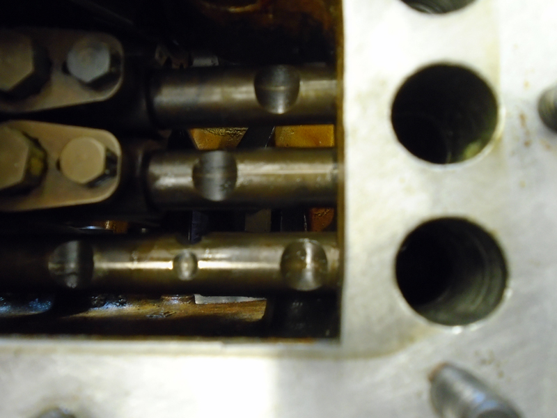 My apologies for any inconvenience this delay might have created. | ||
ChristopherCarnley Unregistered guest Posted From: 5.62.43.175 |
Jeff, On reflection, the next time that I have gearboxes in for work, I shall try your method of removing the reverse cluster to access the forks. It is still a fiddle to get the support shaft in. Chris. (Message approved by david_gore) | ||
Jeff Martin Frequent User Username: jeff_r_1 Post Number: 223 Registered: 07-2018 |
I will post some detailed photos when I fully assemble mine. (this will be early next week when the seals get here). I will make them more detailed then they need to be so there will be many pictures. This is so that someone that whom has never worked on this transmission can do so with out fear. I found the most difficult thing putting back together was getting the pair of springs and balls back into the third motion shaft for 1st gear. When you say "support shaft" are you talking about the reverse cluster shaft or the fork shaft ? | ||
ChristopherCarnley Unregistered guest Posted From: 62.128.217.111 |
Hi Jeff, the fork shaft. The 1st gear is indeed tricky, the way that I do it is to prepare, and try to empty my mind! The balls have to be grease free and you need a long thin flat bladed screw driver. Fit the sliding keys and secure with sticky grease. Fit the springs which can be quite strong for their size, ensure that the gear is the right way round and that the shaft is vertical in the vice, test for fit on the helix to ensure that you are in the right position. Lift the gear up to the first plain part of the shaft from the top, just above the helix. With long tweezers fit the nearest ball, push the gear to compress the spring. Insert the far ball into the gear hole, lower them carefully and feel for the spline. With the screwdriver press each ball into the hole in turn, and slide the key upwards to "lock" the balls into place. Then wind the gear down, fit a Jubilee clip. Then you can turn it round and fit the 3rd speed gear cone and the rest of the selector bits, and another clip. When I fit the servo shaft, the speedo scroll is left off. The shaft is then knocked through, the peg fitted and the scroll is screwed into place, ensuring that the 2nd speed gear arrangement has not been disturbed. The inner half of the bearing inner is then heated up just a little and slipped into place, this ensures that there is no hammering to dislodge the other parts. I have a young chef, who is only part time now working with me, he has a lot of tactile skill (now) but preparing food, which is down the can tomorrow, is not gearbox fitting. He can strip a reasonable gearbox down in 20 minutes, and is well on his way to reassembling one. (Message approved by david_gore) | ||
Jeff Martin Frequent User Username: jeff_r_1 Post Number: 227 Registered: 07-2018 |
My method of installing the servo shaft is a little different, I think I like yours better. I was planning on installing the servo drive after both covers are in place, the third motion will simply turn as its drawn in. It's pretty much all back together, but I tore the rather fragile gasket gasket on the front cover and I'm too lazy to make one by hand _ more waiting. Can't really go any further until I get the cover on. I should have dampened the gasket and ironed it, it was all stuffed into a plastic back, wrinkled and creased. I also discovered that the 4th gear synchro cone can not be put set in place after the second motion shaft is installed. Per photos: To fit the fork into place for 1st and 2ng gear into its lever, the centre support bearing has to be put back in place. As it's eased back into position, the selector shaft must be slid back into the neutral position for 4th and 3rd gear. You will find that the selector shaft has to be moved to get the fork into its lever for 4th and 3rd gear because the whole third motion shaft is forward, see photo "4". 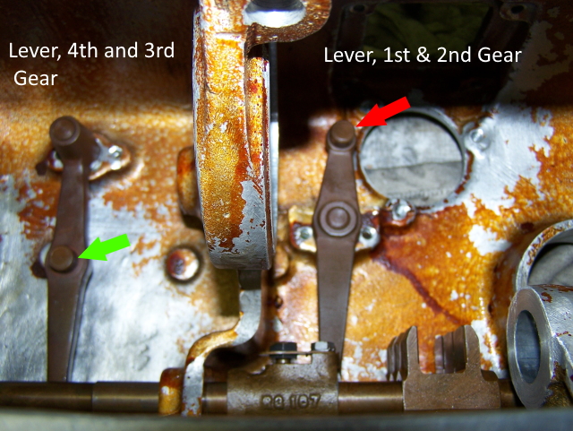  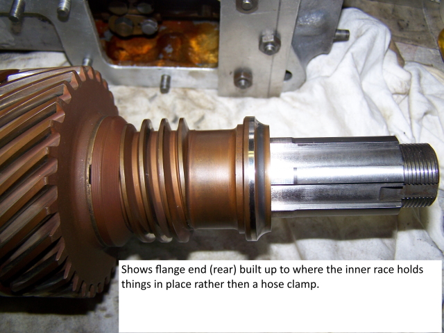 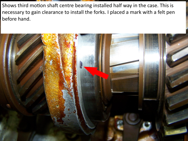 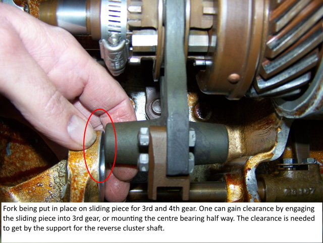 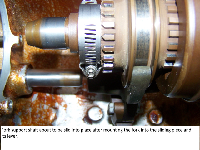  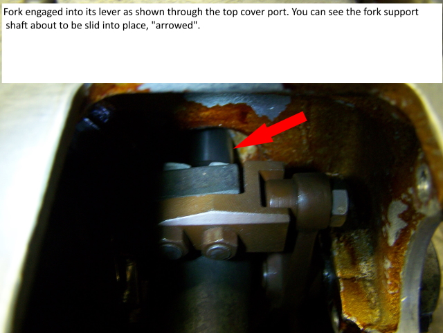 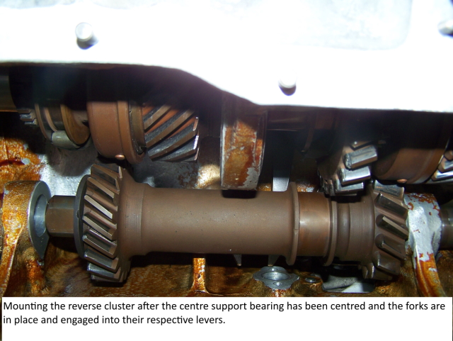 . | ||
Patrick Lockyer. Grand Master Username: pat_lockyer Post Number: 2434 Registered: 09-2004 |
Been watching this thread with much interest, take my hat to you chaps for an eye opening experience of a difficult challenge.Have worked on Meadows and BMC etc boxes but never one so complex as this.One small comment is the maybe worry of the hardening of the gear teeth, what importance if any is it Chris?  | ||
ChristopherCarnley Unregistered guest Posted From: 159.242.227.148 |
Patrick, It is from a forceful down change into 1st gear, this gear should only be engaged whilst the car is stationary. I have had too many examples where where teeth are ripped off whilst slam down changing at speed. One extreme case occurred 2 years ago when the driver of a "new" car from Racing Green Engineering, entering a roundabout from speed, slammed straight into 1st to get a quick exit, ripped 4 teeth off, then ripped 4 teeth from the 12 tooth lay gear, this then ripped another 3 teeth from the 1st gear. Amidst all of the lever thrusting, he demolished the 3 synchro cones. I will try to find the pictures. The gear material is EN39, 4.5% nickel steel hardened and case hardened. The Austin Champ, 11,000 of which were built by Austin has the most complex gearbox, with only 5 forward speeds, and a double constant mesh input. It is rather complex. The rear axle is also complex, again designed by Austin, it is 2 speed and effects the reverse, there is a separate reversing lever by the side of the gearbox. A complete flop, the troops hated them, as there is only the rag top for protection, and the Land Rover predominated. The "Rolls-Royce" B40 designed engine was "simplified for economy" by Austin. There are only a handful of these vehicles left now. (Message approved by david_gore) | ||
BillVatter Unregistered guest Posted From: 73.207.154.68 |
I have been watching this very interesting thread. I have two related questions, but first, the background: I have two gearboxes with different problems: Gearbox 1: This one is original to B340DA, manufactured before the 3rd motion shaft and square-edge bearing modifications. I do not believe the recommended modifications have been made. It has gear-change lever feedback. When decelerating in 3rd speed, the gear change lever pushes back towards neutral, but the gear remains engaged, Apparently, axial force created by the helical gear pattern is pushing third-speed gear forward on the third motion shaft, causing movement of the gear-change fork. Also, when shifting from first to second, if the shift is slow such that the synchro must speed up the second motion shaft to engage second speed, there is unusually high resistance to moving into engagement. If the gearbox is cold, the resistance is so difficult that with the maximum force I think wise, second speed cannot be engaged. Double clutching to speed up the second motion shaft and parts forward makes gear engagement easy. Alternatively, a smart shift (rapidly moving the gear-change lever) works well. However, when shifting smartly, second speed will sometimes grind. Gearbox 2: This gearbox is original to Silver Wraith WGC66, manufactured after the modifications. It has a significant bit of one first speed gear tooth chipped away, and there is significant surface fatigue damage on all of the first speed gear teeth and also the gear teeth of first speed on the cluster gear (second motion shaft). I was driving the car when the gear tooth chip occurred. The gear was fully engaged accelerating in first speed. Suddenly knocking occurred. Luckily, there was no collateral damage. That bit of loose metal made its way to the bottom of the sump without being caught elsewhere in the mechanism. The problems of these two gearboxes suggest to me that one good gearbox could be made from these two that are hurting. I am thinking of taking the cluster gear and first speed gear from gearbox 1 and putting these parts into gearbox 2. My Questions: 1. Will the parts interchange as I propose doing? 2. Will the resultant mating of gears that have not been lapped-together create much gear whine? 3. Do the symptoms of gearbox 1 presented above suggest a catastrophic failure is likely if the gearbox is continued to be used? Any additional comments and/or suggestions are welcome. (Message approved by david_gore) | ||
David Gore Moderator Username: david_gore Post Number: 3934 Registered: 04-2003 |
Bill, You are a registered member of this forum and can post direct to any topic you wish. Your details are below - if you have forgotten your password, it can be reset without difficulty. Just contact me and I will "walk you through the process" if you encounter problems. Bill Vatter Experienced User Username: bill_vatter | ||
Jeff Martin Frequent User Username: jeff_r_1 Post Number: 231 Registered: 07-2018 |
I'm no expert, but in gear box 1, it sounds as if the brass synchro cone is worn like mine and that the oil is too thick. Try changing to Red-Line synthetic gear oil. It almost cured my problem even as burnt as the cone in my trans. | ||
ChristopherCarnley Unregistered guest Posted From: 5.62.43.133 |
I believe that the snap ring holding the rear bearing in the 1st gearbox has broken and the bearing is loose. It is moving forward into the gearbox and jamming the synchronisers. (Message approved by david_gore) | ||
Bill Vatter Experienced User Username: bill_vatter Post Number: 134 Registered: 09-2004 |
Chris, Thank you. That sounds likely. I believe in that specific gearbox (from B340DA) that bearing would be round-edge and likely to have overstressed the snap ring and/or bearing mount in the case. Is more serious damage likely from continued use? What about taking first gear and the multi-gear cluster from that gearbox and putting those parts in the other gearbox that has the bad first-speed gears? | ||
Alexander Lynch New User Username: lex_lynch Post Number: 17 Registered: 07-2020 |
B111 JN 1950 Bentley. So I decided to strip down the gearbox again and fit the strengthened thrust washer RG589 which is 050" thicker than that originally fitted. The third motion shaft was modified by grinding a 23Deg chamfer the front face of the grove with an end float of .002"as per the service hand book.  Washer 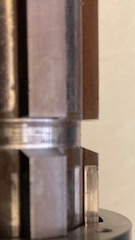 23 degree chamfer 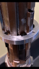 Fitted washer . | ||
ChristopherCarnley Unregistered guest Posted From: 86.137.245.133 |
Alex, Have you ground .050" from the internal shoulder of the 3rd speed driven gear, .050" from the bearing sleeve and .021" from the 3rd speed side of the sliding piece? See Service Bulletin BB 196, in the library. Chris. (Message approved by david_gore) | ||
ChristopherCarnley Unregistered guest Posted From: 86.137.245.147 |
My mistake, I thought that it was the .275" one. (Message approved by david_gore) | ||
Jeff Martin Frequent User Username: jeff_r_1 Post Number: 347 Registered: 07-2018 |
I'm just now installing the transmission, the job was put on hold due to production issues. It was a BEAR removing it, it came out at this very steep angle to clear the "X" in the frame. I thought I could just bring it back at a 90 degree angle, but the rear end of the trans caught on the frame _ did not even come close to clearing it. So to install it, I have the output shaft still disconnected from the trans and temporarily installed in the clutch. This looks like it will allow enough clearance to simply bring the trans up at a 90 degree angle and bring the input shaft assembly to mate it to the trans once it's in the correct position. I still have not installed the needle bearings in the out put shaft _ will do that now with the trans wheeled out of the way. It's just there now to take the photo. 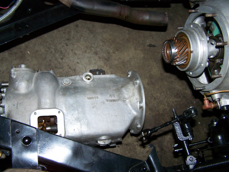 | ||
ChristopherCarnley Unregistered guest Posted From: 217.39.245.69 |
The first question, is, "how will you secure the front bearing housing with the 6 off 1/4" BSF nuts and washers"? Have you checked for gear selection, particularly 3-4, to ascertain the correct orientation of the 3-4 sliding piece. By this method, how will you ensure that the 4th speed synchro cone will not detach? Have you located the black Bakelite assembly aid for fitting the 14 off 6 mm rollers into the input shaft gear, onto the spigot end of the main shaft? The only way to achieve a satisfactory is to install the complete gearbox. On the gearbox subject, I had a call from the fitters at Frank Dale & S.S last Tuesday. Ian was looking for an RG179 second speed (driven) gear for an S1 Continental gearbox. Only 17 chassis were built with manual gearboxes all incorporating the R Type Continental gear trains. So I said that the gear should be RG8000 28 teeth, but they were looking at a mistaken list. Eventually, after asking what the complaint was, noise, and that the lay gear 1st gear had 13 teeth, and both 2nd speed gears were damaged, I told them that at some time, a standard RG179 30 tooth gear had been installed in place of the correct RG8000 28 tooth gear, and buggered the lay gear as well. (Message approved by david_gore) | ||
Jeff Martin Frequent User Username: jeff_r_1 Post Number: 349 Registered: 07-2018 |
That worked well, photos show the input shaft slid back from it's position into the transmission not yet bolted on. The entire transmission ready to be slid forward to mount the bell housing. There was just enough clearance once the brakes servo's alignment pins and the last stud of the service cover was removed. There was room to bring it up at a 90 degree angle. 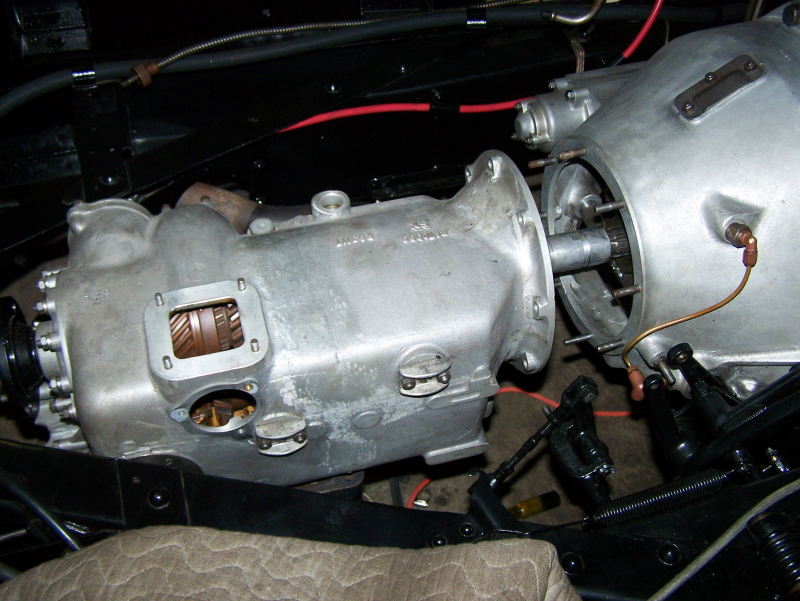 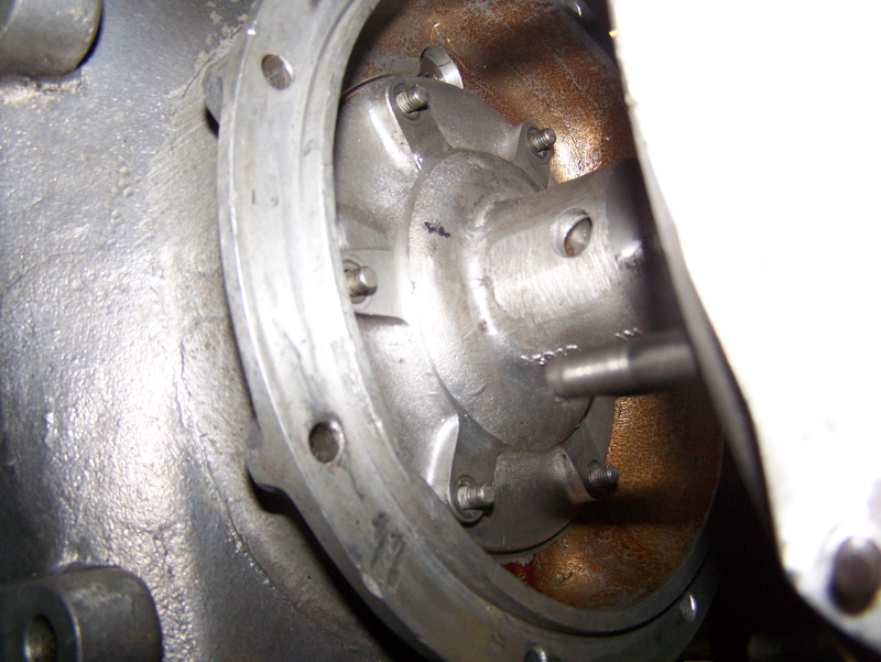 | ||
Jeff Martin Frequent User Username: jeff_r_1 Post Number: 350 Registered: 07-2018 |
The trans is now bolted to the bell-housing, with a little jiggling around and adjustment on the jack, it slid in with this satisfying sound of displaced air. Having the floor out made this job that much easier. | ||
Jeff Martin Frequent User Username: jeff_r_1 Post Number: 399 Registered: 07-2018 |
An update; it's all back together except for the floor, I wanted to start it up and make sure it all shifted properly. The 4th gear synchro cone works again, I'm happy to announce, after such a huge amount of work, I'm a bit relieved. The front yolk on the drive shaft side at the end of the transmission had quite the wobble in it, it was running off centre. Upon inspection, the one bearing cup was not seated home and its snap ring was just sitting on the outside rather then in its groove. It was probably like that since I had the car for the last 20 years, and who knows how long it was like that before. I'm surprised that the snap ring didn't fly out. Who ever worked on it last didn't take the time to assemble it properly, how careless can someone be ??? I suspect the leaky flexible line to the rear shocks caused the failure of the 4th gear synchro cone. The shocks seep, so that's next, in fact all of them need new seals at least. I'm going to drive the car for a couple of months at least, keeping an eye on the oil level in the trans. I have to get a new sump plug as well, as some doofus used a pair of vice grips on it, and now it's distorted and is seeping all the time leaving an oily sump _ can't have that getting all over the servo. A huge amount of time was taken dealing with potential oil leaks from poor design as well. I miss driving it, it's been 2 years, and just recently a phone call out of the blue that a kidney was waiting for me, so that ate another 6 weeks or summer, and I'm slowly getting my strength back from that majour surgery. | ||
Martin Webster New User Username: martin_webster Post Number: 38 Registered: 09-2018 |
Firstly Jeff, I�m glad that the kidney op was successful and that you are recovering well. The gearbox work has been a fascinating insight into how our cars can be rejuvenated using proper machining skills and old fashioned tenacity. Please let us know how you progress in yourself and with the Bentley. All best wishes, Martin |