| Author | Message | ||
John Rowney Experienced User Username: johnrowney Post Number: 43 Registered: 2-2015 |
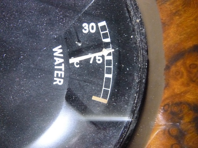 My Bentley Special B25KL has its original temperature gauge. Without having to go through the trouble of removing the temperature sensor and calibrating the gauge, does anyone know what each division means. Over 50 years ago as a small subject in Engineering I studied ergonomics, and one of the things that stuck with me was the importance of having understandable and consistent gauge markings. Obviously this was after 1951 when B25KL was produced. However stupid gauge markings are still made by Audi and Lexus on their speedos. Any help would be appreciated | ||
Christian S. Hansen Grand Master Username: enquiring_mind Post Number: 1005 Registered: 4-2015 |
John... In broad generalities... The Mk6 runs an unpressurized system, therefore its coolant begins to boil at about 100C. That is HOT and the last bar is RED to imply that. You don't get temperatures in an unpressurized system much hotter than that. The lower bar is 30. The upper bar can be assumed to be 100. The middle bar is 75. The other interim bars are just for convenience and signify increments between those three indicated temperatures. That's the way I have always interpreted it. . | ||
christopher carnley Unregistered guest Posted From: 86.176.214.40 |
John, Leave the gauge alone as removing it may disturb the capillary tube and its connections, making the gauge U.S. (Message approved by david_gore) | ||
Norman Geeson Unregistered guest Posted From: 81.99.138.38 |
The following text is a section from an article I wrote for www.kda132.com some years ago. This extract does not contain the graph that is mentioned but I trust the data is self explanation and helpful. Temperature Gauge Calibration To assist in clarifying any results I needed to know on the test car how the dashboard temperature gauge was performing compared with actual coolant temperature. The gauge only has two reference points, at 30C and 75C. An attempt to track down a drawing together with the correct calibration of the gauge was fruitless. Drawing RD 3770-2 dated 29th October 1946, shows the gauge was originally fully marked up with the proposed 30, 50, 70, 90 and 100C positions. The important point to perhaps reference here is that the centre position was 70C, not 75C, as on the current gauges. Also the initial cars were pressurised and even the last of the line could generate 7 psi before the thermostat opened. Drawing RD 3141-3, dated 8th January 1947, shows the dash panel assembly of the gauges and clearly the temperature gauge, marked as the current cars at 30C and 75C. The centre of the gauge position had therefore been raised by 5C, and it is probable that all the marks after the initial 30C starting mark may have been subject to an uplift of 5c, including the highest 100C marker. Although immersing the bulb end of the capillary tube in water across a range of known temperatures should be carried out for true calibration of the gauge, I was not inclined to drain the cooling system off to carry out this full test. I did not want to introduce air unnecessarily into the cooling system, nor finish up with steam pockets in the cylinder head, which may have distorted the road test results. In particular, the water pumps are inclined to hold air in the upper casing for some considerable period after draining and refilling the cooling system. I therefore calibrated the gauge against header tank coolant temperature. The Bentley temperature gauge has nine marked segments, the middle one of which is marked 75C. In order to have an understandable standard I have referred to these marks as A,B,C,D,E,F,G,H and J. The marker A, representing the lowest gauge reading of 30C. Rolls Royce car owners will note that the temperature gauges on the majority their cars are different to the Bentley versions, although the operating principle is the same. The testing routine I followed involved using a digital cooking thermometer as the comparison. First of all, this thermometer was tested for accuracy at water boiling point and found to be within 0.5% accurate. The figures recorded are the comparisons between the car dashboard temperature gauge and the temperature of the coolant in the radiator top tank. This exercise was carried out with the engine switched off and the coolant temperature checked by the digital gauge immersed in the header tank as the dashboard temperature gauge reading fell. The readings were completed after the car had been driven for 30 miles to attain true heat sink of the engine and surrounding components.   It should be remembered that the car temperature gauge is recording the coolant temperature just under the thermostat, whilst the check gauge was recording radiator header tank coolant. Inevitably there will be a differential in temperature between the two points, especially as the thermostat closes. In addition, because the gauge is mechanical, there is a slight delay in the recording temperature of the car gauge compared to the drop in temperature in the cooling system. Actual practice showed the temperature recorded at the header tank was 3C to 6C higher than that noted on the dash gauge. Of course the cooling system was not under pump circulation pressure and it is possible that this differential between the readings does not exist to such a degree in running conditions. Equally some of the differential may be caused by an out of calibration dashboard gauge or a combination of differences. The temperature difference, between the commencement of the mark indicating the normal 75 C running position, and the end of that mark, covered over 3 C (from 78.89C to 82.22C). This shows the scatter and difficulty in obtaining readings even within 3 C. Even so, the readings do provide the driver with enough data to have confidence that the car gauge is presenting the approximate signals. I should add at this point that the rear of the engine cylinder head and block are by far the hottest points on these engines, the actual operating temperature of the engine is therefore much higher than the temperature shown on the gauge. Owners believing that their engine is running within normal temperature parameters can be therefore deluded and fall into the trap of believing all is well. S. H. Grylls, Chief Engineer, Motor Car Division, Rolls-Royce Ltd made this point well in his paper �The History of a Dimension� when he said, � A little moral that can be drawn from this story is always to put the recording thermometer at the hottest part of a cylinder head, a practice which had been forgotten since 1937� At the time of testing it was not possible, due to practical reasons, to test the full spectrum of the operating range of the temperature gauge. I was not prepared to boil the engine for the sake of calibration, for instance. The lower end of the scale is not of particular interest and in any case the thermostat closing masks the header tank temperatures. During calibration, readings were taken through dashboard temperature gauge marks C to F inclusive with extra intermediate readings taken between the gauge marks to provide better results. These extra calibration readings are not reproduced in the graph. The graph in fig 10 shows the C to F readings, together with a computer generated trend line, both above and below, my own readings. For illustration purposes and standardisation throughout, I have quoted the marker readings from the graph trend line. The main reason is that I believe the trend line is certainly not producing a lower reading than actual; therefore accepting this situation is erring on the safe side. Reading at a particular marked letter point on the trend line can be cross referenced to the marks attained when road testing with the high-speed pulley arrangement (on Swiss and Australian delivered cars) described later. The top end marks are a little academic because if the coolant temperatures reach that stage, the engine is indeed in trouble. It is nevertheless interesting that the trend line indicates that the highest gauge mark J is higher than 100C. In practice this agrees approximately with test results kindly forwarded to me by Mr Dick Kress of Ohio, U.S.A who has calibrated the dashboard gauge on his car, an early R type. After testing the capillary bulb directly in boiling coolant of a 50 / 50 mixture and adjusting for the elevation at the test site, he believes the highest possible position on the gauge would be about 108 C. Strange as this may first appear, it is in fact very probable that the gauge was calibrated by the company above 100 C to counter for different cooling system mixtures and the potentially later introduction of a fully pressurised cooling system. Applying a trend line to his readings shows that the two trends are almost identical. (Message approved by david_gore) | ||
Christian S. Hansen Grand Master Username: enquiring_mind Post Number: 1008 Registered: 4-2015 |
John... As Norman has noted, the upper band is academic for if the coolant is running at that temperature (whether 100C or 108C) the engine is in trouble. The reading as in your photo is proper (maybe a smidgeon low) and if an IR thermometer reading of the actual coolant temp (and discounting the problematic issue of circulation to rear of head) confirms that reading, that is all that really matters. If the gauge had no bands or numbers at all and for a properly operating cooling system, a gauge arrow in middle would be "happy" and at the top, "trouble". . | ||
Norman Geeson Unregistered guest Posted From: 81.99.138.38 |
John I have extracted a list from my notes, which may help. This lists the recorded header tank temperature at each gauge marking. These are marked A-J, with A being the lowest mark at 30C. Marks H and J are computer trend readings. A=35C B-50C C=61C D=72C E=80C F=87C G=94C H=101C J=108C (Message approved by david_gore) | ||
John Rowney Experienced User Username: johnrowney Post Number: 44 Registered: 2-2015 |
Hi Gentlemen Many thanks for all your the feedback. I was interested in some accuracy since I was changing over from a Nulon/water 50:50 mix to a soluble oil system (Liquid Intelligence LI600). I normally don't worry about the absolute value of the temperature in my Corniche (DRH32489) since it is always slap bang in the middle of the range and it never changes. I was interested in the absolute measurements in particular, since the MkVI manual says that the thermostat opens at 79 deg C and is fully open at 95 deg C. Christian: The photo was taken of the gauge after the car had been garaged for a while, and had cooled down, hence the appearance is somewhat low. Chrisopher: Great advice on leaving the tube alone. This advice, I am sure, has saved me considerable angst if I had damaged the tube. (My old man called me a ham-fisted bastard). Norman: Many thanks for the details of your measurements. what a lot of effort you have saved me. I can now better envisage how my coolant system works. Under "normal" running, B25KL now runs at about 85 deg C based on your figures, which would mean that the thermostat would still have a fair way to open at that temperature. When I designed fluid piping systems about 40 years ago, we generally aimed to have control valves about 40-60% open at normal operating conditions. This would seem to be the sort of thing that the thermostat designer may have had in mind when he designed this sort of circuit. ie when needed, there is a lot more ability for the thermostat to open further to get more flow through the radiator. With the thermostat fully open at around the "G" mark it all makes sense. As an additional note, the LI600 worked fabulously well for a trip to Toowoomba at the weekend. At about 100kph on the straight, the temp sat normally even with the ambient temperature being around 41 to 42 deg C at Gatton yesterday. | ||
Christian S. Hansen Grand Master Username: enquiring_mind Post Number: 1015 Registered: 4-2015 |
John... Have you considered getting a quality (about $40-$50US) infrared thermometer and using it to check/verify temperatures at various places around the engine bay? at thermostat, top of radiator, various areas in radiator (should be cooler as you go down I presume), bottom return, various places along the head. It is interesting to witness how temperatures change widely in various places. This should give you an idea of how "your" engine is responding depending on its unique age, wear, coolant, flow, sedimentation, et cetera. When out of the factory, I would bet the engines were all widely similar in terms of cooling performance, but after 60 years of varying circumstances, I bet coolant performance is all over the place (you know it is!). Some engines habitually overheat, some do not. You should graph your engine for comparison to an ideal. Just saying. . | ||
John Rowney Experienced User Username: johnrowney Post Number: 45 Registered: 2-2015 |
Christian: Yes, I have got an infrared thermometer and have used it when I had problems with the temperature gauge on my Corniche. I replaced the gauge and sensor unit after finding all temperatures were normal when the gauge showed zero. I am just a slack old bastard who has a lot of jobs to do on my 3 poor old classic cars, and some things I just never get around to unless they become critical. At times I think I have done enough and then go surfing instead. Perhaps I will do something like that................tomorrow. People like me are called a gunna. | ||
christopher carnley Unregistered guest Posted From: 86.161.255.78 |
"Am, gunna put t,guzzunda unda"! (Message approved by david_gore) | ||
Norman Geeson Unregistered guest Posted From: 81.99.138.38 |
John Given that you are concerned about temperatures and the car is running in ambient temperatures of 40C + I would suggest you consider fitting a high speed water pump pulley. These pulleys (RE 19043) were standard fitting on Australian delivered cars at the time your car was produced. Should you decide to make up one locally ensure that the inside of the pulley clears the bypass port casting by at least 0.20 inch. These pulleys have the advantage of passing a larger volume of water to the rear of the engine besides speeding up the fan���.both advantages in traffic. Keep in mind that according to Rolls-Royce�s own tests the engine runs 13C degrees hotter at the rear than at the point where the gauge is sensing!! There is also a strong case to support arranging for a coolant return from the rear side of the cylinder head to the water pump inlet to encourage rear end coolant flow. The company used this through flow arrangement on a number of military engines and even managed to run long term tests with engines at a constant 100 C outlet temperature. In the case of the EPW six cylinder engines any rear end to coolant pump return needs an internal restrictor of 0.250 inch (6mm). Other options you have are fitting a six blade fan of the type used by Classic Air in Florida USA, (this assists in holding back fuel vaporisation from personal experience). In addition fitting a fan shroud has advantages at slow speeds and with some research you would find this, and some methods mentioned, was used on Royal procession cars. In relation to thermostat opening temperatures they are very dependent on the particular coolant pump efficiency, pump speed and type. An alcohol type stat starts to open way before its rated opening point under system head pressure. Manual after manual will provide a description of testing a thermostat in hot water but this has no accurate bearing on the true operation, a very loose guide that users take as gospel. On test bed engines fitted with coolant flow viewing plates in the block, and at the thermostat, it can clearly be seen that alcohol thermostats lift early. The weakness of these thermostats under running pressure conditions was one reason for a change to wax type units, however even those early wax ones suffered from the same problem. I would be interested in knowing more about your coolant mix because I have never used automotive anti-freeze in a personal car of my own for years, and have no intension of doing so. No self-respecting plant engineer would ever consider using automotive antifreeze in a valuable industrial water plant, so why would I put it in my engine? (Message approved by david_gore) | ||
Larry Kavanagh Prolific User Username: shadow_11 Post Number: 283 Registered: 5-2016 |
Very interesting reading Norman. I would like to enquire as to what coolant you use? | ||
John Rowney Experienced User Username: johnrowney Post Number: 46 Registered: 2-2015 |
Norman: Many thanks for the further info. 4 years ago I replaced the radiator core of B25KL with a modern design core and installed a modern 6 bladed fan. 2 years ago during an extensive restoration, I installed an electric fan at the front of the radiator which is switched on manually when the need arises. Since I have made these changes, and am now happy with the car's cooling performance, I think I will defer the suggestion of increasing the water pump speed by changing the pulley size - well... just not yet. Perhaps in the future? The coolant I now use instead of a 50:50 mix of Nulon and water is a soluble oil which is a 50:50 mix of Liquid Intelligence LI600 and water. The soluble oil mix has very similar thermal properties to water, and its performance reflects this fact. I now can run from the Gold Coast to Brisbane on a hot day (a relatively flat run) without using the electric fan. In the past, the fan was normally used to avoid high temperatures. Details of the LI600 can be found on www.liquidintelligence.com.au This morning I looked at the temperature near the temperature probe using the IR thermometer, and it was close to the value given in Norman's calibration. Very comforting information. A few months ago, I trialled LI 600 on my 1938 Wraith (WXA68) after a disastrous usage of Evans Waterless Coolant. I was really happy with the soluble oil, so I then used it in B25KL with similar pleasing results. | ||
Christian S. Hansen Grand Master Username: enquiring_mind Post Number: 1020 Registered: 4-2015 |
I am prone to being easily confused so please indulge me. First: Regarding the rear of head to water pump coolant line, where is it best tapped to the head and how connected to the water pump inlet? Is there a past article (KDA132 website?) that I have missed? I would think the modification to be SOP and prudent. Second: If additional flow from rear of head to water pump inlet is desirable(essentially "sucking" coolant to the rear of head and then back to pump) I would think the more flow the better, so why restrict it with a .25" orifice or similar sized coolant line? . | ||
David Gore Moderator Username: david_gore Post Number: 3080 Registered: 4-2003 |
Christopher Carnley has requested I post the following comment and photograph on his behalf: "He decided not to use automotive antifreeze". I sent him on his way with a good second hand one, only replaced with a new alloy type as the client wanted high compression pistons. 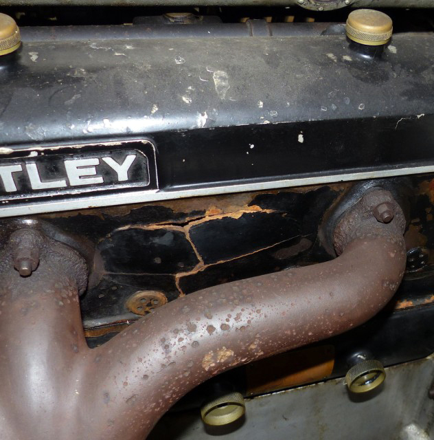 . | ||
Martin Cutler Prolific User Username: martin_cutler Post Number: 238 Registered: 7-2007 |
Bit of devcon and she�ll be right mate! | ||
christopher carnley Unregistered guest Posted From: 86.136.23.209 |
 (Message approved by david_gore) | ||
Norman Geeson Unregistered guest Posted From: 81.99.138.38 |
Christian Q��Regarding the rear of head to water pump coolant line, where is it best tapped to the head and how connected to the water pump inlet��� The usual way is by tapping into the most rearmost core plug on the exhaust side of the cylinder head. It is best to drill the plug and tap rather than trying to extract the plug. There are a number of ways of connecting to the water pump inlet depending on the pipework furniture used on the car. For instance late cars are fitted with Continental heaters and the return joint can be adapted, as can the normal heater return pipe, some are fitted with heater drain taps that can take an adaptor. On all cars it is possible to cut the bottom hose and insert a �T� section to accept a return fitting; in fact you are spoilt with the choice of potential return tappings. Q�.�If additional flow from rear of head to water pump inlet is desirable(essentially "sucking" coolant to the rear of head and then back to pump) I would think the more flow the better, so why restrict it with a .25" orifice or similar sized coolant line? An open flow would prevent correct cooling as the radiator would be by-passed with large amounts of coolant flowing from the rear of the head to the water pump inlet. An open flow system would also rob the water pump of its full pressure ability to circulate coolant around all parts of the engine. This rear end flow is desirable only to even out the different coolant temperature gradients throughout the engine, stop localise rear end boiling and dispense air pockets. The restrictor allows the advantages without the disadvantages. This modification has the advantage that it can be completed with the engine in situ without too much trouble. A similar, but better result can be achieved if the cylinder head is removed. In that instance the coolant passages between cylinder block and cylinder head on the exhaust side only can be blanked forward of the ignition distributor. This forces more coolant around the rear of the engine and when used with the external coolant by-pass to the water pump works well to damp out hot spots. This system has been used successfully to my knowledge since at least 1962. Some years ago Lloyd Missen from Sydney successful rigged up his Silver Dawn with thermocouples and proved the advantages of the external coolant bypass system. He used the car successfully on the Australian Overlander trips, but last time I saw the car is was fully stripped in his living room!! An Australian thing I think to keep out of the sun.<smile> (Message approved by david_gore) | ||
Christian S. Hansen Grand Master Username: enquiring_mind Post Number: 1041 Registered: 4-2015 |
Norman... Thanks for the detailed response, but I still misunderstand. Perhaps I am overthinking it but it seems to me that better flow to, around, and from the rear of the engine/head would be desirable but you indicate that it is limited by these two downsides cited: 1) An open flow would prevent correct cooling as the radiator would be by-passed with large amounts of coolant flowing from the rear of the head to the water pump inlet. 2) An open flow system would also rob the water pump of its full pressure ability to circulate coolant around all parts of the engine. I can grasp that flow from the rear of head directly to water pump would bypass the radiator and perhaps actually cause increased heat rather than less. I do not so much grasp the issue of reduced water pump pressure to other parts of the engine unless by that you are meaning that the flow pattern takes the easiest route and that "without" the rear bypass, the easiest route does not provide sufficient flow to the rear but "with" the rear bypass (open flow) the easiest path is to the rear (and back to water pump) and that other parts of the engine then become hotter due to reduced flow to those other areas. If this is so, then I do not grasp why blanking off the flow paths at the front would be good since you would be in effect further restricting flow in those areas...unless the two systems are NOT to be used together. That is, if you use the external bypass, DO NOT blank off the forward areas but if you DO NOT use the external bypass and have the head removed, then blanking off the forward areas is the preferred method. Expressed another way...the external bypass is simply a work around in lieu of removing the head and blanking off forward areas, but is not to be used in conjunction with the blanking method. Another variant of this question: Are you suggesting that TOO MUCH flow to the rear is not good since it serves to create a convenient exit path and thus divert flow that would otherwise go elsewhere? If so, then it seems to me that the main problem is that the engine flow design simply has crappy characteristics and it becomes a choice of the lesser of two evils. i.e. where do you prefer the flow to go, but you can't have it go everywhere. What I am thinking is this: What if you designed an external bypass going instead of to the water pump, back to the upper hose from thermostat housing to radiator? Yes, now you are bypassing the thermostat but that only matters when the engine is warming up. If you installed an "on-off" tap into the line, you could leave the bypass closed until engine warms and then variably open it to get flow to the rear of block depending on engine temperature. Under this scenario would you be creating the "path of least resistance" flow that would rob flow to other areas of engine causing those areas to heat, or would it be better for the entire engine to have the flow to the rear and then to radiator rather than back to water pump? . | ||
Norman Geeson Unregistered guest Posted From: 81.99.138.38 |
Larry I have used an industrial antifreeze and protector for many years, mainly because of my experience with large industrial water plants that require metallic corrosion and rubber protection. Often these plants are running on the extreme edge of temperature control with far higher demands than the automotive cooling systems. For instance, the last plant I covered was rated at 100 tonnes per hour , that is the ability to make 100 tonnes of ice per hour whilst resisting corrosion on all normal industrial metals. Of course the weir coolant flows must not freeze under any operating conditions. Although car owners or garage owners may not want to avail themselves of such a high coolant protection level, the corrosion protection and antifreeze ability is on a different planet than automotive antifreeze. Some years ago Derek Harris of the RREC wrote an article on antifreezes and corrosion protection in particular the use of Fernox Alphi 11, a similar product to the one I was using. This had an advantage in that it was cheaper, available Worldwide and exceeded all the current BS (British Standards) for automotive antifreezes. I changed over to Fernox Alphi 11 at that time, I guess over 25 years ago. (Message approved by david_gore) | ||
Martin Webster New User Username: martin_webster Post Number: 7 Registered: 9-2018 |
I have never had any issues with a 50% solution of good old fashioned Bluecol in my former ownership of a Cloud 11 or my present H series Mk VI. Summer and Winter temperature parameters always within limits and no leakage. Flush out and refill every two years with no fuss. |