| Author | Message | ||||
Nick Brough Unregistered guest Posted From: 81.76.126.80 |
Hi, I have just bought a 1931 Rolls 20/25 and she is a reluctant starter can anyone advise me of the correct procedure for starting. Also, I cannot seem to change down without crunching the gears. On my 1935 Brough Superior I simpley double de clutch quickly and give a short blip on the accelerator during th process. Do I need a different technique for the Rolls. Any advice would be gratefully recieved. Thanks Nick | ||||
Patrick Lockyer. Grand Master Username: pat_lockyer Post Number: 177 Registered: 9-2004 |
Hi Nick. If the car has been used recently procceed by first turning the fuel on with the tap on the dashboard to "m" or main. There are two other positions will say about the later! Next turn ignition switch "on" to the right to the "I and c". Make sure the gear lever is in nutral and the handbrake on. Set the thumb lever on the dash to start.[Strong on early cars] Fully retard the ignition and move the hand throttle half way up the quadrant. The starter button can now be depressed not sure if it is starter pedal or button. Should fire up almost stait away. When warm move lever to Normal. When engine is fully warmed up move lever to Run. If it does not proceed to start as above then we must look at other points. From memory the other tap positions are "r" reserve 2.5galls. "O" fuel off. On the gear box side you just misted the syncromesh box that came in on chassis no GKT 22 1932. My advise is double de clutch and change gear briskly As you are doing with that spendid bike that you have. A novice "sorry" will soon be experenced with practice! I can put some pix of a 1929 twenty with Auto vac and the manualy operated vertical rad shutters,and a folding rear back body of progessing stages of restoration over the comming months. | ||||
Nick Brough Unregistered guest Posted From: 84.65.51.144 |
Pat, Thanks for the info, the Brough is actually a car not a bike. They built a few she is one of the few 8 cylinder models. They used Hudson 8 running gear. Nick | ||||
Stephe Boddice Unregistered guest Posted From: 84.67.63.158 |
Nick, The 20/25 had several variations of the carburettor fitted during its production life - all being of the same basic design. Rather than using a choke flap these Rolls-Royce designed carburettors incorporated a 'starting carburettor' within the main body of the unit. The starting carb is identified by a knurled screw, held by a lock nut, protruding vertically from the top of the carb adjacent to the float chamber lid. Adjustment is required for climate/temperatue. Slacken the lock nut, turn the screw down (clockwise) until it closes the jet - use finger pressure only - and then unscrew by between 1-1/4 and 1-3/4 turns; tighten the locknut. The further out the adjusting jet is turned the richer the mixture. If you are in a temperate climate you should need only 1-1/4 to 1-1/2 turns. When the starting carb is correctly set the hand throttle should be FULLY closed when starting from cold - otherwise the engine will not start. As the starting carb is released the hand throttle should be opened. The starting carb should be completely closed off withing a maximum of 30 seconds from ignition - even in the coldest of conditions. Regarding the advance/retard lever - this should be set at half way. Full retard on starting should only be applied when using the starting handle with magneto ignition. All other instructions are as per Patrick Lockyers posting. The gearbox should be lubricated with SAE30 or a mineral multigrade of 20w50. These gearboxes do take some time to warm up; gear changing is much easier once the oil is hot. Standard double de-clutching will then work. Make sure that there is adequate free-play on the clutch pedal when in the released position. There is no pedal-return spring on the 20/25 so it is important that there is at least 1/2 an inch free movement when the floor boards are in position - otherwise you will suffer terminal clutch slip. Hope that this helps (rather than confuses) Stephe Boddice (20/25 GGA27 & PIII 3CP196) www.boddice.co.uk | ||||
Patrick Lockyer. Grand Master Username: pat_lockyer Post Number: 193 Registered: 9-2004 |
Stephe,Your instructions are certainly not confusing the issue it is myself that has! I had always found that in most cases the car will start from cold on the starting carb ok,the problems in most cases arose once the car had been used recently and then failed to start. And there are many starting related items that can cause the faults. I have seen[i won't say heard as the starters are so quiet]many engine being wound over before some finally fire up. Do you still use the fine gauze strainer on the carb inlet to the float chamber. Does the block condenser,capacitor fail on the passing off time. How about the bakealight coil tower the distributor cap and the rotor arm failing. And more! | ||||
Patrick Lockyer. Grand Master Username: pat_lockyer Post Number: 199 Registered: 9-2004 |
To interested folk. Why do these cars start so well from the first start of the day on the starting carb and then can be so contrary. well one of the problems can be the rotor arm. It is only after the engine warms up do they seem to break down and short out. But why? could it be the bakalite expands or just old age. 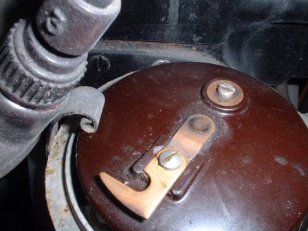 | ||||
Stephe Boddice Unregistered guest Posted From: 84.65.131.88 |
Patrick, I have only just picked up your comments - sorry for the response delay. You are quite right to point out the other areas that cause problems with starting. It's good to see that the contact arm in your photograph is the right way round - ie. pointing in the direction of rotatio. It is possible to fit these backwards and retard the ignition by about 15 degrees! Commenting on 'warm' starting problems: - 1) It is not common (though not unheard of) for the Bakelite of the rotor arm to crack. If the crack goes through to the distributor shaft then electrical shorting can take place with the obvious problem of no ignition spark. 2) The usual suspect for problems during warm starting, and also during driving once the engine warms up, is that the coil insulation has broken down and the ignition shorts out. If this happens, try shorting out the ballast resistor. If the engine starts then you can guarantee that the coil is shot. The original type coils are all but unobtainable although you may be lucky and find someone who can re-wind it correctly. This is a subject in its own right as the factory even managed to do it back to front on several occassions. The best bet is to fit a new modern 12 volt coil in the old carcass and run the ignition with the ballast resistor shorted out. 3) The next suspect is the condensor, which will break down with time. These are available from the usual R-R suppliers and have the correct rating. If you have swapped to a 12 volt coil it is preferable to get a condensor with a matched rating. 4) Another useful check on the distributor is to make sure that the contacts are clean inside the cap. If you are handy with a vernier gauge you can also measure the diametric clearance of the rotor arm with the cap contacts. Another area of failure is if you have a repro cap where the contacts are slightly higher in the cap body than original - check the hight of the rotor blade relative to the cap contacts. I found on one of my cars that the rotor was spinning about 1/16" below the contacts - so I had to measuse and then bend the rotor arm upwards until it was in the correct alignment. 5) A final problem with failure when driving is fuel starvation. This is usually put down to evaporation in the Autovac due to its proximity to the exhaust manifold. The reality, on these pre-war cars, is usually a build up of solid fuel varnish on the petrol filter. No amount of washing with petrol or solvents will remove this varnish. What actually happens is the varnish blisters, as the filter heats up, and closes off the gaps between the disks, which were only 0.002" wide originally. The answer is to dismantle the disks and soak them in lemon juice for 24 hours. This disolves the residue without damaging the metal disks. Just a few more problem areas to check out. Stephe Boddice (UK) www.boddice.co.uk | ||||
Patrick Lockyer. Grand Master Username: pat_lockyer Post Number: 231 Registered: 9-2004 |
Stephe, many thanks for your excellent interesting reply. Must confess we use the oscilloscope for the avalible voltage coil output and secondrary insulation faults present. The condenser is ok on the scope, but would like to know what the capacity mfd should be from a new one. Never thought of the lemon juice trick with the disks. Pix enclosed of the condenser looks original? 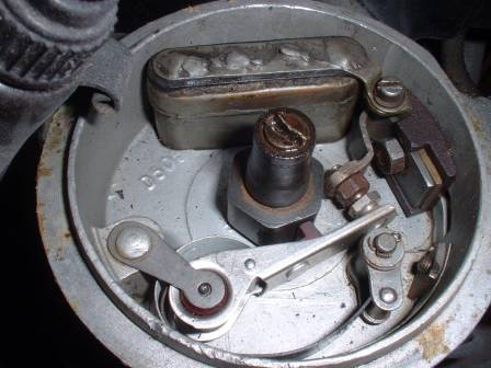 | ||||
Stephe Boddice Unregistered guest Posted From: 84.65.131.88 |
Patrick, You will have to be patient on the condenser capacity rating. I have got the info somewhere but cannot put my hand on it at the moment. I will let you know ASAP. The unit in the picture is an original and very rare - you won't get one of those at the local auto-shop. Stephe | ||||
Patrick Lockyer. Grand Master Username: pat_lockyer Post Number: 237 Registered: 9-2004 |
Hi Stephe. More progress. Today i took the tank petrol pickups and the gauge sender unit out. There are two strainers one main and the other reserve,both partly clogged this would cause petrol starvation on full throttle up hills etc could easly be overlooked. Checking the dash level gauge it seems to have two pipe conections but there are three there leading to it?[behind dash] I have not worked out how it all works yet as i did not take it apart. The body has new wood where needed. Fitting the panels up before the trimming is a must, no good to alter things after. The doors have cross tentioners to line the shuts and to rectify any twists. Rear wings have pipeing and are temp fitted as are the running boads front wings and doors. 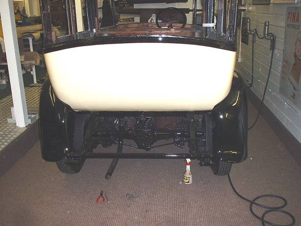 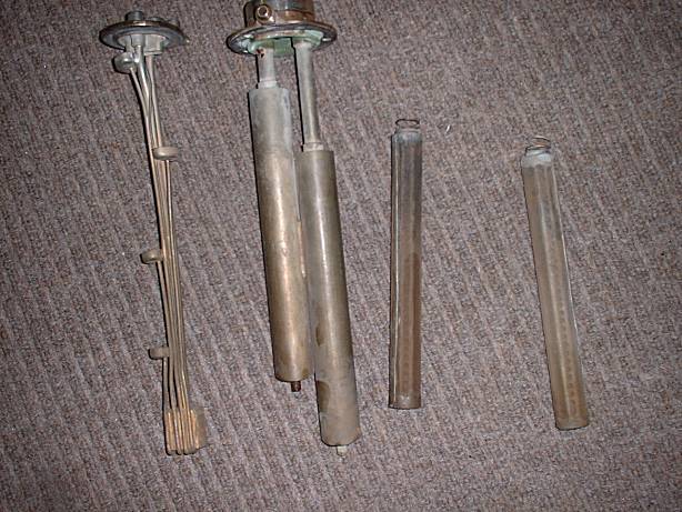 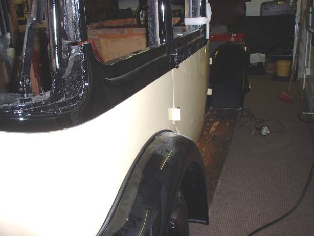 | ||||
Stephe Boddice Unregistered guest Posted From: 84.65.131.88 |
Hi Patrick, An interesting looking car. What chassis # and coachbuilder? Regarding the fuel sender and gauge - this is the Hobson K-S "Telegage" Fuel Level Indicator, to give its correct title. This a hydrostatic level indicator that works by air pressure working against a fluid in a 'U' bend inside the gauge. The liquid was comdemned years ago as being highly carcinogenic - so be careful. If you can get hold of a copy of the combined Owners Hanbook for the 20/25, produced by the RROC in 1964, there is a full explanation of the set-up. The RROC of Australia probably still stocks it. If not, I could copy the relevant bits and sent it to you in PDF. Let me have your e-mail address if you need the info. Stephe | ||||
Patrick Lockyer. Grand Master Username: pat_lockyer Post Number: 239 Registered: 9-2004 |
Thanks Stephe,will be in touch with info. | ||||
Patrick Lockyer. Grand Master Username: pat_lockyer Post Number: 241 Registered: 9-2004 |
Stephe many thanks,i now know how it works the problem is the air pump as you suggested,that is what should be on the third connection. It is missing,a hunt will be underway tomorrow! | ||||
Patrick Lockyer. Grand Master Username: pat_lockyer Post Number: 251 Registered: 9-2004 |
Petrol pickups and level tubes fitted with the tank fitted in place, the luggage frame not complete is fitted. The spare wheel was attatched to it at some time in its life, with a tool box mounted on the correct bracket for the spare on the n/s. The spare will be positioned n/s with a new luggage box made to fit the frame. 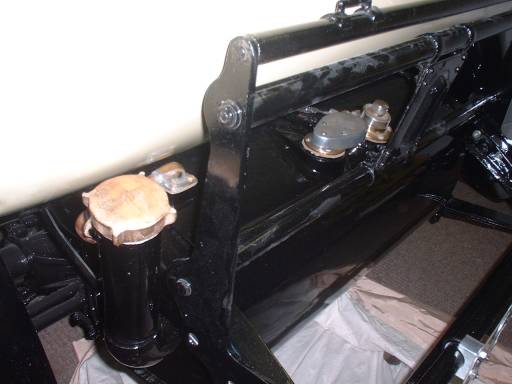 | ||||
Stephe Boddice Unregistered guest Posted From: 81.77.76.147 |
Patrick, In reponse to your question of 16/1 - capacitance of ignition condenser - the following is a summary of an article in Tech Manual #4 (RREC) written by M Watford. Pre-war R-R ignition coils were constructed to run at 4 volts and have resistance of 1.5 ohms. The ballast resistor should be rated between 3.0 and 3.5 ohms. When correctly wired, there should be a resistance of 0.5 ohm between the ballast resistor and the coil. Recommended condenser ratings: - Original 4 volt coil 4.7 mfd Modern 8 volt coil 3.3 mfd Modern 12 volt coil 2.2mfd If you cannot get hold of a 4.7 mfd capaciter the alternative is to use two 2.2 mfd items connected in parallel. I knew I had the information somewhere. Stephe | ||||
Patrick Lockyer. Grand Master Username: pat_lockyer Post Number: 267 Registered: 9-2004 |
Stephe, thanks for your help. Pat. | ||||
Patrick Lockyer. Grand Master Username: pat_lockyer Post Number: 270 Registered: 9-2004 |
Running boards completed,next glass removal and new made in safety glass. What winding mechanism pix in due course. 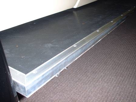 | ||||
David Gore Moderator Username: david_gore Post Number: 380 Registered: 4-2003 |
Pat, Very regular progress on this - how do you find the time and avoid conflict with the "domestic engineer" in the process? You will finish up with a very attractive and desirable motor vehicle. | ||||
bobclarke Unregistered guest Posted From: 202.67.65.166 |
I refer to data given on condensor capacitance is doubtful. Original 20hp chassis cards of specific cars state the following values: Chassis 42G1: 0.330mf; Ch 45G2: 0.310mf; Ch 67H8: 0.298mf; Ch 75A8 was 0.325mf; 77A5: 0.275mf; GPK47: 0.282mf These cars had the same coil specs as early 20/25. i replaced the interior of an original condensor on my 1927 20hp about 10 years ago with the following capacitor from Dick Smith 0.3mf @ 400volts. the 400volt is required for spike voltage. I investigated GMH, CHRYSLER & FORD literature at that time & found they used 0.18-0.25mf; 0.25-0.28mf and 0.28-0.31mf respectively. A lot of the original condensors are earthed thru the spring clip holding it in the distributor, with wear, the distributor can have a poor earth. regards bob clarke 20hp Registrar Aus | ||||
Stephe Boddice Unregistered guest Posted From: 81.79.0.29 |
Response to Bob Clarke - condenser capacitance: - The information supplied a few threads ago was lifted straight from Technical Manual #4 from the RREC. Although I cannot vouch for its accuracy the article has never been refuted, which would definitely be the case if incorrect information had been presented. Furthermore, the full transcript of the original article contained a set of calculations supporting the results that have been summaried above. Regarding the comments relating to specific 20HP cards: - I have no desire to argue with the statements made. All of the chassis numbers quoted are from the very early series of this model. Having checked the few chassis records in my possession, covering 20/25, 3 1/2L B, PIII & Shadow, no chassis card shows the capacitnce of the condenser; only the part number and the actual part reference number as fitted to that particular chassis. I have also checked both of the published R-R parts lists for the 20HP (1924 & 1928) and neither give a condenser rating. Moving on to the comments on GMH, Chrysler and Ford literature: - It must be assumed that this information was generally post war and pre-electronic. The following comments being made from memory due to a lack of literature to hand. These companies used a mixture of 12v, 8v and 7v coils, dependent upon model and year. Arithmetically, all of these figures support the use of the capacitance figures quoted. Rolls-Royce adopted 4 volt coils for the specific purpose of protecting the coil in the event of the ignition switch being left in the 'On' position. The ballast resistors are rated at 3.0 ohms. I have not had chance to look up the date of the implemention this system but assume it to in about 1922. If the car is correctly wired to original specificatoin then it should show approximately a 3 amp charge when being driven. The other test of correct set-up, and correct capaciter, is the ability to start a warm engine by switching on the ignition and then moving the advance/retard lever from retard to advance. SB 20/25 & PIII www.boddice.co.uk | ||||
bob clarke Unregistered guest Posted From: 202.67.65.166 |
stephe i would suggest the info in Watford's article on capacitance has been put in question with at least 2 letters to the editor about the values stated- probably in following issue of Bulletin. I suggest the decimal point is in the wrong location in Watfords article which was published in B153/33 and should read 0.44mf etc (Message approved by david_gore) | ||||
Phil Sproston Unregistered guest Posted From: 203.166.249.78 |
For points and condensers just remove them and replace with a electronic system. I have just bought a system from Dennison-Jayne Motors in West Chester PA USA (610-436-8668) which they make by fitting a Pertronix unit to a new rotor assembly. They also supply coils to suit the this system. Don't forget modern fuel is not designed for these older motors. If you want to replace the distributor cap ATH Alden Limited UK (020 8531 3358) make a very high quality cap, except they do not supply a carbon brush and spring, so back to Ristes Motors for those parts at 4.40 pounds each. GBA1 20/25 (Message approved by david_gore) | ||||
Robert Wort Grand Master Username: robert_wort Post Number: 187 Registered: 12-2004 |
Hi Pat, Time to stir up the hornet's nest. What's the latest with this old lady? Any more work done recently? Rob  | ||||
Patrick Lockyer. Grand Master Username: pat_lockyer Post Number: 442 Registered: 9-2004 |
Hi Robert, time to start again on the old girl in a couple of weeks all being well. | ||||
Robert Wort Grand Master Username: robert_wort Post Number: 219 Registered: 12-2004 |
Now this is something I'll definitely be looking forward to. | ||||
Patrick Lockyer. Grand Master Username: pat_lockyer Post Number: 445 Registered: 9-2004 |
Things have slowed but will get going again in the fall. Just not happy with the dash so its all out and a new one is being made. All the the glass is being renewed as well. 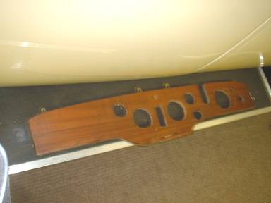 | ||||
Robert Wort Grand Master Username: robert_wort Post Number: 235 Registered: 12-2004 |
I've been a bit slow on the response Pat But I'm glad to see things back on track with the old girl. I look forward to further installments. Cheers, Rob | ||||
Patrick Lockyer. Grand Master Username: pat_lockyer Post Number: 471 Registered: 9-2004 |
Been a little time since working on the old girl. That dash just did not look right. So walnut veneer laid useing the original dash. It is not April the first but the final process is with a orange flamed blow torch.[two pack lacquer] Painting and spraying lacquer ir the old way, flating after each coat is dead never again paint rub paint rub----. I believe this new way came from the USA it is so much better but one thing the surface has to be dead leval for the flow. All the glass [lamenated]is renewed and will be refitted in due course. Pix of the completed dash,hope others look the same,will not change it now,next all the other capping etc to match. My word what would we do without pictures on this site. 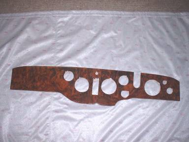 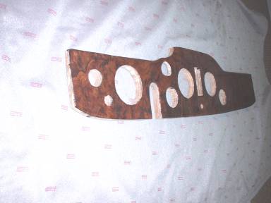 | ||||
Stephe Boddice Experienced User Username: stephe_boddice Post Number: 24 Registered: 2-2005 |
Pat, Nice to see that you are back working on the old one. Was the new glass cast to pattern or cut from sheet? If the former, I would check dimensions before you start fitting to avoid disappointment. SB | ||||
Bill Coburn Moderator Username: bill_coburn Post Number: 557 Registered: 4-2003 |
Pat/ You don't have much option but are you aware that laminated glass should not be used in movable locations? The correct glass is toughened. The reason, I found out the hard way, is that the latter is to some extent flexible. If the door with laminated glass is slammed and the glass is say half way down in the frame, the top of the sheet flexes and cracks. The laminate of course holds all the bits. Toughened glass (the stuff that breaks up into many bits that you can never get all of them out of the car after a breakage)flexes and doesn't crack. But apparently toughened glass has to be made to shape and can't be cut so you are stuck with laminates for the side glasses and you should carry a basball bat for those passengers that slam the doors! The windscreen being supported all round rarely gives any trouble except in coachbuilt cars with fairly floppy bodies. With these cars it is imperative that if you are crossing a road hump that you go over squarely. A diagonal manoeuvre, the body and screen frame twists and lo you have a two piece windscreen. The other clue is to have the screen as small as possible in the frame with the gap taken up by rubber and that may save the situation. At least we don't use plate glass. I had a police photo years ago of a pre-war Bentley that had rammed a tree. No seat belts so the lady passenger in the front seat went through the plate glass windscreen, and her head, nearly severed was dangling down the side of the bonnet suspended with seemed to be her oesophagous. I used to throw up each time I saw it so consigned it to the bin but it was a salutary reminder of what can happen. | ||||
Patrick Lockyer. Grand Master Username: pat_lockyer Post Number: 472 Registered: 9-2004 |
Fear not Bill,i have some tricks up my sleave. One of them is to do with the time factor[stopping flexing and ligning up door shuts with correctly fitting window guides, Bill what trick did you use as it probably did not work. Seat belts will help the tree situation but are not compulsory in the UK. My word what clever coach builders they were all those years ago. Steven,very good point, yes the glass has been cut to old glass indevigual pattern. Being hand built each door etc is different. | ||||
Stephe Boddice Experienced User Username: stephe_boddice Post Number: 25 Registered: 2-2005 |
Pat, The reason for the question was to establish which set of problems you were about to face. I hope that you don't think that I am teaching you to suck eggs - but I'm sure others will find it intersting, anyway. Re-cast windows often turn out too large, which is awkward when fitting into a fixed aperture. The only option is to grind the edges back to tolerance. Cutting from sheet allows you to get the correct dimensions but usually risks flexing of the laminates, which will then allow water ingress and de-lamination. Exposed edges, such as the top of the drop glasses, should be ground on a radius for obvious reasons. All edges should be sealed to exclude water. The exposed edges were originally 'painted' for this reason. Look at an original and there will be about a 1/8" cover on either side of the exposed edge - hidden when the window is closed. Bill's points regarding plate/laminated/toughened are valid. The problem with coachbuilt cars is the lack of uniformity of dimensions. The problem with casting toughened replacements goes back to my first point - except grinding to size is even more difficult. SB | ||||
Patrick Lockyer. Grand Master Username: pat_lockyer Post Number: 473 Registered: 9-2004 |
Stephe,i fully understand what you say with the laminated glass, as i say these are a copy of the originals without the use of selenoid and the curreing process useing ultraviolet light. My posting to Bill was to get over with different tricks to have door frames that do not flex and to allow the closeing shuts to line up with the correct clonk wether door is slam closed or otherwise, with no flexing of the class when halfway up or down. Pix of laminated curved glass used in a tight appeture, one of four hand made screens. Still no probs after three years of use. Hope the use of walnut is ok. Seat belts do i fix to the chassis or to the body, ie the body moves from the chassis or the chassis moves from the body in a shunt?. 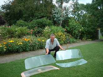 | ||||
Bill Coburn Moderator Username: bill_coburn Post Number: 558 Registered: 4-2003 |
Pat are you showing off that you garden as well??? I was not aware of casting new toughened windows Stephe. My experience here is very limited in fact the first I knew of the problem was the owner of an S series Bentley who used it for weddings. Seems that the new bride and groom had an almighty brawl in the back seat. The driver/owner stopped, the bride alighted and slammed the door very hard with of course the window half down. The resultant cracked glass was a sight to beheld. The owner was so crapped off he drove off and left the bride on the side of the road and he and the groom went to the local and got plastered! I replaced the glass with laminate as I couldn't get an original. | ||||
Stephe Boddice Experienced User Username: stephe_boddice Post Number: 26 Registered: 2-2005 |
Pat, The curved glass screens are most impressive - but not from the 20/25. The method of stabilising coachbuilt door and window frames is really dependent on what system was originally used. Some of the firms had very clever joint and junction systems whist other, lesser, outfits used long nails. As for the mounting of seatbelts - it really depends on how bad the crash is going to be. The bodywork is held to the chassis at only 8 or 10 points and it depends on the integrity of the surrounding frame and fasteners. If the belts are attached to the chassis, and the body moves in an accident, the belts will either be cut through or will act like cheese wires - take your pick. If the belts are attached to the bodywork, with reasonable anchorage strength, I would expect the belts to do their job in all but the worst of circumstances. How do you find time to cut the lawns as well? Bill, Nice story - I'm on the side of the groom and driver. I hope the argument was before the ceremony. When I rebuilt 3CP196 (PIII) it was necessary to replace all of the glass due to delamination and discolouration of the (?)perspex laminate layer. The 'experts' ('ex' meaning has-been and 'spurt' being a drip under pressure) said that they could not guarantee an accurate enough casting in toughened whereas there were confident with laminated even though this is a 4 step process. I asked why they could not just cut laminate to pattern from sheet and was told that I was a silly boy and should have been aware of the delamination risk. The upshot was that the pukka manufacturers took my original windows, cast new ones to pattern and returned the lot in a wooden crate filled with expanded foam. When I queried why 5 of the 8 pieces were larger than the original I was informed that the industry worked to a tolerance of +/- 4 mm (really helpful!). When shown that the pieces were 8 -10 mm out of whack they were a little embarrassed. Due to the timetable (and escalating cost) of the whole project it was decided that there was not enough time to remanufacture so they ended up grinding the 5 pieces to size. In other words, I have some pieces that are at risk of delaminating but at least I have the satisfaction of knowing that they were originally made properly - or something like that. Don't you just love working on old cars? The results are on www.boddice.co.uk/boddice10.htm | ||||
Patrick Lockyer. Grand Master Username: pat_lockyer Post Number: 497 Registered: 9-2004 |
Hi chaps its 06 so onward with the old girl. Dash in place with the most impressive walnut veneer with the 2005 finish the modern way with no cracking or distorsion.Pix 1 The ply finish round the column suround, should there be a sort of finisher or was the wood just painted black or dark brown.Pix 2. The 3rd pix is of the lower front screen with the glass and suround that will be allowed to flex but not break. The pix 4 is the roof taking shape. 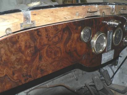 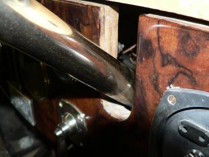 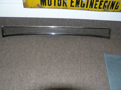 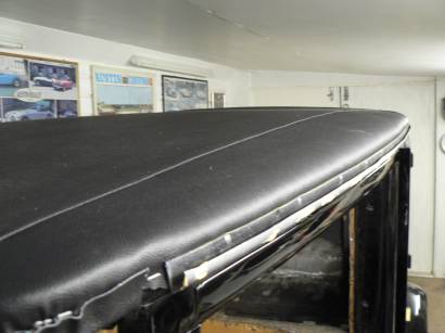 | ||||
Patrick Lockyer. Grand Master Username: pat_lockyer Post Number: 499 Registered: 9-2004 |
The front screens are in mounted in neoprene etc. now the fitment of door glass is progressing. Need some window winder handles before to long. Anyone with a pix of how they should look.  | ||||
Stephe Boddice Experienced User Username: stephe_boddice Post Number: 27 Registered: 2-2005 |
Pat, Window winders seem to have been at the discretion of the coachbuilder. Check Paul Beck's web site for a good selection. www.vintagesupplies.com Going back to the dashboard picture in the previous post: - what finish did you decide on? My suggestion would be to paint it dark brown or matt black. The whole dash layout is unusual for a 20/25; they usually retained the glass-fronted, 'squashed circle' set up with a wooden board in front. SB | ||||
Patrick Lockyer. Grand Master Username: pat_lockyer Post Number: 508 Registered: 9-2004 |
Thanks Stephe for the info,The winder shafts are threaded with a slot still working on a way of fixing more in time. Regarding the dash i think it had been got at before,all the column slots come down on this one they go up black paint is the order of the day. Pix no 1. Left hand cubby draw there are two looking good with the walnut,note the screw that was left in place as it whole thing would have to of been dismantled to get it out. Pix 2 just a little more of mahogany capping. Pix4 walnut panels in one coat two pack lacquire, flame curred. pix 3 cubby hole draw in place. Next the strange window question and the "time" trick with the door shuts. 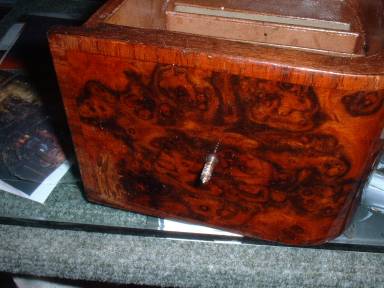  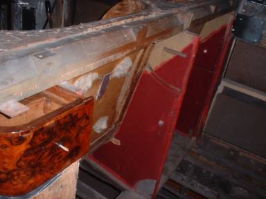 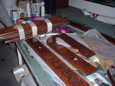 | ||||
Stephe Boddice Experienced User Username: stephe_boddice Post Number: 29 Registered: 2-2005 |
Pat, Wood looks like a nice finish. SB | ||||
Patrick Lockyer. Grand Master Username: pat_lockyer Post Number: 510 Registered: 9-2004 |
Hopeing this door tension trick will have cured the slight alignment probs. Will release and remove the the cable ties and hope that over the time they will stay put now. Have a mystery that i just can not work out,it is to do with the different position of the window lower sprocket rail[wood] on the n/s pass and the o/s drivers door,The n/s is higher than than the o/s. A great amount of time and trouble was taken in the makeing of the window mechanism that holds two pieces of glass?. Needless that it now is working ok with just a single one. Pix 1 and 2 are the n/s and o/s doors with the above to compare. 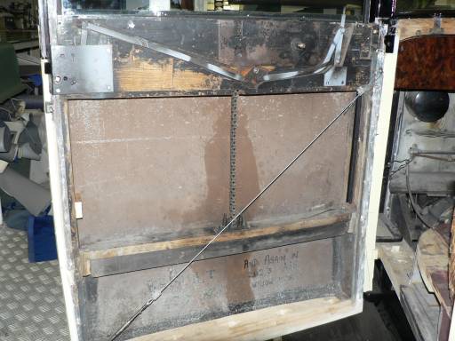  Pix 3 glass + 2 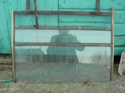 | ||||
Stephe Boddice Experienced User Username: stephe_boddice Post Number: 30 Registered: 2-2005 |
Pat, This old girl seems to be full of surprises. The sprocket rail positions do seem odd but do not really matter because the bottom stop-blocks are attached to the vertical styles. Were the 2-piece drop-glasses originally intended to have the lower segment hinged to allow hand signals without winding the window down? If so, presumably the nearside glass was just made to match. Just a thought (or two). SB | ||||
Patrick Lockyer. Grand Master Username: pat_lockyer Post Number: 514 Registered: 9-2004 |
stephe that is a good thought i will look to-morrow and see if there are signs of hinges. My thought was really a daft one like thinking glass was in short supply in the size needed because of all the work in making the frame to get over the prob.Cripes that dose not sound right. Been an exciting day i'm off to bed. Pix rear window fitted and setting. 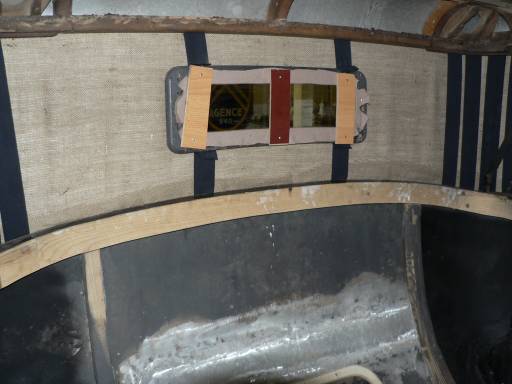 | ||||
Jonas TRACHSEL New User Username: jonas_trachsel Post Number: 5 Registered: 2-2005 |
Patrick Stephe may well be correct with his thought of the divided offside window being a device for giving hand signals. See the detail shots of my 20/25 hp with a similar arrangement either in www.RREC.co.uk -> registers -> 25hp -> Members' cars -> 1932 Mulliners Sports Saloon or in an abbreviated version in www.rrbew.co.uk -> Feature Articles -> (06/10/2005) 20/25 - GZU7 on the Road again. This arrangement was for turn signals by hand in the days before semaphores or flasher indicators. To the Moderators: This thread is getting quite long and takes its time to upload with all these pictures. Could the restoration history of Patrick's 20/25 hp be moved to a new/separate thread or re-started as a feature article? Jonas | ||||
Patrick Lockyer. Grand Master Username: pat_lockyer Post Number: 515 Registered: 9-2004 |
This is a picture showing the window surround trimmed with the headlinning material. This is removed and the headlinning is fitted and stappled, the finnisher is screwed over the top. Stephe Jonas and all. Yes i have had a look at the frame it is not original but am sure your explanation is correct. These cars did not have heaters and traficators so to open up the window to do hand signals on a cold day like to-day in the uk would be horrible. A flap of types would be far better. Regarding the handle shafts there comming off with square type made and fitted. 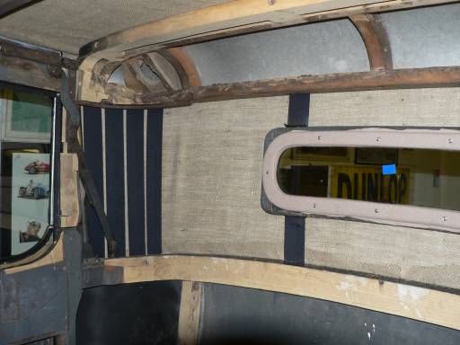 | ||||
David Gore Moderator Username: david_gore Post Number: 547 Registered: 4-2003 |
Hi Jonas, Yes, I am having the same problem with my dial-up connection. The problem is with the large number of pictures in the thread - Pat; please do not stop posting pictures because of this - this is a problem I do not mind having  Will see what I can do with my privileges otherwise I will have to have a talk with the Administrator to see how we can fix this problem. | ||||
Patrick Lockyer. Grand Master Username: pat_lockyer Post Number: 516 Registered: 9-2004 |
David. An idea may be of use if it could be carried out is to put all this in folder say part 1 then have a link to it somehow, just a thought. Then i carry on till the next thread becomes long then part 2.and so on? In the meantime i will carry on if it is not to tireing. | ||||
RR Forums Administrator Board Administrator Username: admin Post Number: 53 Registered: 10-2002 |
This is a possible solution: use "attach" rather than "image" when you want to post images. It's not as pretty but you get to choose which images you want to see. [After posting we find that Discus won't show an image as an attachment. Back to the drawing board...] 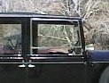 The lower part of this window (on Hooper-bodied 1930 Phantom II 147GN) can be dropped with a flick of the wrist so you can stick your arm out and signal, or pay tolls, or maybe occasionally even "flip someone off". (Message edited by admin on January 26, 2006) | ||||
Richard Treacy Grand Master Username: richard_treacy Post Number: 953 Registered: 4-2003 |
You can always save the file as a PDF (*.pdf) or WORD (*.doc) file etc, and upload it using <Upload Attachment> to give the user the option to view it or not. Like this:
| ||||
Patrick Lockyer. Grand Master Username: pat_lockyer Post Number: 517 Registered: 9-2004 |
Richard, i can use paint shop pro but when i tried to do as you have done with an illustration a while ago of valve springs following the straight line law all i ended up with was a paper clip. | ||||
David Gore Moderator Username: david_gore Post Number: 548 Registered: 4-2003 |
Hi Richard, Your suggestions are valid for those of us who have access to Adobe Acrobat or image processing software and use them often enough to be able to quickly modify the images for posting. In the case of Word; you can modify the images in a document after insertion by right-clicking the image, selecting "Format Picture" from the menu then selecting the "Size" window and entering smaller values for the height and width dimensions or reducing the % values in the SCALE section before saving the document. The risk we run is that inexperienced or novice users will post images that are too small to be of any use and they cannot be enlarged without becoming pixellated.. Got to keep searching for a simple easy-to-use solution. | ||||
Richard Treacy Grand Master Username: richard_treacy Post Number: 955 Registered: 4-2003 |
I have opened a new thread on posting files under General Discussion. |