| Author | Message | ||
Brian Vogel Grand Master Username: guyslp Post Number: 1208 Registered: 6-2009 |
Hello All, I am considering installing a replacement distributor into SRH33576 and keeping her existing distributor as a potential spare for LRK37110. The instructions prior to removing the distributor are here: 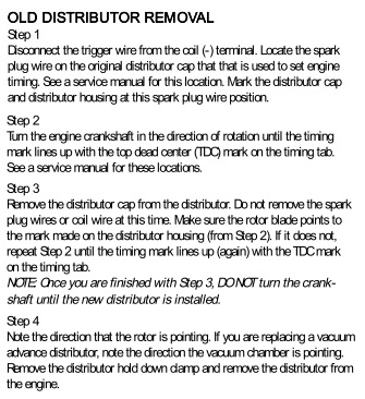 What I'd like to know from those who've "been there, done that, got the T-shirt" is just how difficult the seemingly easy step #2 really is. These instructions are conceptually and theoretically simple to follow. However, I long ago learned the truth of the statement: In theory there is no difference between theory and practice; in practice, there is. Also, techniques for actually turning the engine to achieve the noted TDC positioning for the A1 cylinder would give me an idea whether this is something I'd even consider undertaking. Brian | ||
David Gore Moderator Username: david_gore Post Number: 1533 Registered: 4-2003 |
Brian, Been there, done that. The undocumented essential procedure to facilitate Step 2 is to remove all spark plugs before turning the engine by hand. Much easier to rotate the crankshaft with no compression than with compression. I was able to use the fan belts to rotate the crankshaft after removing the spark plugs however I forget if it was possible to get a socket onto the crankshaft pulley if needed [a little voice keeps telling me a special socket is required]. If, by chance, the crankshaft is inadvertently rotated whilst there is no distributor in place; I recall Bill Coburn documenting, in Tee One Topics, a technique for ensuring cylinder A1 is Top Dead Centre on the compression stroke for correct timing of the distributor using the timing marks for a successful engine restart. Nail polish is a very useful alternative to a felt pen for marking the distributor body and cap. | ||
Geoff Wootton Grand Master Username: dounraey Post Number: 639 Registered: 5-2012 |
The instructions give you a 50/50 chance of the engine starting. Why? - because they omit to mention TDC must be set on the compression stroke. This is why setting TDC is such a hassle; you have to remove the rocker cover and monitor the A1 valves to make sure they are both closed at TDC. The other possibility is the inlet valve is closed and the exhaust valve is open (exhaust stroke). Personally I would not bother to find TDC. I would remove the old distributor and take measurements against the new one. As long as the slot at the bottom of the distributor is at the same angle with reference to the rotor arm and as long as the lugs that attach the distributor cap are in the same place it is just a case of switching them. If these measurements are not the same, then I'd use the instructions given above to set the timing up from scratch. Geoff | ||
Brian Vogel Grand Master Username: guyslp Post Number: 1211 Registered: 6-2009 |
Geoff, Well, I have myself in the 50/50 chance for LRK37110 right now, as I realize that I forgot to take a picture of which way the rotor arm was pointing on her when I removed the distributor from her. When I put it back on the are will either be correct or off by 180 degrees. I had not had the insight that you offer in your final paragraph. But why does the location of the lugs that attach the distributor cap matter? It would seem that those could be at any random spot opposite each other and between two leads, depending on the manufacturers whim. Unless, of course, you're talking about the clamp on the distributor base that holds it in place on the car and that you loosen the bit that clamps to the distributor to allow it to be turned for timing purposes. I'm just trying to wrap my head around this at the moment. David, if you've ever seen many of the pictures I've put up over time you already know that I'm a huge fan of color coding and the use of nail enamel, particularly when dealing with a slew of electrical connections. Marking things that mate or should line up with nail enamel is already one of "my things." Brian | ||
Geoff Wootton Grand Master Username: dounraey Post Number: 642 Registered: 5-2012 |
Hi Brian The lugs that attach the distributor cap matter as they define the position of the HT leads relative to the rotor arm. If the lugs/clips are in a different position on the new distributor, then all the HT leads need to be removed and correctly repositioned. If I was in this situation, I would revert back to finding TDC on the compression stroke and re-connecting them so that the A1 lead was positioned nearest to the rotor arm and then follow the firing order for the other leads. It would of course be possible to measure the offset between the original and new distributor and reposition the HT leads accordingly, but things can easily get confused when you are deviating that far from standard procedure. BTW - I purchased a set of clip on numbers for HT leads from Pep Boys for $4.25. They run from 1 - 8 and are very useful for times when the HT leads have to be pulled from the distributor cap. Geoff | ||
Geoff Wootton Grand Master Username: dounraey Post Number: 643 Registered: 5-2012 |
Hi Brian It occurs to me we may be at cross purposes here. When I stated my method of not using TDC I was assuming the original distributor cap was being used and the HT leads had not been removed. Geoff | ||
Brian Vogel Grand Master Username: guyslp Post Number: 1213 Registered: 6-2009 |
Geoff, It appears we are "talking past each other" in this case. I am considering replacing the original Lucas distributor entirely and keeping it as a spare for LRK37110. SRH33576 was so far from original when I got her (which happens when you have a RHD to LHD conversion, for starters) that originality is not even a consideration. She's also already got the Range Rover distributor cap and a replacement rotor arm. I do know that I need to keep the leads connected to the distributor cap in correct firing order. There are stickers on most of the HT leads already (one or two may be missing) giving their respective A-bank and B-bank numbers. Someone also wrote the same information on the distributor as well. I've had occasions where I've taken off a lead or two to get at things near the firewall, like the ballast resistor, for instance. It's very handy to have those markings to double check against. Brian | ||
Bob UK Unregistered guest Posted From: 94.197.120.203 |
The easy way. at the bottom of bell housing is a cover which has tdc shown. Lever fly wheel with prybar to turn. At Tdc Mark rotor position on dizzy body, Bosch already have a line. Centre punch works. Just fit new dizzy in same rotor position and then Mark. Incidently these dizzys are long lasting and the advance device angles are not crucial. As long as full advance is available then the curve between is guess Work. So if the advance is showing smooth on a strob up to full advance then that bit is ok. Mark the pulley in quarters then check each cylinder timing my dizzy has about 2 degrees. How to overhaul. Fit new springs. Check the shaft for radial play. None allowed when oiled. The cam should move on the shaft a with no sideways oil again. Check gap on each cam. Any high ones, stone the cam. Timing scatter can be cured by stoning the lead up to the cam. But requires the dizzy to be running. A lathe or drill works. Use strobe but remember the dizzy is half speed. So 45deg. If the dizzy is slightly worn then electronic will help accuracy. The ring gear will not be damaged by levering to turn. Dizzy are easy diy. I seldom see worn everything and most times only springs and points are needed. Plus oil. Long lasting. A1 should be rotor pointing to front and a bit to a bank. I cannot emphasis oil it enough both electronic and points the electric are oil proof. so a smear of oil is flicking on the sensor is ok. Points work fine when oily some suggest that oil suppresses the spark for a cleaner break. so all easy stuff to make life easy and cheaper. Note a lot of small mechanism appear to work freely without oil. But when working due to loads won't be as free. So oil is marvelous stuff. Rod brakes are like that. (Message approved by david_gore) |