| Author | Message | ||
Randy Roberson Frequent User Username: wascator Post Number: 79 Registered: 5-2009 |
Hello, on SRH9391, a 1970 Silver Shadow, after an accumulator-control valve overhaul, the left brake warning lamp will not illuminate, even with the lamp test switch activated. The bulb is good as proven by swapping the bulbs left-right. I do not have the rear pump going yet, I hope it is air locked: the right lamp is lit due to no pressure in the rear accumulator. The front accumulator is pressuring up. Nevertheless, I uncovered the relay on the right side of the firewall: it has four spade connectors. I opened the fuse panel and did not find any fuses out of order. If anyone has any experience or advice about finding the problem here, I need assistance. | ||
Brian Vogel Prolific User Username: guyslp Post Number: 174 Registered: 6-2009 |
Randy, I'm not quite sure what you're referring to by the "lamp test switch." Have you done the brake pump test to see if the thing will illuminate if the system is intentionally depressurized? I'm just wondering if it can be made to illuminate in that condition or when an attempt is made to start the car (that's presuming the original SY series does the "light all the warning lamps" bit when you crank the car to start it). If it doesn't light under any circumstance I'd presume you have a wiring problem "in front of" the place where any of the things that could send power to the light come together in the circuit. Nothing definitive, just thinking aloud. Brian | ||
Geoff Wootton Experienced User Username: dounraey Post Number: 46 Registered: 5-2012 |
Randy - I had the same thought as Brian - have you depressurised the system. A freshly reconditioned accumulator can take well over 100 presses of the brake pedal before the warning light illumunates. I counted 128 on the front circuit on my car. Just a thought. Geoff. | ||
Randy Roberson Frequent User Username: wascator Post Number: 80 Registered: 5-2009 |
New information: on a Silver Shadow I, there is a button on the dash, just above the steering column, which, when pressed with the ignition switch on, will illuminate all the dash warning lamps, as a bulb test. This evening I turned the switch on, pressed the button, and none of the lamps which were not already lit, came on. Aha! It is not just the brake warning lamp. I pushed it about three more times, then the bulbs all came on, including the brake warning lamp in question. I can hear clicking under the bonnet when the lamps come on, so I conclude this is a relay acting, and perhaps it is either sticking, or the switch is a little dirty, or? Anyway, the lamp illuminated, which I take as progress. Also I reread the Owner's Handbook: the right warning lamp is for the front pump/system and the left is for the rear. Since the front accumulator has pressure and will operate the brakes normally, I am having to redigest what is going on here. I plan to place a vacuum on the rear accumulator bleed screw via the Mity-Vac and see if I can get the vital juices flowing in the rear system. More later (the fun never stops...). | ||
Richard Treacy Grand Master Username: richard_treacy Post Number: 2729 Registered: 4-2003 |
My goodness. When all else fails read the driver�s handbook. That button dates back to 1952 or much earlier in its several incarnations,. It started as an oil level test, expanded to include other functions, then went back to just the oil level for the SY2 cars onwards in 1977. Even my Conti R has one, as do my T-Series, R-Type and Turbo R. On your car it should at least: � Convert the fuel gauge to an oil level gauge � Sound the coolant overtemperature buzzer � Illuminate the brake and low coolant warning lamps If any of those tests do not respond then urgent attention is required. On SY2 cars, the warning lamps are illuminated for test purposes whenever the starter is cranked. RT. | ||
Hubert Kelly Frequent User Username: h_kelly Post Number: 67 Registered: 3-2012 |
Hi Randy, this might be of no use to you but I did find it helpful in diagnosing a similar problem. If you get a piece of wire, connected to it 12 volt + and a lamp/tester(12 volt) brush the lamp side or buzzer side against the accumulator valve low pressure device on the accumulator(ie where the wire spade normally connects to low pressure device) when the accumulator is depressurized it acts as a negative earth thus lightening the lamp, if it don't light the accumulator may be charged enough so as to brake the negative earth(depressurize if you wish to confirm test diagnosis is actually working correctly) THIS WONT FIX THE PROBLEM BUT MAY AID DIAGNOSIS? HK | ||
Martin Taylor Unregistered guest Posted From: 222.153.223.109 |
The warning lights are fed from the ign circuit +12v, to test the lamp ground the wire going to the pressure switch with a clip lead or similar, the switches stick often and sometimes need a little bit of file work to make all the parts move. When you press the test button a relay is activated to put a ground on the negative side of the lamps and , buzzer and to connect a resistor across the input of the low coolant relay, the relay may not pull in if your battery voltage is low, connect a charger to the car while testing as the ign and levelling solenoids will flatten a battery in a very short time and give misleading results. Incidentally on my car at least the brake light failure bulb does not operate with the test switch. (Message approved by david_gore) | ||
Jan Forrest Grand Master Username: got_one Post Number: 430 Registered: 1-2008 |
As I recall it there's an article regarding the accumulator pressure switches somewhere in the Tee-One Topics. It describes how these switches can fail - usually through contamination caused by a slight weepage of hydraulic fluid - and how to dismantle/overhaul/clean them. As I remember it the system(s) need to be depressurised first so that the switch can be removed and the hole then plugged with a bolt to prevent the loss of too much fluid. I've been meaning to have a look at both the switches on SRH24518 for some time now, but have delayed doing it until I have the correct size and format for the switch's thread so I have the right bolt to hand first. Anyone? | ||
Paul Yorke Grand Master Username: paul_yorke Post Number: 931 Registered: 6-2006 |
No real need to blank off the hole once depressurized . Once apart you will find the contact is operated by a resin plunger about 6mm long. This plunger seizes in the brass body and gives either a lazy action or can seize in the on or the off position. false readings. file off the edge so it can move freely through the brass piece . New rubber diaphragms are available but rarely needed . | ||
Geoff Wootton Frequent User Username: dounraey Post Number: 59 Registered: 5-2012 |
Here's my understanding of the accumulator pressure switch. The actual switching is carried out by a membrane switch located inside the hydraulic connector side of the valve body. It is pictured second right in the photo below. 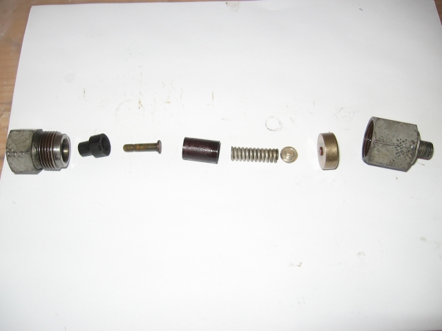 The part on the far left of the photo is the valve body that houses the electrical connector. left -1 : fibre bush to insulate electrical connector from valve body. Left -2 : Electrical connector. Left -3 : Fibre bush to insulate spring from valve body. Left -4 : spring Left -5 : spring / membrane switch connector Left -6 : membrane switch Left -7 : hydraulic connector end of the valve body. When all these parts are assembled the membrane switch is held between the two halves of the valve body. The other side of the membrane switch, not visble in this photo forms a seal with the valve body. This seal is maintained in place by pressure from the spring. The switch when unpressurised is in the off position. When pressurised the contacts within the membrane switch close and a connection to ground through the valve body is made. Essentially, there are no moving parts other than the diaphragm of the membrane switch. Never try to "free" a non-working switch by pushing a pointed tool into the valve body. If you pierce the diaphragm hydraulic fluid will be forced in to the body of the switch when it has been reconnected and the engine started. If you are disassembling the valve and the membrane switch has seized in the housing free it with releasing fluid and tapping the valve body lightly on a wooden surface. There is a photo of the disassembled membrane switch switch in tee-one topics Number 9, page 93. | ||
Geoff Wootton Frequent User Username: dounraey Post Number: 60 Registered: 5-2012 |
Correction to above post - membrane switch is normally on. When pressurised switch is turned off - sorry for the error. | ||
Paul Yorke Grand Master Username: paul_yorke Post Number: 932 Registered: 6-2006 |
Geoff, you've missed 3 parts out. Left 5 is actually the switch contact (silver) left 6 (Brass coloured) is actually made up of 3 parts. Brass body rubber membrane Resin / fibre plunger The silver switch contact is pressed towards the brass part by spring pressure. It presses the resin plunger towards the accumulator and deflects the rubber and closes the electrical circuit. As accumulator pressure increases the fluid pushes against the rubber and pushes the plunger to the left and disconnects the silver contact from the brass and put the warning light out. 1mm or less movement. If the plunger can not move freely, the light will not operate correctly. It will often need tapping out with a small hammer and drift because it has become seized solid. Once apart, you can ease the plunger by either filing it or enlarging the hole in the brass part. I always file or sand the plunger. | ||
Nigel Johnson Prolific User Username: nigel_johnson Post Number: 106 Registered: 12-2008 |
The resin plunger is referred to as a Venusian sloths nail paring. Mainly because of its price! Bill Coburn named it, so it must be true. Regards, Nigel. | ||
Paul Yorke Grand Master Username: paul_yorke Post Number: 933 Registered: 6-2006 |
I have often wondered what the hell it is made out off! lol. I defer to Bill's superior knowledge and years of worldly experience on this one! | ||
Bill Coburn Moderator Username: bill_coburn Post Number: 1472 Registered: 4-2003 |
I wish you two hadn't brought up this matter as I am still trying to square off with the Society of Megalonychidae who look very carefully at the welfare of this protected species. Concomitant with this is an arrangement I am making with a well placed manicurist who looks after a fair population of Megalonychidae including their toenails. I am hopeful if this comes off we will have an alternative supply of plungers!! | ||
Jan Forrest Grand Master Username: got_one Post Number: 431 Registered: 1-2008 |
If I recall correctly the horn of a unicorn has been put forward as an acceptable substitute for the sloth nail paring. The only trouble in harvesting such is the need to first find a beautiful 30+ year old virgin to charm it while you saw the horn off. Unicorns are plentiful by comparison! In the meantime I shall be very careful when dismantling the switches. Unfortunately that will have to wait until the current temperatures start to climb back into the positive half of the spectrum. With 2 of the 3 major arteries between the North West and the North East of the UK currently impassable through heavy snowfalls Lancashire is almost cut off from the rest of civilization. |