| Author | Message | ||
Chris Miller Experienced User Username: cjm51213 Post Number: 42 Registered: 5-2013 |
Hi Folks, The Accumulator sphere Nitrogen injection valves are rebuilt. I can only produce 125 PSI with my shop compressor, which is a pretty low threshold compared to 1,000 PSI, but it is non-zero, free, and allows me to prove that the accumulator is functionally holding pressure. I could fully charge them with Nitrogen now and watch them over a few days to be sure they hold pressure, before I re-install them, and that is probably a good idea. This is the easy part. The "Charging Valves" are sitting on my bench and I'm thinking (and hoping) that I don't need to rebuild them. They seemed to be working correctly; of the four components -- two valves and two spheres, one sphere was known defective, but probably the valve was functioning, since the red "underpressure" warning light for that system only occasionally engaged. Which also raises the question of the integrity of the pressure switches and how I test them? Does a malfunctioning switch look like: 1) "zero pressure", meaning the light is on until the switch turns it off, which won't happen? 2) "adaquate pressure" meaning the light is off until the switch turns it on, which won't happen? If I were designing this, I'd chose option 1, but I didn't design this, so my sensibilities don't really enter into it. In any case, removing and re-installing these is not a big deal, so I can test them in situ, and I think I know this procedure: Start the engine, and watch the lights go out, indicating "All Well" and then turn the engine off and drain the pressure by pumping the brake and watch the lights come on, indicating, "Low Pressure". Comments? So, the question for discussion: Do I need to rebuild the charging valves just because I can? Is there any known bench testing procedure? Deferring now and rebuilding them next year would be a monumental failure in judgment, because they are really difficult to remove and re-install. However, rebuilding them now when it is completely unnecessary violates "If it ain't broke, don't fix it.", which is very good advice indeed. How often has anybody seen the charging valves fail and what does a failure look like? ================= Later that day... In light of the questions I asked, I went looking for hydrostatic test equipment which lead me a merry chase but ultimately I arrived at: http://www.enerpac.com/en-us/industrial-tools-imperial/hydraulic-pumps-and-valves/hydraulic-manual-pumps/p-series-hydraulic-low-pressure-hand-pumps These pumps expect a "jack" at the other end, but I can put brake components where the "jack" would be. I can use brake fluid in the pump reservoir, but it will degrade the BUNA-N and polyurethane seals in the pump, which is rebuildable, but even better... I can use castor oil, which 1) does not contaminate the RR hydraulic system components and 2) does not degrade the pump and 3) is something I need in the home-brew RR363. Now, I have a way to bench test my hydraulic system components, which will probably answer some of the questions I posed earlier. Thanks for the help, Chris. | ||
Brian Vogel Grand Master Username: guyslp Post Number: 789 Registered: 6-2009 |
Chris, The pressure switches use what you call "option 1." The warning lights remain on until adequate pressure is formed causing a circuit to be closed to turn them off. I hate to say this, but will, you really need to use the "search" feature and read up on this whole process. Every one of the questions you're asking has been covered in great detail before, and it truly seems that it's great detail that you're after. It's here and once you've reviewed existing materials you can frame either new questions or get very specific additional information by asking. If you're questioning whether you should remove the tiny circlip and spring that hold the metal ball bearing seal in place and then polish the seat on the accumulator and replace (ideally) that ball bearing the answer is yes. You do not need a new spring or circlip. If the ball bearing is "looking perfect" you could just polish it, but a new one is a better idea (stainless if you can get it). While it may be tedious to get that micro-circlip out, it's not difficult. Since this sealing method on the charge port is well known to be "less than perfect" you really want to take the time to make it as "perfect as can be" if you've got an accumulator apart for rebuilding. Brian | ||
Chris Miller Experienced User Username: cjm51213 Post Number: 44 Registered: 5-2013 |
Hi Brian, Thanks for the advice. About "searching"... Yeah,... Questions get asked; Questions get answered; Questions get asked again... Annoying! And I am guilty. In my defense: 1) Everybody learns; techniques improve; resources vary. The recorded answer may not be the current best answer. 2) Often the solution to a problem is asking the right question, and this is my ponderous way to plan my attack -- I write about it and zero in on the right questions. I don't always know the right question up front. The essay helps frame the issues and filter extraneous and irrelevant aspects. 3) This is a club and a club is about community and membership. It is also a reference library, but mostly it is a club and I like having a discussion; a discussion brings up things I hadn't considered, and makes me feel like I have friends. You've been helpful, so I don't want to annoy you. Actually, I don't want to annoy anybody, so if my participation annoys you, then I am truly sorry, but self-censorship taken to the extreme means nobody participates, and where do I draw the line? The truth is, I like it better when I chatter along and other guys chip in. You are free to ignore me, but I hope you don't. Chris. | ||
Jim Walters Experienced User Username: jim_walters Post Number: 11 Registered: 1-2014 |
Chris, while you have the accumulator valves off rebuild them. They very well could be full of debris and not functioning correctly, or the interior walls could be corroded allowing pressure to bypass the O ring seals. They are not difficult to do, but make sure you note the shims under the valve spring and put them back in the same place. Ideally, you need a test rig such as the one I built to set them to the correct relief pressures, but if you put the same shims back where they were you should be close. I built my test rig using a bottle jack. I removed the ram, and replaced the O rings with EPDM ones. It is filled with RR363. 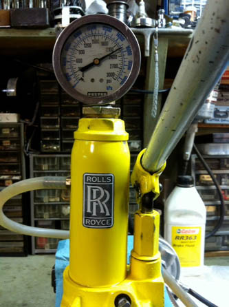 SRE22493 NAC-05370 www.bristolmotors.com | ||
Jim Walters Experienced User Username: jim_walters Post Number: 12 Registered: 1-2014 |
You asked what a failed valve looks like? Well maybe not failed, but I pretty well guarantee you the inside will look like this, or worse. 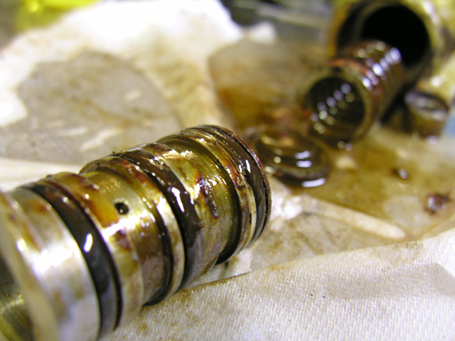 And here is what the internal parts look like cleaned up. You can usually get away with just replacing the 3 large O rings and the one smaller one on the end plug. See Brian's O ring list for the specs. 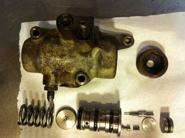 SRE22493 NAC-05370 www.bristolmotors.com | ||
Chris Miller Experienced User Username: cjm51213 Post Number: 45 Registered: 5-2013 |
Hi Jim, Brilliant! I suspected that I could make such a test rig from a bottle jack, but I didn't know how much pressure a bottle jack pump could create, so I bought a legit pump that produces 10,000 PSI and is used for small and light hydraulic applications for $175. I just got back with it and I *was* felling very proud of myself for being so economical... I plan to fill mine with castor oil. And now that I have the test rig, I will know if I have improved or degraded the condition. I didn't like "flying blind"... I halfheartedly tried to remove the cap by inserting an appropriately sized nut in the hex indentation and using a standard wrench, but it is resisting me. Any last words of advice? Thanks for the help, Chris. | ||
Geoff Wootton Grand Master Username: dounraey Post Number: 391 Registered: 5-2012 |
Hi Chris The plug will be very tight. Just persevere with release oil and plenty of careful force and it will come out. I also recommend that you replace all the O-rings. As Jim said, check out Brian's list for the correct spec. You can buy most sizes EPDM O-rings from Graingers and I believe there are some outlets in Sacremento, so no need to wait for them mail-order. Geoff | ||
Brian Vogel Grand Master Username: guyslp Post Number: 790 Registered: 6-2009 |
I have to say I'm getting confused by "changing flying terminology." I presumed that "charging valves" meant the charge port valves, not the accumulator control valves. I just sent Benoit Leus annotated photos of the accumulator control valve exploded. As Jim notes, you generally only have to worry about replacing the O-rings. If anyone else wants these photos just send me a private message with your e-mail address. Brian | ||
Brian Vogel Grand Master Username: guyslp Post Number: 792 Registered: 6-2009 |
Scratch that last line about sending me a private message. I decided to further update the annotated photo to include absolutely every piece shown and then to post it here, along with additional detail photos, in a thread entitled: Accumulator Control Valve (ACV) - Exploded View Photos. They're now officially a part of the online historical record. Brian | ||
Brian Vogel Grand Master Username: guyslp Post Number: 793 Registered: 6-2009 |
Geoff Wootton wrote: The plug will be very tight. Just persevere with release oil and plenty of careful force and it will come out. It also doesn't hurt to have a long breaker bar, a 1" socket, and that piece of 1" hex bar stock to persuade that end plug to break loose. With the ACV body in the vice this setup worked like a charm for me every time. Of course, when reassembling the ACV a dab of anti-seize lubricant on the threads of the end plug, adapter, and other threaded bits not in contact with RR363 is de rigueur. Brian | ||
Chris Miller Experienced User Username: cjm51213 Post Number: 46 Registered: 5-2013 |
Hi Folks, I've succeeded opening the Accumulator Control/Charging valve. I didn't know *what* it was called, but when I googled "Charging Rolls Royce Hydraulic Accumulator", I got pictures labeled "Charging Valve",so I assumed... Brian, your pictures are *really* good. Very helpful. I don't see where the "Non-return" valve component should be. It looks like it should be interior to the bobbin, but I see nothing. Any hints? Thanks for the help, Chris. | ||
Brian Vogel Grand Master Username: guyslp Post Number: 794 Registered: 6-2009 |
Chris, The piston & sealing ring fits into one bore in the end of the bobbin that faces the sealing disc and the non-return valve and spring fits into another bore on the same side. This is instantly obvious once you have the end plug, sealing plug, and the sealing disc out. You just thread a bolt into the end of the sealing plug that faces out and pull it straight out with pliers then tap the ACV body to make the sealing disc fall out. Brian | ||
Richard Treacy Grand Master Username: richard_treacy Post Number: 3018 Registered: 4-2003 |
Whilst the o-rings quoted are close, the small one for the bobbin is not a standard BS size. Unfortunately, some enterprising spares outlets and workshops have followed the guide and have been selling kits with the wrong bobbin 0-ring and they leak after a few months. It may save a dollar or two short-term but cause heartache later but also the proper kits include the tiny teflon sleeve for the valve beneath the bobbin. Best buy the rebuild kits from reputable spares outlets. Also, the pressure switches vary. Some have contacts that open at about 100 psi (ie as soon as the brake pump has done a few cycles and the pressure jumps immediately to 1,000psi before rising slowly to above 2,000psi), whilst others need about 1,200 psi (that can take a minute or longer). If the latter goes out immediately it is usually an indication of a spent sphere. In general they are like oil pressure warning lamps on the motor - they go out to show that something is going on but not much more. RT. | ||
Chris Miller Experienced User Username: cjm51213 Post Number: 48 Registered: 5-2013 |
Hi Brian, Yeah... I found it with your help. The sealing disk was stuck in the cavity and I wasn't aware the I was seeing a removable component. After reading your post, I realized that there had to me more because there was no reason to have a plug in a blind cavity. Thanks for the help, Chris. | ||
Chris Miller Experienced User Username: cjm51213 Post Number: 49 Registered: 5-2013 |
Hi Jim, > Chris, while you have the accumulator valves off rebuild them. Really good call... The seals were pretty degraded and most broke while removing them from the bobbin. Thanks for the help, Chris. | ||
Brian Vogel Grand Master Username: guyslp Post Number: 795 Registered: 6-2009 |
Richard, Unless Crewe Original is one of those "enterprising spares outlets" I can assure you that the three O-rings supplied for the bobbin are all precisely the same size. I've measured several of these official kits at this point. The O-rings that fit the bobbin are not differentiated from one another at all in size and are AS568A-212 standard EPDM O-rings. Why in heavens name would the kits include three o-rings of a single size, loose, and nothing denoting that an "odd one" that has a specific placement is included? I'll stand behind my list. The three ACVs I've rebuilt using the specified sizes that have remained fully functioning for time periods well beyond "a few months," as have many others who've rebuilt using those sizes. You can't argue with success, and long-term success. Brian | ||
Chris Miller Experienced User Username: cjm51213 Post Number: 50 Registered: 5-2013 |
Hi Richard, My rebuild kit has the Teflon sleeve, but I can't see how to disassemble that needle to replace it. Any advice? Thanks for the help, Chris. | ||
Brian Vogel Grand Master Username: guyslp Post Number: 796 Registered: 6-2009 |
Chris, Try as I might I have been unable to locate the picture that I know is "somewhere, out there" on the internet of the homemade version of the "official tool" used to get that tiny square ring placed in the piston channel and then the fluon ring on top of it. If memory serves, it looks rather like a small, pointed ice cream cone, with a hole drilled in the middle to allow it to slide on the pin at the end of the piston. It has a slight countersink near the top, too, to allow the shoulder next to the pin to slide in so you have a continuous surface. You lube it, and the ring in question, up with RR363 and then begin the tedious process of slowly wiggling and stretching the ring up the cone, on to the piston, and then allowing it to snap into the channel when you get there. If someone else knows where this information exists in pictorial form please add that information here. Brian P.S. to Richard: The small O-ring that goes in the interior of the bobbin is an AS568A-113. You are the one who once observed that engineering is done to match standardized seal sizes available and not the other way around. | ||
Geoff Wootton Grand Master Username: dounraey Post Number: 392 Registered: 5-2012 |
Chris Could I implore you to measure the O-Rings in your rebuild kit. From Brian's document there should be: ID OD CS 3 AS568A-212 7/8" 1-1/8" 1/8" 1 AS568A-113 9/16" 3/4" 3/32" 1 AS568A-218 1-1/4" 1-1/2" 1/8" Now here's the rub: The sizes stated are fractional nominal and you need to check the AS568 tables to get the precise dimensions: CS ID AS568A-212 = 0.139" 0.859" AS568A-113 = 0.103" 0.549" AS568A-218 = 0.139" 1.234" I really strongly recommend that you take a few seconds to measure the rings in your kit. I reconditioned my ACV's and Spheres using rebuild kits from a highly reputable company and found the O-rings to be variously around 20 thou under-sized. The resultant leaks that appeared after a few weeks use required me to remove and re-rebuild my accumulators. I can absolutely confirm that the specs Brian quotes are correct. Geoff | ||
Chris Miller Frequent User Username: cjm51213 Post Number: 51 Registered: 5-2013 |
Hi Geoff, On the strength of your recommendation, I will do so. I should have thought about this last night before I put the O-rings on the bobbin, but I think I can still accurately measure CS with them in place. They are very slightly loose in position, meaning the bobbin is exerting zero deforming force on them. From the position of rank amateur inexperience, they *looked* like they fit and I was able to insert the bobbin with a bit of resistance that seemed appropriate give its function. But, what do I know? I'm not exactly sure how accurate my measurements will be because I don't know exactly how much variability I will see; the material is pliable and will be subject to different measurements depending on how sensitive the measurer (me) is to the material deformation. What are the tolerances of these dimensions? Which dimension is typically found out of spec? CS (ring gauge?), ID or both? I got my kits from Albers in Zionville, but I have no experience with any of this, and they were "aftermarket" kits, meaning Albers themselves may have assembled them. Thanks for the help, Chris. | ||
Brian Vogel Grand Master Username: guyslp Post Number: 797 Registered: 6-2009 |
Chris, There are untold thousands of AS568A size charts out there. Here's a webpage with one I like that shows not only the individual ring sizes, but how the "hundred classes" vary in inner diameter. The really good charts also include the "slop factor" (correctly known as tolerance) for each measure: ID, OD, CS. Unless you have a company that's willing to lie, anyone claiming that they conform to the spec has to have the specified measurements within the tolerance for each. Seals are somewhat precise, but there is a "within normal limits" (WNL) range for any specific size. Brian, who figures if you got them from Albers it's a virtual certainty that they'll be OK, but "measure twice" never hurts anything. | ||
Chris Miller Frequent User Username: cjm51213 Post Number: 52 Registered: 5-2013 |
It is *so* much easier to avoid problems, than fix problems... Chris. | ||
Geoff Wootton Grand Master Username: dounraey Post Number: 394 Registered: 5-2012 |
Chris I did not buy my kits from Albers so I agree with Brian that it's virtually certain yours will be ok. If you can measure the cross sectional diameter that would clinch it. The 3 AS568-212 rings are listed as CS diameter of 1/8". The spec is 0.139" rather than the logical 0.125". So, if your measurement is closer to 0.139 than 0.125 then they are ok. (I understand the problem of getting access with the rings in situ). I worked to a tolerance of 5 thou when checking out my second, correct sized rings. Geoff | ||
Jim Walters Experienced User Username: jim_walters Post Number: 13 Registered: 1-2014 |
Here is my tool for installing the Fluon ring on the piston. The larger end is bored and countersunk so it sits flush on the piston. It is very important to heat the ring in warm brake fluid so it will stretch to slide over the tool onto the piston. 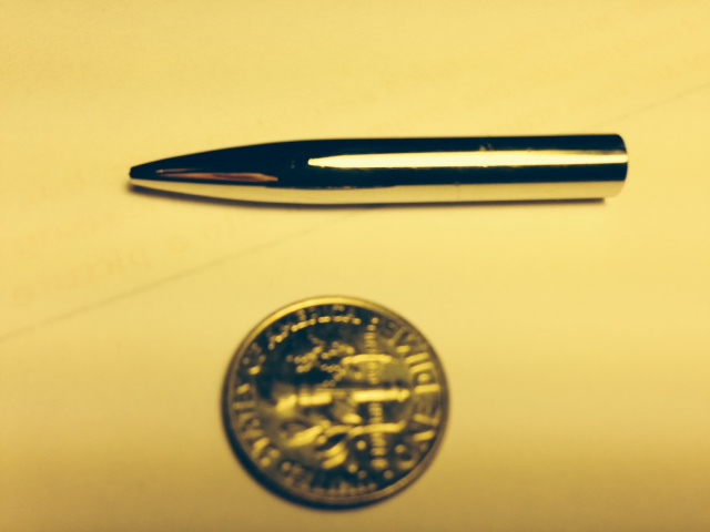 SRE22493 NAC-05370 www.bristolmotors.com | ||
Chris Miller Frequent User Username: cjm51213 Post Number: 87 Registered: 5-2013 |
Hi Folks, So, I have developed the facility to perform hydraulic bench testing on my re-built accumulator and I wanted to share the experience with you, because apparently I am a moron... The manufacturer recommends that the pump not be subjected to brake fluid for all the normal seal preservation reasons, but Castor Oil is not going to club any seals. Turns out the pump I bought has exactly ONE o-ring which can be replaced in about five minutes, so this is not a big deal in any case. However, I had decided to go with straight Castor Oil. Castor Oil is a lot more viscous than the OSI AW 32 standard. It was this knowledge that helped me mis-diagnose my problem; I misinterpreted non-linear behavior as a failure, and I was willing to blame Castor Oil for a pump failure. Phase One: Open the bleed valve and watch fluid circulate from the pump, through the ACV, out the bleed valve, back to the reservoir. Watch for the bubbles to dissipate. So far, so good. Phase Two: Develop enough pressure for the ACV to bypass the accumulator. This was where my "failure" occurred, and I should have realized what this phase would look like -- quickly reach charge pressure since there will be no volume changes, and then a leisurely trip to cut-out pressure as fluid accumulates and fluid re-circulates to the reservoir. That didn't happen. I got to 700 PSI and no farther... This, as we shall see later is a mis-diagnosis, because in the back of my mind Castor Oil was not the stock hydraulic fluid, but I acted on it. Of course pressure rises quickly until it meets the pressure of the nitrogen, and then requires substantially more fluid to make incremental changes in pressure as the fluid fills the accumulator, which means that I have to pump the handle a lot more to see the pressure rise, which, of course it does. This looked like a failure to develop pressure, until understood what I was seeing. Believing the pump, rather than the operator, was defective, I went to the vendor who treated me to an in depth tour of the pump. We completely disassembled it. This was worth it, and would have been worth inventing a fictitious problem with the pump! I learned how easily I can "rebuild" this pump -- it is literally one o-ring and a five minute job. Ultimately, however, we proved that the pump was working perfectly, and why wouldn't it be? Back to the lab, with newly restored confidence in the pump. Same results! 700 PSI, and no farther! But, now I was quite confident that the problem was not the pump. But, fluid had to be going somewhere! And being pig-headed and persistent, I kept pumping the handle, and I pondered what the hell was happening... And then I noticed that my pressure had risen from 700 to 750 PSI!!! OMG! I'm a moron! I have been reporting a failure to develop pressure above 700 PSI. That is not what is happening... I have an insufficient nitrogen charge in that accumulator! This result is a very good result, and very easily correctable, since the device is still on my bench, and this result alone justifies the effort I put into bench testing. I can augment the nitrogen charge in this unit and re-test... So, this is what we in computer circles call a PEBKAC error -- "Problem Exists Between Keyboard And Chair"... It also means that Castrol Oil alone as a hydraulic fluid was not a problem, but I have now reconciled myself to Jim Walter's (www.bristolmotors.com) procedure of retro-fitting the pump to brake fluid friendly seals. It turns out that the green HNBR seals that are popular with air conditioning techs are "usually suitable" for brake fluid and "suitable" for castor oil, according to efunda.com and I have a whole pile of them. During this episode, I spent time on the phone with an engineer from C.H. Bull Company, which is a big name in hyrdaulics, and I took advantage of the opportunity to learn a bit of hydraulics. I learned that an important ingredient in RR363 above DOT 3 brake fluid is a "VI" agent. "VI" means "Viscosity Improvement". There is a measure called "Hydraulic Fluid Shear", which just means how quickly the fluid looses viscosity during use. Everyone is aware of this with engine oil -- engine oil wears out. Normal automotive brakes don't need to worry about this because brake fluid is not really subjected to much wear in "standard" systems, however, in a Rolls Royce, the fluid is constantly pumped and circulated which means the fluid undergoes substantial "wear" compared with "standard" automotive applications. I'm pretty sure that this means it is wise to change the brake fluid at some regular interval. So, who knows the recommended hydraulic fluid replacement interval? This is going to be trickier than replacing the engine oil. Who know the recommend procedure? Hope you enjoyed this episode as much as I did... Chris. | ||
Bob uk Unregistered guest Posted From: 94.197.122.83 |
Once a year Pump pedal till no pressure in system Retract pads and pistons This will push most of the fluid into tank To change dot fluid Remove lid from tank Underneath is a gauze that covers the dot. Remove Using a vacuum suck out the dot and grunge in bottom of tank I use a vacuum cleaner with a gallon cider glass flagon and small bore pipes Pour small amount of dot into tank and clean inside of tank with lint free rag Suck clean again Refit gauze and lid fill With dot Start engine stop engine Pump system down This will purge the air in the circulatory part of the system Start engine Apply pedal Undo caliper bleed nipple one at a time Order is not important If a master cyLinder system use vacuum engine off pedal up Take about egg cup full from each nipple Warm soapy water will immediately neutralize dot Use RR 363 IN TANK Use cheaper dot for cleaning RR 363 has been discussed at length and is best for job (Message approved by david_gore) | ||
Chris Miller Frequent User Username: cjm51213 Post Number: 88 Registered: 5-2013 |
Hi Bob, That gives me a lot of help. I was thinking I needed to drain everything from the end points (brakes, ride control), but I agree that if I retract all that nonsense, then most of the fluid will be in the reservoir and I can simply empty that. I am pretty sure I can retract the brake calipers, but it is not clear to me how to retract the ride pistons, nor even how to know about them, meaning I am completely unaware of any ride leveling activity, so I would know what state they were in, nor how to move them to the state I want. I suspect I could simply drain them at their respective bleeder valves... You procedure is much better than what I was considering. Thanks for the help, Chris. | ||
Brian Vogel Grand Master Username: guyslp Post Number: 862 Registered: 6-2009 |
Flush and Bleed Your Silver Shadow/Bentley T Hydraulics/Brakes the Easy Way | ||
Bob uk Unregistered guest Posted From: 94.197.122.74 |
The ride is connected to no2 accumulator If the accumulator has brake pressure then the ride height will work until it uses the pressure up This happens even with the car parked So if you put a weight in the boot the system will try to level if there is brake pressure If car levels remove weight and car rises the system will dump fluid back to tank to lower car Because the rams move much more than brake pistons the rams very quickly use up the pressure Sitting in the boot will do The fast level solenoid often does not work most people leave it not working because even when it does it still slow Small amounts of air does not impair the operation of the system By a noticeable amount Except the manual master cylinder I had a Citroen cx All the lhm leaked out via a perished rubber t piece So super glued the crack low pressure return Filled the tank with engine oil diesel fuel 50/50 Started engine no bleeding The brakes steering and suspension steering all worked fine The air causes a very small delay as it has to be compressed So don't worry about weather you missed a bit of air Bleed once should be ok I say this because people do get anxious about this system (Message approved by david_gore) | ||
Bob Reynolds Frequent User Username: bobreynolds Post Number: 98 Registered: 8-2012 |
I have heard that some people blank the system off by inserting a ball bearing into one of the pipe connections. I don't know any more details than that, but I wondered whether anybody here has done this, and what are the pros and cons of this mod. Presumably if you do this you can then remove half of the hydraulic pipes on the car!  | ||
Chris Miller Frequent User Username: cjm51213 Post Number: 89 Registered: 5-2013 |
Man, I'm telling you, it's just been that kind of a day... One of my accumulators has an infinitesimal leak at the bleeder valve -- minuscule, but non-zero and detectable. Aside from this one defect, it is charged to 1,000 PSI as demonstrated by hydraulic bench testing -- 1,000 PSI is where the accumulator begins filing, consequently the pressure on the meter increases slowly enough that for a long time it appears to be unchanged. It holds pressure unchanged for 24 hours. The ACV by pass cut-in occurs at about 2350 PSI. And there are no other detectable leaks of any kind. The electrical pressure switch goes from “closed” (light ON) to “open” (light OFF) somewhere along this path, although I confess that I have not paid enough attention to know exactly where. So everything is looking quite good. Did I mention, it's been that kind of a day? Yeah... I tried to put an o-ring in the bleeder valve seat to plug the leak. First, this didn't work because it continued to leak even worse, but more importantly, it disabled the bleeder valve!!! Oh! Sh*t! There I was with a fully pressurized accumulator, and I couldn't bleed the fluid out! My first thought was to release the nitrogen, but I couldn't. Remember it is also under 2350 PSI of pressure. And I realized that it probably wasn't a good idea anyway. My hand would be right in the path of the high pressure nitrogen. I had to release the pressure through the bleeder valve, but I had no control and I was probably going to have to remove the bleeder screw entirely. This was going to be a mess. I took it outside and "secured" the accumulator in a milk crate. I slowly removed the bleeder screw, hoping that at some point it would start to release fluid. No luck... Whoosh! Brake fluid everywhere! And the accumulator rolled around like one of those fireworks that spews sparks in every direction, only there were no sparks, just brake fluid. And I still can't find that bleeder screw. Too bad, I kinda liked that one... And this was only the first stupid thing I did... My bleeder valve was still probably going to leak. So I cleaned up the mess and continued to search for solutions. I found a ball bearing that looked about right, and I dropped in it. Looked good, so I inserted the bleeder screw. I put the bleeder screw in finger-tight and I decided that 1) this ball-bearing idea in not good, because nobody will expect it to be there, so it could easily get lost and then I'd be back to a leak and 2) the bleeder screw was exposing far too much and I didn't like that because it looked like it was not installed properly. So, I abandoned the idea. I turned the accumulator over to dump out the ball bearing, but it was apparently quite happy where it was, and it wasn't going anywhere. I tried a magnet, tweezers, percussive force. No dice. So, I hooked up the hand pump. With no bleeder valve, I couldn't bleed the air from the lines, so this was not a hydraulic adventure, it was compressed air. I shot out a fluorescent light tube in the shop, and made another mess... And I still have a leaky bleeder valve... Yeah, it's been that kind of a day. Tomorrow's another day, but I hope not that kind of day... Do I need a special kind of bleeder screw? The witness mark on the original is quite severe. It forms a groove. It had been torqued so hard, presumably to stop this same leak, that I stripped the hex while removing it and I had to resort to much less delicate techniques. The seat doesn't show any scoring, pitting or other defects, but my new screw still admitted a minuscule leak under what I would consider “snug” torque. It is also possible that I have not adequately torqued the screw and there is in fact no leak. Thoughts? Chris. | ||
Omar M. Shams Grand Master Username: omar Post Number: 399 Registered: 4-2009 |
Oh dear Chris!! sounded like a comedy film reading all that. My advice to you would be this: do you have the right bleed screw? is the taper at the tip correct? It could be that the coned tip has the wrong angle (perhaps from a different car). Good luck and stay safe. Omar | ||
Paul Yorke Grand Master Username: paul_yorke Post Number: 1208 Registered: 6-2006 |
Next time fill a box with sugar and fertiliser and place everything in there. That should catch the nipples, ball bearings, and the fluid nicely!!! PLEASE NOTE! I AM JOKING! | ||
David Gore Moderator Username: david_gore Post Number: 1390 Registered: 4-2003 |
We are lucky Chris is still with us uninjured - this episode could have had an unfortunate outcome if the accumulator and brake fluid had gone in other directions. Gas under pressure is extremely dangerous if not handled appropriately as the history of boiler and pressure vessel explosions demonstrates. | ||
Chris Miller Frequent User Username: cjm51213 Post Number: 90 Registered: 5-2013 |
Hi Omar, Well, that's my question... The new screw looks like a copy of the old screw to the extent that I can measure the bevel, but I have no way to know if the old screw is original. I'll contact Albers today and find out. Thanks for the concern and help, Chris. | ||
Chris Miller Frequent User Username: cjm51213 Post Number: 91 Registered: 5-2013 |
Hi Paul, Ha! There is no problem so bad that it can't be made worse! The irony of disabling my bleeder valve, accidentally or otherwise, was completely unanticipated. Chris. | ||
Chris Miller Frequent User Username: cjm51213 Post Number: 92 Registered: 5-2013 |
Hi David, There were some surprises, like shooting out the light, but for the most part I had a pretty good idea of what was going to happen. I confess that my anticipation and the actual event were not always on the same scale... Did you know that a charged accumulator can blow a cloud of brake fluid in an eight foot radius? I didn't. (-: The ball bearing was seated more snugly than I realized but I knew in advance that I was making a BB gun, although the next time I do this, I think I will point it down or cover it with a rag; fewer light tube losses. It was a lucky shot anyway. It doesn't take much to break a florescent tube; any BB gun can do it. So, the reason I posted this and made it a memorable image was the unanticipated consequence of disabling my bleeder valve with that o-ring. I was clearly thinking about the mechanics when I put that o-ring in there, but it didn't occur to me that I might be doing too good a job. I could have tested this design under low pressure to be sure that I hadn't disabled the bleeder valve, but it just never occurred to me to do it. My post is the memorable story that it can happen. Chris. (We're making silly mistakes, so you don't have to!) | ||
Bob uk Unregistered guest Posted From: 94.197.122.71 |
Chris Please do it the way it says in the manual You got away with it this time Hydraulic bite is where the pressure injects dot into body and dot is poisonous Nipple is 3/8 unf Brake calipers are 10mm fine Calipers are same as Ford cortina mk 3,4 and 5 except spacers between caliper halves (Message approved by david_gore) | ||
Chris Miller Frequent User Username: cjm51213 Post Number: 93 Registered: 5-2013 |
Hi Bob, In this case, I tried an experiment that had unintended and unforeseen consequences -- puting an o-ring in a place where it usually is not found and we now know why. I wrote the episode to be entertaining, but you're right, it was dangerous. I make light of it to make it readable and memorable; nobody is going to read a long, boring, preachy monograph, but a slapstick comedy is always captivating. Shooting out the light is a pretty funny image... As I was releasing the nipple, I was careful to keep my hand out of "the line of fire" so to speak. Thanks for the concern, Chris. P.S., If the calipers are Fords, are the disks also Fords? | ||
Geoff Wootton Grand Master Username: dounraey Post Number: 420 Registered: 5-2012 |
Hi Chris I found your entry to be entertaining and humorous - please keep them coming. Geoff BTW - Re: your 11 June entry: A photo showing your setup would have been interesting and would have saved you time in having to give such a comprehensive description. | ||
Chris Miller Frequent User Username: cjm51213 Post Number: 94 Registered: 5-2013 |
Hi Geoff, Because you asked for it... Please feel free to ask for more detail on any aspect I have not adequately described, which can include requests of more detailed pictures or part descriptions. Nitrogen Charging Station This is a picture of all the components. They are connected in the obvious way implied by the layout in the picture. When I did this, the accumulator was not attached to the control valve, so connecting and disconnect the accumulator from the gauge by rolling it along the bench top became second nature. Pictured, of course, is a completed and tested accumulator, which goes back in this afternoon! 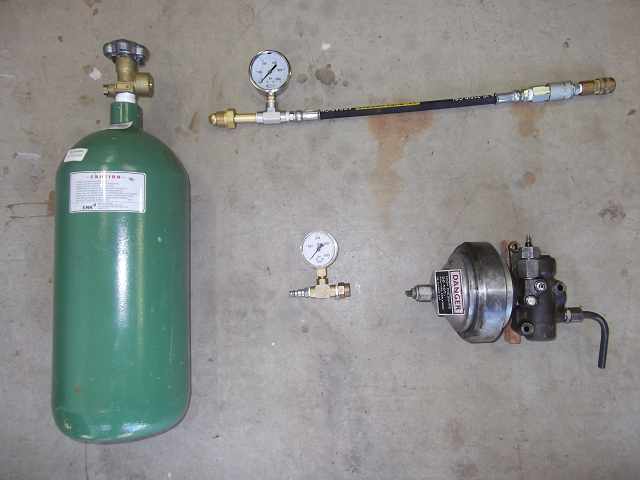 The tank is a "40 cubic foot" tank, so called because it holds 40 cubic feet at one atmosphere, which is charged to 2,000 PSI by the distributor and will yield 15 charges, by my calculations. A re-fill is around $25. Because it has Nitrogen, the valve on the tank has an adapter type called "CGA-580", and is inexpensive to buy. This is the fitting that would go on a regulator, but as you see I had no regulator, so I attached a gauge directly. I did have a gauge, and it is a more expensive gauge than necessary, but I didn't know that at the time I bought it. The Gauge will measure the pressure in the line at that point. I was careful to watch this gauge and I cracked the valve just the tiniest bit and I closed the valve when it reached 1,000. So, I was the regulator... 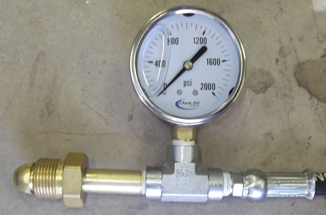 The hose came from an outfit here in Sacramento that supplied the other parts I didn't already have and they made it for me from a section of scrap they had lying around. The plumbing on the accumulator end of the line is whatever is necessary to attach to the female end of a standard shop compressor quick-release. I have more than is necessary because I changed my design as my understanding of the problem increased, so if yours looks different, that's probably a good thing. I could probably eliminate the larger steel quick-release adapter and attach the brass one directly to the hose, and when I go back to my shop this afternoon, I'll investigate that. Fewer parts is fewer problems... In fact, I could eliminate all the quick-release stuff period, but I used the gauge fitting with my compressor to charge the accumulator to 125 PSI and test my check valve, and I think that is a facility worth keeping. Why waste nitrogen on a leaky check valve? 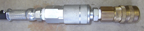 Finally, we get to the accumulator gauge. This is a pretty inexpensive gauge and is the wrong scale, in my opinion. It should be 0 - 2,000 PSI, since you will get twice the resolution over 0 - 4,000 PSI. I have no idea why I thought 0 - 4,000 PSI was the correct range for this. Notice that it is only the accumulator check valve away from the internal accumulator pressure, so I think it is a pretty good measure. Notice also that the check valve in the female line quick-release for the nitrogen distribution is upstream of of this assembly. Not pictured (mea culpa) is the detail of the brass fitting you see on the right-hand side of the tee, which actually attached to the accumulator check valve. It doesn't fit very tightly. I put an o-ring in it and I spun the gauge around hand tight, and more like finger-tip tight, and it did not leak and did charge the accumulator to 1,000 PSI, which is remarkable. 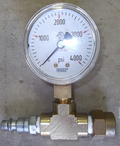 So, hook it up, carefully release nitrogen until the line pressure reads 1,000 PSI, and the close the valve. To disconnect, either disconnect the 580 at the valve with a wrench, spin the accumulator off the end (remember this was only finger-tip tight and very easy to do), or use the quick-release, which is actually the most difficult of the three. If you do use the quick-release, you must loosen the CGA-580 after anyway, because these quick-releases are not designed for 1,000 PSI and it is a check valve, so you're not strong enough to reattach without releasing the pressure in the hose. Well, at least I'm not... Hydraulic Bench Testing Now we get to the scary part... Ignore the setup for a moment. There are two interesting events during bench testing. 1) When the incoming fluid pressure equals the pressure of the nitrogen, and 2) when the incoming fluid pressure exceeds the ACV cut-out pressure. I manage to misunderstand both of these events... First, let's introduce the players: The hydraulic hand pump: 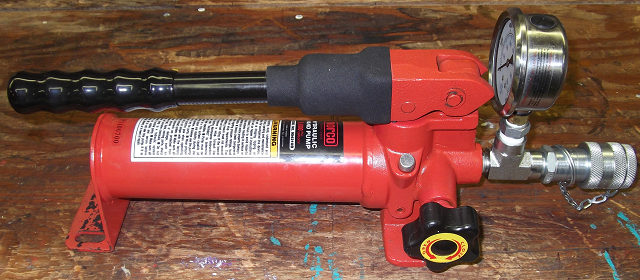 The Accumulator, in harness: 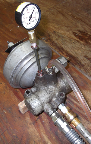 The fluid recovery station: 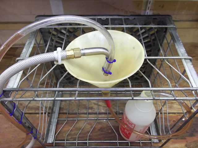 The pump came with instruction to not use brake fluid, but it has only one o-ring, which can be replaced in literally five minutes -- I know, I did it. I replaced the stock nitrile o-ring with a green HNBR o-ring, which efunda claims is "sometimes suitable" for brake fluid. That's good enough for me. So, after this, I did put home-brew RR363 in it. Notice, that I do not have a re-circulating system, like Jim, because my reservoir at the pump is pretty large compared to a bottle jack, and I accidentally made a funnel from a old carpenter's snap-line chalk re-fill container and a dip stick from a squirt cleaner draw tube which made refilling very easy. I only ever need to re-fill once per accumulator. This was initially a real messy part, until I put two nails in the edge of the bench which made re-filling trivial. Funnel: 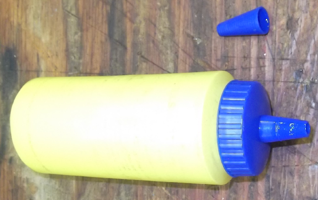 Dip Stick: Cover top with finger to measure, then release it back to the reservoir. 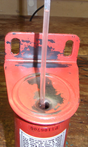 Refill Bracket: If a re-fill is necessary, then it need to be as convenient as possible. This worked incredibly well. Two nail! 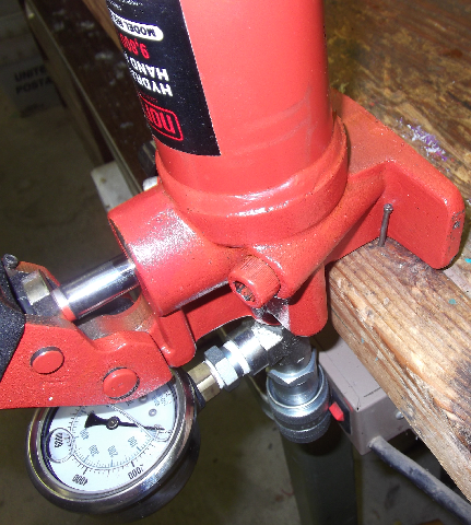 Putting it all together: The pump will hold two funnels-full. The funnel will not drain while seated, so accurate measurements are easy. Then with a full funnel, lift slightly, allowing air in the reservoir to escape... 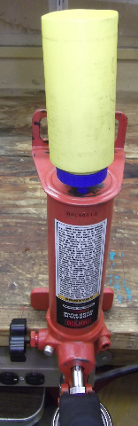 First things first. Test the pressure switch with an ohm meter -- one lead on the body and one on the single wire connection point. At zero pressure, you should see continuity, meaning zero-ish ohms. There is a lot of air in the system, so bleed it from the bleed valve. I used a clear tube so I could see the bubbles. Fluid returns to the recovery station cleverly disguised and a milk crate tipped on its side. You can guess how much is left in the pump by observing how much is in the recovery station. When the bubbles stop, snug the bleed nipple. Pump until pressure stops changing the first time. At this point, the meters will read the pressure of the nitrogen. The pressure switch should now show non-zero resistance, in fact it should register "open" meaning infinite-ish ohms. Recognize that with zero brake fluid, it takes a lot of brake fluid to proportionally change the volume of nitrogen enough to read a change in pressure. If you're not happy with this pressure reading, then release the fluid from the bleeder valve, and re-attach the nitrogen charging equipment. No need to disconnect all the hydraulics. My first accumulator was only charged to 700 PSI, so I had to investigate that. Turned out that I had a defective o-ring in my check valve, and I needed to open it up completely to fix that. As you develop your triceps, the resistance at the pump handle will increase and you will notice that the pressure increases as the nitrogen volume decreases. Eventually you will pass 2,000 PSI and at some point before 2,500 PSI the pump will suddenly exhibit zero resistance! At this point, if you keep pumping, you will notice fluid returning to the fluid recovery station. I let mine sit for a few days to be sure that they held pressure and that there were no leaks. One final note: There is a hydraulic equivalent of a quick release. It was pretty expensive, but I think it was WELL! worth it. 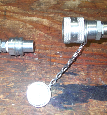 Hope you enjoyed reading this as much as I enjoyed writing it, Chris. | ||
Bob uk Unregistered guest Posted From: 94.197.122.78 |
The disks are RR only I do find it entertaining I add jokes and word play to jolly it up a bit I understand prefectly what you are doing You know that hydraulics systems work but you want to witness it yourself At the moment I have been looking at how to control electric motors I know about the theory but I want understand down to electron level I think to be a good engineer you need to be a bit nerdy sometimes I am using 12VDC for my experiments 2300 psi is like mains 240v dangerous Poeple have been killed by hydraulic system At a scrap yard near me the owner lost his leg because he repaired the crusher incorrectly using the wrong type valve In was advised by an engineer that he was playing with fire and ignored the advice Health and safety is important because people have have been killed because no one realise that that could happen Who would have thought that a gust of wind could knock a crane over If the valvebody had been fitted to the car then you could have relieved the pressure by pumping the brakes So write the funnies but don't take chances (Message approved by david_gore) | ||
Jan Forrest Grand Master Username: got_one Post Number: 559 Registered: 1-2008 |
"The tank is a "40 cubic foot" tank, so called because it holds 40 cubic feet at one atmosphere." I think you mean that it holds the equivalent of 40 cubic feet at one atmosphere by squishing it in at up to 2,000psi. My 12 litre, 232 BAR (3,400psi) SCUBA tank is larger than that one! | ||
Geoff Wootton Grand Master Username: dounraey Post Number: 421 Registered: 5-2012 |
Hi Chris Thanks for putting this information up. I am assuming the reason you use two gauges is to add to the versatility of your system. For anyone just interested in a straight nitrogen charge, then only one gauge is required. Is this correct? I have seen many adverts on ebay etc for paintball nitrogen bottles. I assume these do not come pre-charged. Did you buy your bottle locally or mail order? Also, where did you get it charged? In regard to safety, what I really like about the paintball method is it is failsafe. The nitrogen bottle has a 2000 psi charge so if you accidentally overcharge the accumulator (sticking CGA-580 for example) you can only ever put 2000 psi into the accumulator, which is pressure tested to 2300 psi every time you start the engine. Geoff | ||
Chris Miller Frequent User Username: cjm51213 Post Number: 95 Registered: 5-2013 |
Hi Geoff, > I am assuming the reason you use two gauges > is to add to the versatility of your system. There is no design requirement for the two gauges; they are not measuring different things; it just evolved that way. The downstream gauge was part of the paintball equipment and used the only fitting I had that fit the check valve of the accumulator, so that assembly already existed. The upstream gauge is there because at the time I was reconstituting my re-charge capability, I couldn't find my paintball equipment; I had reorganized my shop and I had reclassified the paintball stuff as “equipment” (tools) and no longer as “material” (supplies) supporting a project. As equipment, it goes with all the other compressed air tools, which was why I couldn't find it on the partial projects shelf when I went to find it. I needed to have one gauge, so I designed the hose to have a gauge where a regulator would normally be. Then I found the paintball equipment! So I was able to use that downstream assembly to bridge the hose to the accumulator and it already had the gauge. I did replace the quick-release from paintball size (brass male) to shop compressor size (steel male) so I could test the accumulator check valve with the shop compressor. 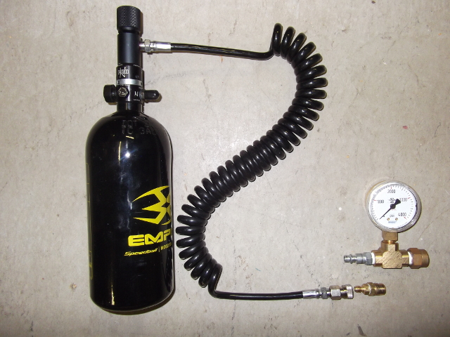 > For anyone just interested in a straight nitrogen > charge, then only one gauge is required. Is this correct? Yes. Designs with two gauges usually measure both the pressure available in the tank and the pressure being output at the moment. We're really only interested in the delivery pressure. But, let's investigate the premise of that question... If you think you need to only recharge the accumulator then you have to ask, “Why?”. The nitrogen can only escape two ways – through the check valve or through the diaphragm. If the diaphragm is leaking, you need to rebuild. If the check valve is leaking, then you won't be able to hold a charge long enough to cap it. The short observation is that if you think you need to recharge, then you need to rebuild. > I have seen many adverts on ebay etc for paintball nitrogen > bottles. I assume these do not come pre-charged. I agree. > Did you buy your bottle locally or mail order? Probably Amazon.com. I can't always remember what I had for breakfast, and it you have been following some of these exploits, then you know that I couldn't remember that I had reclassified the paintball equipment and filed it where it ought to go under that classification. I did this without remembering any of it, until I discovered the paintball equipment neatly filed with all the other compressed air tools... > Also, where did you get it charged? What you see in my setup is not paintball equipment; it is all industry standard stuff, and coincidentally, I never filled the paintball canister that I have. > In regard to safety, what I really like about the paintball > method is it is failsafe. The nitrogen bottle has a 2000 psi > charge so if you accidentally overcharge the accumulator > (sticking CGA-580 for example) you can only ever put 2000 > psi into the accumulator, which is pressure tested to 2300 > psi every time you start the engine. I think I have confused paintball and “industry standard”... My tank is an “industry standard” “40 foot” tank and was filled to a traditional 2,000 PSI. Paintball canisters are "48 cubic inches", which is a lot smaller, and filled to 3,000 PSI or 4,500 PSI. I have no regulator, because I don't need sustained pressure(CGA-580 describes the valve on the tank, which dictates the connector to attach to it.); the paintball canisters have regulators built in to their valves, so even though they are typically much higher pressure, they can only source 800 PSI normally or 1,100 PSI with a special regulator. A paintball canister costs about $45 and comes with an 800 PSI regulator, which is perfectly fine. It will undercharge your accumulators, but that will reduce their duration and not their performance, meaning if you are driving on the accumulators alone because the engine has stalled, they will work just fine for some number of cycles, but you will exhaust your pressure before you exhaust the fluid. It is possible the 800 PSI is perfectly adequate to perform the necessary functions, meaning there will be no detrimental effects of this undercharge. However, the manual says 1,000 PSI, and I suspect there is a reason for that. And if you're going to take all the trouble to rebuild them, you might as well charge them to spec. The special high pressure regulator costs $60 and the a fill is about $25, so your cost will be $130. I paid $130 for my tank and it was already filled. Re-fills are about the same cost as the tiny paintball canister, believe it or not. The paintball system is really a clever solution and pretty cheap if you are happy with 800 PSI and I don't see any reason why you shouldn't be, and you don't have to fill many accumulators. The trick is re-filling the canister. The paintball shops don't deal in nitrogen any more; they all use compressed air. The traditional bottled gas places can't handle them and my local branch said that they could “Send it out and see what they can do.” which was less than inspiring. So, since I never actually did that, I have no experience re-filling the paintball canisters. It turned out that the industry standard approach was no more expensive than the paintball approach, if you deem 1,000 PSI an important goal. If it costs $25 per fill on the paintball canister and you only get two or three accumulator charges from it, the industry standard approach becomes much cheaper pretty quickly. | ||
Jan Forrest Grand Master Username: got_one Post Number: 560 Registered: 1-2008 |
Although carriage terms/rules/laws may be different in different countries, at least in the UK you may not send filled pressurised containers through the British Post Office/Royal Mail/Parcel Force. Most private couriers may handle them, but they are supposed to have the correct safety equipment for the job. |